KTI KGC-261-DP-BT/G User manual

-1-
KGC-261-DP-BT/G
KGC-261-DP-BT/I
Industrial Managed
10/100/1000Base-T to Dual-speed Fiber
Media Converters
with IEEE 802.3bt PSE Support
Installation Guide
DOC. 201113
All manuals and user guides at all-guides.com

-2-
(C) 2020 KTI Networks Inc. All rights reserved. No part of this documentation may be reproduced in any form
or by any means or used to make any directive work (such as translation or transformation) without permission
from KTI Networks Inc.
KTI Networks Inc. reserves the right to revise this documentation and to make changes in content from time to
time without obligation on the part of KTI Networks Inc. to provide notification of such revision or change.
For more information, contact:
United States KTI Networks Inc.
P.O. BOX 631008
Houston, Texas 77263-1008
Phone: 713-2663891
Fax: 713-2663893
E-mail: kti@ktinet.com
URL: http://www.ktinet.com/
International Fax: 886-2-26983873
E-mail: kti@ktinet.com.tw
URL: http://www.ktinet.com.tw/
All manuals and user guides at all-guides.com

-3-
The information contained in this document is subject to change without prior notice. Copyright (C) All Rights
Reserved.
TRADEMARKS
Ethernet is a registered trademark of Xerox Corp.
FCC NOTICE
This device complies with Part 15 of the FCC Rules. Operation is subject to the following two conditions: (1)
This device may not cause harmful interference, and (2) This device must accept any interference received,
including the interference that may cause undesired operation.
FCC CFR Title 47 Part 15 Subpart B Class A
CISPR 22
ANSI C63.4
ICES-003 Issue 6 Class A
CE NOTICE
Marking by the symbol indicates compliance of this equipment to the EMC directive 2014/30/EU of the
European Community. Such marking is indicative that this equipment meets or exceeds the following technical
standards:
EMC
EN 61000-6-4 Class A
EN 61000-6-2
IEC 61000-4-2
IEC 61000-4-3
IEC 61000-4-4
IEC 61000-4-5
IEC 61000-4-6
IEC 61000-4-8
VCCI-A Notice
All manuals and user guides at all-guides.com

-4-
Table of Contents
1. Introduction...................................................................................................................................6
1.1 Model Definitions.................................................................................................7
1.2 Features..............................................................................................................8
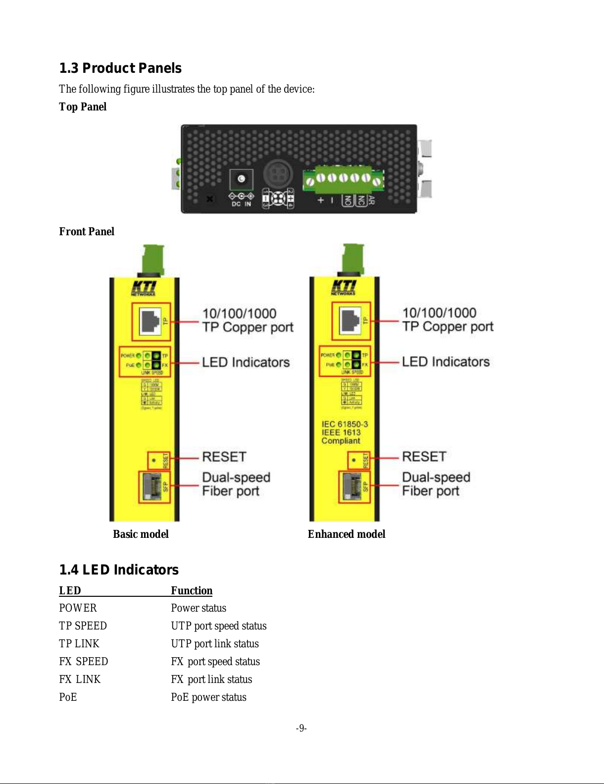
1.3 Product Panels....................................................................................................9
1.4 LED Indicators.....................................................................................................9
1.5 Specifications....................................................................................................10
1.6 IEC 61850-3 & IEEE 1613.................................................................................14
2. Installation...................................................................................................................................16
2.1 Unpacking.........................................................................................................16
2.2 Safety Cautions.................................................................................................16
2.3 Mounting the Device to a DIN-Rail ....................................................................17
2.4 Mounting the Device on a Panel........................................................................19
2.5 Applying Power................................................................................................. 21
2.5.1 DC power Terminal Block...............................................................................21
2.5.2 DC Power DIN................................................................................................22
2.5.3 DC Power Jack ..............................................................................................22
2.6 Alarm Relay Output........................................................................................... 23
2.7 Reset Button .....................................................................................................24
3. Making LAN Connections..........................................................................................................25
3.1 10/100/1000 TP Copper Port.............................................................................25
3.2 Making Fiber Connection...................................................................................26
3.3 Making PoE Connection....................................................................................27
3.4 LED Indication...................................................................................................30
4. Functions ....................................................................................................................................31
4.1 Converter Function............................................................................................31
4.2 Link Fault Pass Through Function.....................................................................31
4.3 802.1Q Control Function ...................................................................................32
4.3.1 VLAN Operation.............................................................................................34
4.4 SNMP Trap Function.........................................................................................36
All manuals and user guides at all-guides.com

-5-
5. Web Management.......................................................................................................................37
5.1 Start Browser Software and Making Connection ...............................................37
5.2 Login to the Device Unit .................................................................................... 37
5.3 Main Management Menu...................................................................................38
5.4 Configuration.....................................................................................................40
5.4.1 System...........................................................................................................40
5.4.1.1 Management VLAN.....................................................................................43
5.4.2 Ports...............................................................................................................44
5.4.2.1 802.1Q Filtering...........................................................................................48
5.4.3 LLDP.............................................................................................................. 50
5.4.4 OPA ...............................................................................................................52
5.4.5 ALS................................................................................................................ 52
5.5 Monitoring.........................................................................................................53
5.5.1 Statistics Overview.........................................................................................53
5.5.2 LLDP Statistics............................................................................................... 55
5.5.3 LLDP Table....................................................................................................56
5.5.4 SFP DDM.......................................................................................................57
5.5.5 PoE................................................................................................................ 58
5.5.6 Ping................................................................................................................ 59
5.6 Maintenance......................................................................................................60
5.6.1 Reboot System...............................................................................................60
5.6.2 Restore Default ..............................................................................................60
5.6.3 Update Firmware............................................................................................60
5.6.4 Configuration File Transfer.............................................................................61
5.6.5 Logout............................................................................................................61
6. SNMP Support ............................................................................................................................62
Appendix A. Factory Default Settings..........................................................................................63
Appendix B. Models & Optical Specifications.............................................................................66
All manuals and user guides at all-guides.com

-6-
1. Introduction
The product series are Gigabit Ethernet media converters which provide the following features:
Data Conversion between different Media types and Speed
The media converter supports the following conversions:
1000Mbps (1000BASE-T) copper to/from 1000Mbps (1000BASE-X) fiber
100Mbps (100BASE-TX) copper to/from 1000Mbps (1000BASE-X) fiber
10Mbps (10BASE-T) copper to/from 1000Mbps (1000BASE-X) fiber
1000Mbps (1000BASE-T) copper to/from 100Mbps (100BASE-FX) fiber
100Mbps (100BASE-TX) copper to/from 100Mbps (100BASE-FX) fiber
10Mbps (10BASE-T) copper to/from 100Mbps (100BASE-FX) fiber
Dual-speed SFP Fiber Connectivity
The SFP port can be installed with different optional SFP optical fiber transceiver to support multimode or
single mode fiber for short reach up to long reach distance. The SFP can support both 1000BASE-X and
100BASE-FX fiber connection. This feature extends a wider application range with this device.
Link Fault Pass-Through
This important feature of a media converter can force the link to shut down as soon as it notices that the other
link has failed. It allows a link partner on one cable segment can notice a link fault occurred on the other
segment and give application a chance to react.
All manuals and user guides at all-guides.com

-7-
802.1Q Control
With software configuration support, the device is enhanced with more 802.1Q control features for VLAN
applications rather than just a typical media converter function. The optional features include:
Filtering all untagged packets
Filtering all tagged packets
Filtering tagged packets with certain VID
Egress un-tagging
Egress tagging
Double tagging
802.1ad Q-in-Q support
Optical Power Alarm (OPA)
OPA function allows to set lower and upper alarm thresholds for the optical power of the fiber port. The alarm
is sent via relay alarm output and SNMP trap.
Auto Laser Shutdown (ALS)
ALS function is supported for the fiber port and used to automatically shut down the output power of the
transmitter in case of fiber break for human safety purpose or hazardous environment.
Web Management
The device is embedded with an Http server which provides management functions for advanced network
functions including Port Control and 802.1Q and 802.1ad functions. The management can be performed via
Web browser based interface over TCP/IP network.
IEEE 802.3bt PSE
The device is equipped with PoE PSE capability that can deliver output power supporting IEEE 802.3bt
compliant 90W Type 4 PDs, IEEE 802.3at Type 2 high-power PDs, and IEEE 802.3af Type 1 PDs. The device
supports both Fast Ethernet connection and Gigabit Ethernet connection.
1.1 Model Definitions
Model
Description
IEC 61850-3 & IEEE 1613
Compliance verified
KGC-261-DP-BT/G
(Basic model)
Industrial Managed 10/100/1000Base-T to Dual-speed Fiber
Media Converter with IEEE 802.3bt PSE Support
N/A
KGC-261-DP-BT/I
(Enhanced model)
IEC 61850-3 Managed 10/100/1000Base-T to Dual-speed
Fiber Media Converter with IEEE 802.3bt PSE Support
Yes
All manuals and user guides at all-guides.com

-8-
1.2 Features
Tri-speed 10Mbps/100Mbps/1Gbps copper to dual-speed 100Mbps/1Gbps fiber conversion
Comply with IEEE 802.3, 802.3u, 802.3ab, 802.3z, 802.3af, 802.3at, 802.3bt standard
Support full wire speed conversion for Gigabit copper to Gigabit fiber
Support auto-negotiation with link partners
Provide dual-speed SFP on fiber port for mounting variety of fiber options
Provide important LFPT (Link Fault Pass Through) media converter function
Support Jumbo frame conversion
Energy efficient Ethernet (EEE) support
Alarm events relay output
Fiber support for multimode, short reach up to long reach single mode fiber, Bi-Di applications
Web-based configuration management support
Support SNMP management
Optical Power Alarm (OPA) function if optical power is higher than a upper limit setting or lower than a
lower limit setting
Auto Laser Shutdown (ALS) function in case of fiber cable break
Multiple built-in power connectors to support a variety of external power supply
Power over Ethernet (IEEE 802.3bt PoE) PSE
Supports both Fast Ethernet and Gigabit Ethernet
Backward compatible with IEEE 802.3af and IEEE 802.3at-compliant PDs
Type 1 ~ Type 4 compliant PD discovery & classification
Delivers power output to support Type 3 and Type 4 PD over both 2-pair lines
Power shutdown protection for incompliant PD
Power shutdown protection for disconnection
Power shutdown protection for overload, over-current, and short circuit
All manuals and user guides at all-guides.com

-9-
1.3 Product Panels
The following figure illustrates the top panel of the device:
Top Panel
Front Panel
Basic model Enhanced model
1.4 LED Indicators
LED Function
POWER Power status
TP SPEED UTP port speed status
TP LINK UTP port link status
FX SPEED FX port speed status
FX LINK FX port link status
PoE PoE power status
All manuals and user guides at all-guides.com

-10-
1.5 Specifications
10/100/1000 Twisted-pair Copper Port (UTP, RJ-45)
Compliance IEEE 802.3 10Base-T, IEEE 802.3u 100Base-TX,
IEEE 802.3u 1000Base-T
Connectors Shielded RJ-45 jacks
Pin assignments Auto MDI/MDI-X detection
Configuration Auto-negotiation, manual settings or software control
Transmission rate 10Mbps, 100Mbps, 1000Mbps
Duplex support Full/Half duplex
Network cable Cat.5 UTP or better
PoE IEEE 802.3af, IEEE 802.3at, IEEE 802.3bt PSE
Pin assignments Vpoe: PoE power
Pin
10/100Base-TX
1000Base-T
PoE
1
RX+
BI_DA+
Vpoe+
2
RX-
BI_DA-
Vpoe+
3
TX+
BI_DB+
Vpoe-
4
BI_DC+
Vpoe+
5
BI_DC-
Vpoe+
6
TX-
BI_DB-
Vpoe-
7
BI_DD+
Vpoe-
8
BI_DD-
Vpoe-
Dual-speed Fiber Port (FX, SFP)
Compliance IEEE 802.3 1000Base-X, 100BASE-FX
Connectors SFP for optional SFP type fiber transceivers
Configuration Auto, 1000Mbps Full duplex Auto-negotiation, 100Mbps Full
Transmission rate 1000Mbps, 100Mbps (Dual-speed support)
Network cables MMF 50/125 60/125, SMF 9/125
Eye safety IEC 825 compliant
Basic Functions
MAC addresses Support up to 8K
Forwarding technology Store and forward
Maximum packet length Jumbo frame support up to 9600 bytes
Flow control IEEE 802.3x pause frame base for full duplex operation
Back pressure for half duplex operation
All manuals and user guides at all-guides.com

-11-
DC Terminal Block Input
Connector Flange terminal block 5P
Contacts Rating 15A 57VDC
Pin
Marking
Remark
1
DC+
DC power input (+)
2
DC-
DC power input (-)
3,4,5
AR
Alarm relay output contacts
Alarm Relay Output
Contacts 3 dry contacts for NC & NO pairs
Rating 30VDC/1A or 120VAC/0.5A
Alarm events Power failure, configured port link fault, OPA alarm
Pin
Marking
Alarm Relay Output contacts
3,4
AR/NO
NO pair: Normal –open, Alarm - shorted
4,5
AR/NC
NC pair: Normal –shorted, Alarm - open
DC Power Jack
Connector DC Jack (-Ø6.3mm/+Ø2.0mm) for external AC-DC power adapter
Contacts Rating 8A 48V
Contact
Marking
Remark
Center (Ø2.0mm)
<+>
DC power input (+)
Outer (Ø6.3mm)
<->
DC power input (-)
DC Power DIN
Connector Female power Mini-DIN-4 for external AC-DC power adapter
Contacts Rating 7.5A 48V
Pins
Marking
Remark
2, 4
DC+
DC power input (+)
1, 3
DC-
DC power input (-)
DC Power Input
DC working voltages +12 ~ +57V for general applications
+45 ~ +57V for PoE applications
Power consumption 4W(PoE inactive), 5W (PoE active, excluded PoE load)
Protection Polarity Reversal shutdown
All manuals and user guides at all-guides.com

-12-
Isolation DC+/- vs. Frame Ground 1.5KV
RESET
Push Button Short push - System reset
Long push –Restore factory default settings
Power Over Ethernet (PoE)
PoE type PSE
Standard IEEE 802.3af, IEEE 802.3at, and IEEE 802.3bt
PSE power pins Pin 1/2/4/5: Vpoe+, Pin 3/6/7/8: Vpoe- (Vpoe comes from DC power input)
Power delivery 95W max. at port output (Depending on DC power voltage)
Protection PoE output shutdown
Protection events Incompliant PD detection, PD disconnection
Overload, Over-current, Short-circuit, Under voltage
PD classes support PSE output vs. PD input
Compliant
PD classes
IEEE std.
DC power
min. *1
PSE output
power max. *2
Cable
power pairs
PD Available
power min. *3
802.3af
802.3at
802.3bt
Class 1
45V
5.3W
2
3.84W
Class 2
45V
8.5W
2
6.49W
Class 3
45V
19W
2
13W
Class 4
45V
36W
4
25.5W
Class 5
51V
51W
4
40W
Class 6
51V
68W
4
51W
Class 7
53V
83W
4
62W
Class 8
53V
95W
4
71.3W
*1: The minimum DC power voltage to support the specified PSE output
*2: The maximum output power at the PSE end for the requested PD class
*3: The minimum power received at the PD end with maximum output at the PSE end in worst case
Mechanical
Dimension (base) 40 x 106 x 140 mm (WxDxH)
Housing Enclosed metal with no fan
Mounting Din-rail mounting
Panel mounting (with optional bracket)
MTBF
Basic model 260K hours
All manuals and user guides at all-guides.com

-13-
Enhanced model 260K hours
Environmental
Operating Temperature Typical -40oC ~ +75oC
Storage Temperature -40oC ~ +85oC
Relative Humidity 5% ~ 95% non-condensing
Tests and Approvals
FCC CFR Title 47 Part 15 Subpart B Class A
CISPR 22
ANSI C63.4
ICES-003 Issue 6 Class A
CE EMC Class A
VCCI Class A
EN 61000-6-4 Emission
EN 61000-6-2 Immunity
IEC 61850-3 EMC & environment for power substation
IEEE 1613 for power substation
LVD, IEC62368-1 Safety
IEC 60068-2-64 Vibration
IEC 60068-2-27 30G Shock test
Management:
Management Web-based browser interface, SNMP manager
Port Control Operating mode, Flow control, LLDP
Packet Filtering 802.1Q tagged packet filtering, Untagged packet filtering
802.1Q VLAN Ingress 802.1Q tag stripping, Egress 802.1Q tagging (tag insertion)
S-tag tagging (802.1ad double tagging)
OPA Control Configuration
ALS Control Configuration
PoE Power over Ethernet control
Maintenance Restore factory default, reboot, firmware update, configuration file save & upload
SNMP Private MIB DDM status, OPA control, ALS control, PoE status
SNMP Trap Trap events: Boot up, Port link change, OPA trap
Power saving Disable, Link Up, Link Down, Full
All manuals and user guides at all-guides.com

-14-
1.6 IEC 61850-3 & IEEE 1613
The enhanced model has been verified that it is compliant with IEC 61850-3 EMC, environmental and
mechanical requirements and IEEE 1613 requirements for power substations.
IEC 61850-3
IEC 61850-3 defines the general requirements, mainly regarding construction, design and environmental
conditions for utility communication and automation IEDs (intelligent electronic devices) and systems in
power plant and substation environments.
IEEE 1613
IEEE Standard Environmental and Testing Requirements for Communications Networking Devices in Electric
Power Substations
The enhanced model: IEC 61850-3 EMC Test Specifications
IEC 61850-3
Test
Level
C 6.7.4 / EN 55022
DC IN conducted emission
Class A
C 6.7.4 / EN 55022
LAN conducted emission
Class A
C 6.7.4 / EN 55022
Radiated emission
Class A
C 6.7.3 / IEC 61000-4-2
ESD
+/-8kV Air, +/-6kV Contact
C 6.7.3 / IEC 61000-4-3
RFS
10V/m
C 6.7.3 / IEC 61000-4-4
EFB
DC IN & LAN: +/-4kV
C 6.7.3 / IEC 61000-4-5
Surge
DC IN +/-1kV, LAN +/-4kV
C 6.7.3 / IEC 61000-4-6
CD
DC IN & LAN: 10V
C 6.7.3 / IEC 61000-4-8
PFM
100A/m, 1000A/m
C 6.7.3 / IEC 61000-4-11
AC power Dip
N/A: No AC input in DUT
C 6.7.3 / IEC 61000-4-16
MFV
DC IN & LAN: 30V/300V
C 6.7.3 / IEC 61000-4-17
DC ripple
10% of DC IN
C 6.7.3 / IEC 61000-4-18
Damped Oscillatory Wave
DC IN & LAN: +/-2.5kV
C 6.7.3 / IEC 61000-4-29
DC dips and interruption
DC IN 40% 0.1s, 0% 50ms
The enhanced model: IEC 61850-3 Environmental Test Specifications
IEC 61850-3
Test
Specification
C 6.9.3
Dry heat - operational
+75℃, 30%RH, 72hrs
C 6.9.3
Cold –operational
-40℃, 72hrs
C 6.9.3
Change of temperature - operational
-40 ~ 75℃, 3hr, 6 cycles
C 6.9.3
Damp heat - operational
+75℃, 95%RH, 72hrs
All manuals and user guides at all-guides.com

-15-
C 6.9.3
Damp heat –steady state
+40℃, 95%RH, 48hrs
C 6.9.3
Humidity
+25℃95%RH 12hrs/
55oC 95%RH 12hrs, 2 cycles
C 6.9.3
Dry heat - storage
+85℃, 30%RH, 96hrs
C 6.9.3
Cold –storage
-40℃, 96hrs
The enhanced model: IEC 61850-3 Mechanical Test Specifications
IEC 61850-3
Test
Specification
C 6.10
Vibration –resonant search
Class 2, 1Gn, 1/axis
C 6.10
Vibration –endurance
Class 2, 2Gn, 20/axis
C 6.10
Shock - responds
Class 2, 10Gn, 11ms, 3/axis
C 6.10
Shock - withstand
Class 2, 30Gn, 11ms, 3/axis
C 6.10
Shock –bump
Class 2, 20Gn, 16ms, 1000/axis
C 6.10
Seismic
Class 2, x –2Gn, y –1Gn, 10min.
C 6.10
Enclosure protection
Ingress of solid foreign subjects >=2.5mm
The enhanced model: IEEE 1613 Test Specifications
IEEE 1613
Test
Level
Clause 4.1
DC rated control power inputs
80% 100% Max. DC IN
Clause 4.2
Ripple on DC power input
10%
Clause 4.3
AC rated control power inputs
N/A: No AC input in DUT
Clause 5.2
Dielectric strength
DC IN vs. LAN ports: 2.8kV
Clause 5.3
Impulse voltage
DC IN vs. LAN ports: 1000Vac
Clause 6 / EMC
1Mhz oscillatory wave
DC IN & LAN: +/-2.5kV
Clause 6 / EMC
EFB
DC IN & LAN: +/-4kV
Clause 7 / EMC
RFS
10V/m
Clause 8 / EMC
ESD
+/-8kV Air, +/-6kV Contact
All manuals and user guides at all-guides.com

-16-
2. Installation
2.1 Unpacking
The product package contains:
The device unit for Din-rail mounting
QR code label linking to product documentation folder
2.2 Safety Cautions
To reduce the risk of bodily injury, electrical shock, fire and damage to the product, observe the following
precautions.
Do not service any product except as explained in your system documentation.
Opening or removing covers may expose you to electrical shock.
Only a trained service technician should service components inside these compartments.
If any of the following conditions occur, unplug the product from the electrical outlet and replace the
part or contact your trained service provider:
-The power cable, extension cable, or plug is damaged.
-An object has fallen into the product.
-The product has been exposed to water.
-The product has been dropped or damaged.
-The product does not operate correctly when you follow the operating instructions.
Do not push any objects into the openings of your system. Doing so can cause fire or electric shock by
shorting out interior components.
Operate the product only from the type of external power source indicated on the electrical ratings
label. If you are not sure of the type of power source required, consult your service provider or local
power company.
Since the surface temperature of the device may be higher than 70℃in range of
the rated operating temperatures, install and operate the product only by authorized
personnel only. Install the product at a restricted area where un-authorized persons
cannot reach.
All manuals and user guides at all-guides.com

-17-
2.3 Mounting the Device to a DIN-Rail
In the product package, a DIN-rail bracket is provided or has been installed for mounting the device in a
industrial DIN-rail enclosure.
The steps to mount the device onto a DIN rail are:
1. Install the mounting bracket onto the back of the device with screws as shown below:
2. Attach bracket to the lower edge of the DIN rail and push the unit upward a little bit until the bracket can
clamp on the upper edge of the DIN rail.
3. Clamp the device to the DIN rail and make sure it is mounted securely.
All manuals and user guides at all-guides.com

-18-
Both models are with same dimension. The final dimension after DIN-rail bracket is installed is:
All manuals and user guides at all-guides.com

-19-
2.4 Mounting the Device on a Panel
The device may be provided optionally with a panel mounting bracket. The bracket supports mounting the
device on a plane surface securely. The mounting steps are:
1. Install the mounting bracket on the device.
2. Screw the bracket on the device.
3. Screw the device on a panel and the locations for screws are shown below:
All manuals and user guides at all-guides.com

-20-
Both models are with same dimension. The final dimension after the bracket is installed is:
All manuals and user guides at all-guides.com
This manual suits for next models
1
Table of contents
Other KTI Media Converter manuals