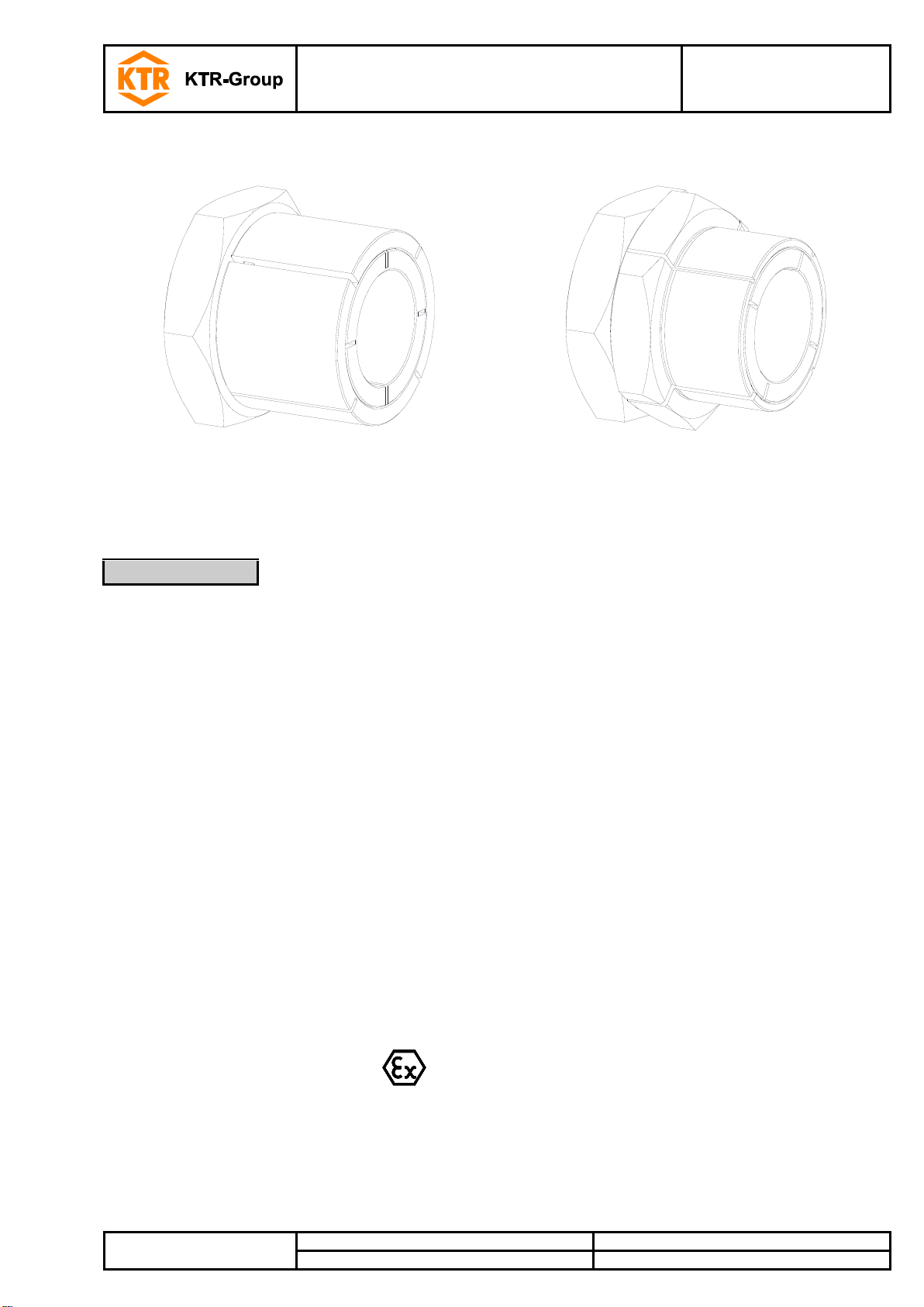
CLAMPEX®KTR 130 / KTR 131
Operating/Assembly instructions
Please observe protection
note ISO 16016.
Please read through these operating/assembly instructions carefully before you mount the clamping set.
Please pay special attention to the safety instructions!
The operating/assembly instructions are part of your product. Please store them carefully and close to the clamp-
ing set. The copyright for these operating/assembly instructions remains with KTR.
Warning of potentially explosive
atmospheres
This symbol indicates notes which may contribute to pre-
venting bodily injuries or serious bodily injuries that may
result in death caused by explosion.
Warning of personal injury
This symbol indicates notes which may contribute to pre-
venting bodily injuries or serious bodily injuries that may
result in death.
Warning of product damages
This symbol indicates notes which may contribute to pre-
venting material or machine damage.
This symbol indicates notes which may contribute to pre-
venting adverse results or conditions.
With assembly and disassembly of the clamping set it has to be made sure that the entire
drive train is secured against accidental switch-on. You may be seriously hurt by rotating
parts. Please make absolutely sure to read through and observe the following safety indica-
tions.
All operations on and with the clamping set have to be performed taking into account "safety first".
Please make sure to switch off the power pack before you perform your work on the clamping set.
Secure the power pack against accidental switch-on, e. g. by providing warning signs at the place of switch-on
or removing the fuse for current supply.
Do not reach into the operation area of the machine as long as it is in operation.
Please secure the rotating drive components against accidental contact. Please provide for the necessary
protection devices and covers.
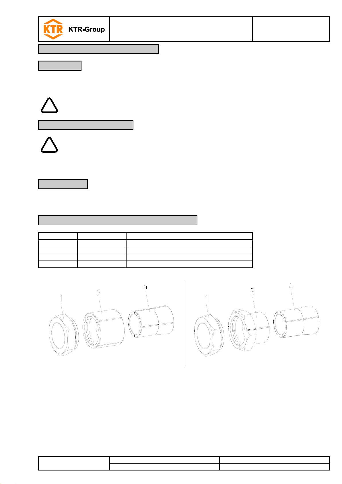
You may only assemble and disassemble the clamping set if you
have carefully read through the operating/assembly instructions and understood them
had technical training
are authorized by your company
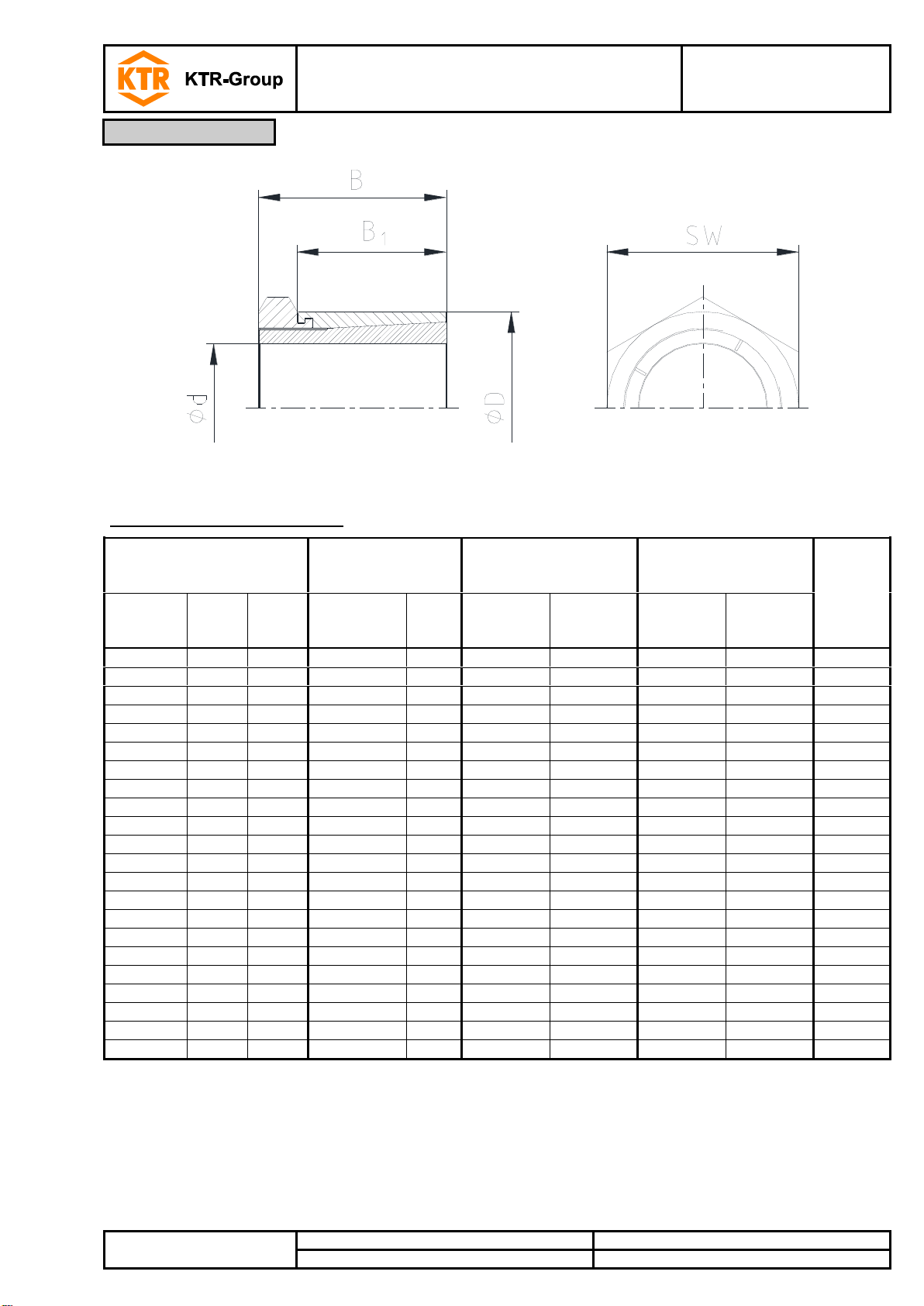
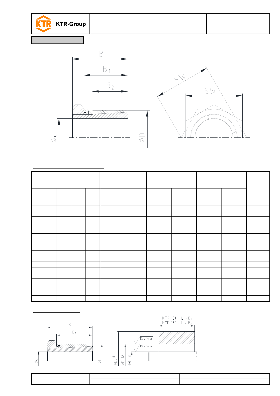
The clamping set may only be used in accordance with the technical data (see table 1 and 2). Unauthorized modi-
fications on the clamping set are not admissible. We will not assume liability for any damage that may arise. In the
interest of further development we reserve the right for technical modifications.
The clamping set described in here corresponds to the technical status at the time of printing of these operat-
ing/assembly instructions.
2.2 Safety and advice symbols
2.3 General hazard warnings