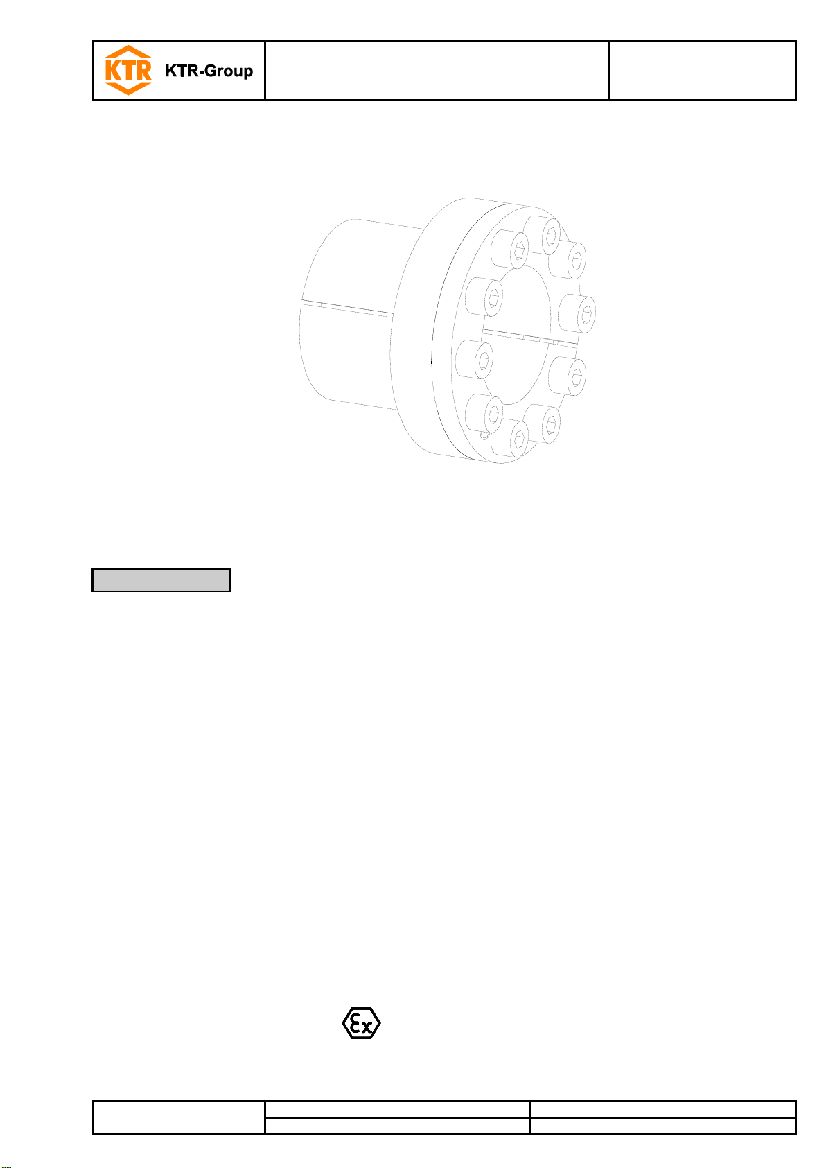
KTR-Group CLAMPEX KTR 250 Manual

CLAMPEX®KTR 250
Operating/Assembly instructions
KTR-N
Sheet:
Edition:
40817 EN
1 of 7
6
Please observe protection
note ISO 16016.
Drawn:
2016-09-09 Shg/Jh
Replacing:
KTR-N dated 2011-05-23
Verified:
2016-09-09 Shg
Replaced by:
CLAMPEX®KTR 250
The CLAMPEX®clamping set is a frictionally engaged, detachable shaft-hub-connection for cylindrical
shafts and bores without feather key.
1Technical data 2
2Advice 3
2.1 General advice 3
2.2 Safety and advice symbols 3
2.3 General hazard warnings 3
2.4 Intended use 4
3Storage, transport and packaging 4
3.1 Storage 4
3.2 Transport and packaging 4
4Assembly 5
4.1 Components of clamping set CLAMPEX®KTR 250 5
4.2 Assembly of the clamping set 5
4.3 Disassembly of clamping set 6
5Disposal 7
6Spares inventory, customer service addresses 7
7Advice regarding the use in hazardous locations according to
EU directive 2014/34/EU 7
Table of contents

CLAMPEX®KTR 250
Operating/Assembly instructions
KTR-N
Sheet:
Edition:
40817 EN
2 of 7
6
Please observe protection
note ISO 16016.
Drawn:
2016-09-09 Shg/Jh
Replacing:
KTR-N dated 2011-05-23
Verified:
2016-09-09 Shg
Replaced by:
1) Dimension DN: For
calculation of hub see
catalogue "Drive
Technology".
2) These are the
maximum screw
tightening torques.
They can be reduced
by a maximum of 40 %
of the figures
specified, with T, Fax,
PWand PNdeclining
proportionally.
Illustration 1: CLAMPEX®KTR 250
Table 1:
Dimensions
[mm]
Clamping screws
DIN EN ISO 4762 - 12.9
μtotal = 0.14
Transmittable
torque or axial force
Surface pressure
between clamping set
[N/mm2]
Weight
[kg]
d x D
B
B1
B2
B3
D1
M
Length
z
Quantity
TA2)
[Nm]
T
[Nm]
Fax
[kN]
Shaft
PW
Hub
PN
6 x 14
24.5
21.5
18.5
10.0
25
M3
10
4
2.6
11
4
162
69
0.05
8 x 15
29
25
21.5
11.5
27
M4
10
3
5.6
26
7
187
100
0.05
9 x 16
30
26
22.5
14.0
28
M4
10
4
5.6
37
8
173
97
0.06
10 x 16
30
26
22.5
14.0
29
M4
10
4
5.6
42
8
159
99
0.16
11 x 18
30
26
22.5
13.5
32
M4
10
4
5.6
50
9
162
99
0.18
12 x 18
30
26
22.5
13.5
32
M4
10
4
5.6
55
9
150
100
0.18
14 x 23
30
26
22.5
14
38
M4
10
6
5.6
100
14
193
118
0.20
15 x 24
42
36
28.5
16
44
M6
18
4
15
145
19
214
134
0.2
16 x 24
42
36
28.5
16
44
M6
18
4
15
155
19
201
134
0.30
17 x 25
42
36
28.5
16
45
M6
18
4
15
162
19
186
126
0.2
17 x 26
44
38
31
18
47
M6
18
4
17
180
21
184
120
0.2
18 x 26
44
38
31
18
47
M6
18
4
17
200
22
182
126
0.2
19 x 27
44
38
31
18
48
M6
18
4
17
210
22
171
121
0.3
20 x 28
44
38
31
18
49
M6
18
4
17
220
22
162
116
0.2
22 x 32
51
45
38
25
54
M6
18
4
17
250
23
110
75
0.3
24 x 34
51
45
38
25
56
M6
18
4
17
270
23
99
70
0.3
25 x 34
51
45
38
25
56
M6
18
4
17
280
22
95
70
0.3
28 x 39
51
45
38
25
61
M6
18
6
17
480
34
130
93
0.4
30 x 41
51
45
38
25
62
M6
18
6
17
510
34
120
88
0.4
32 x 43
51
45
38
25
65
M6
18
8
17
730
46
151
113
0.50
35 x 47
56
50
43
30
69
M6
18
8
17
800
46
115
86
0.5
38 x 50
56
50
43
30
72
M6
18
8
17
860
45
105
80
0.6
40 x 53
56
50
43
30
75
M6
18
8
17
900
45
99
75
0.6
42 x 55
65
57
49
32
78
M8
22
8
41
1800
86
169
129
0.9
45 x 59
73
65
57
40
85
M8
22
8
41
1900
84
124
95
1.0
48 x 62
78
70
62
45
87
M8
22
8
41
2000
83
102
79
1.0
50 x 65
78
70
62
45
92
M8
22
10
41
2600
104
123
94
1.3
55 x 71
83
75
67
50
98
M8
22
10
41
2900
105
102
79
1.5
60 x 77
83
75
67
50
104
M8
22
10
41
3100
103
91
71
1.7
65 x 84
83
75
67
50
111
M8
22
10
41
3400
105
85
66
1.9
70 x 90
101
91
80
60
119
M10
25
10
83
5800
166
105
81
2.9
75 x 95
101
91
80
60
126
M10
25
10
83
6200
165
97
77
2.3
80 x 100
106
96
85
65
131
M10
25
12
83
8000
200
102
82
3.3
85 x 106
106
96
85
65
137
M10
25
12
83
8500
200
96
77
3.6
90 x 112
106
96
85
65
143
M10
25
15
83
11200
249
113
91
3.9
95 x 120
106
96
85
65
153
M10
25
15
83
11800
248
107
84
4.5
100 x 125
114
102
89
65
162
M12
30
12
145
14600
292
119
95
5.5
110 x 140
140
128
114
90
180
M12
30
12
145
16000
291
78
61
8.0
120 x 155
140
128
114
90
198
M12
30
12
145
17400
290
71
55
10.5
130 x 165
140
128
114
90
208
M12
30
16
145
25000
385
87
69
11.9
1 Technical data

CLAMPEX®KTR 250
Operating/Assembly instructions
KTR-N
Sheet:
Edition:
40817 EN
3 of 7
6
Please observe protection
note ISO 16016.
Drawn:
2016-09-09 Shg/Jh
Replacing:
KTR-N dated 2011-05-23
Verified:
2016-09-09 Shg
Replaced by:
Tolerances, surfaces
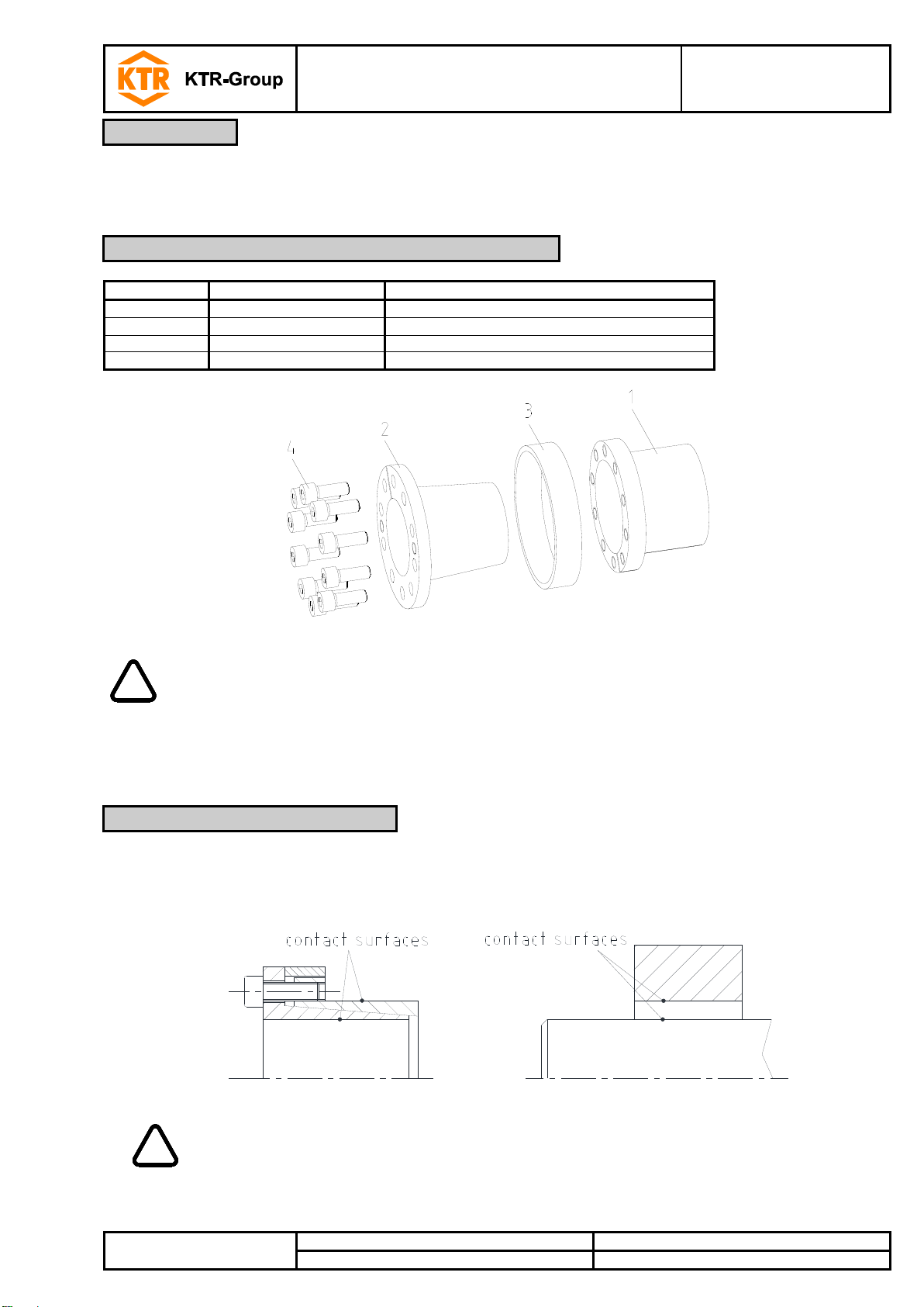
Illustration 2:Tolerances and surfaces (example: CLAMPEX®KTR 250)
1) One proper turning process
is sufficient (Rz ≤16 µm).
2) Highest permissible
tolerance of hub or shaft.
Please read through these operating/assembly instructions carefully before you mount the clamping set.
Please pay special attention to the safety instructions!
The operating/assembly instructions are part of your product. Please store them carefully and close to the
clamping set. The copyright for these operating/assembly instructions remains with KTR.
Warning of potentially explosive
atmospheres
This symbol indicates notes which may contribute to
preventing bodily injuries or serious bodily injuries that
may result in death caused by explosion.
STOP
Warning of personal injury
This symbol indicates notes which may contribute to
preventing bodily injuries or serious bodily injuries that
may result in death.
!
Warning of product damages
This symbol indicates notes which may contribute to
preventing material or machine damage.
General advice
This symbol indicates notes which may contribute to
preventing adverse results or conditions.
STOP
With assembly and disassembly of the clamping set it has to be made sure that the entire
drive train is secured against accidental switch-on. You may be seriously hurt by rotating
parts. Please make absolutely sure to read through and observe the following safety
indications.
•All operations on and with the clamping set have to be performed taking into account "safety first".
•Please make sure to switch off the power pack before you perform your work on the clamping set.
•Secure the power pack against accidental switch-on, e. g. by providing warning signs at the place of switch-on
or removing the fuse for current supply.
•Do not reach into the operation area of the machine as long as it is in operation.
•Please secure the rotating drive components against accidental contact. Please provide for the necessary
protection devices and covers.
1 Technical data
2 Advice
2.1 General advice
2.2 Safety and advice symbols
2.3 General hazard warnings

CLAMPEX®KTR 250
Operating/Assembly instructions
KTR-N
Sheet:
Edition:
40817 EN
4 of 7
6
Please observe protection
note ISO 16016.
Drawn:
2016-09-09 Shg/Jh
Replacing:
KTR-N dated 2011-05-23
Verified:
2016-09-09 Shg
Replaced by:
You may only assemble and disassemble the clamping set if you
•have carefully read through the operating/assembly instructions and understood them
•had technical training
•are authorized by your company
The clamping set may only be used in accordance with the technical data (see table 1). Unauthorized
modifications on the clamping set are not admissible. We will not assume liability for any damage that may arise.
In the interest of further development we reserve the right for technical modifications.
The clamping set described in here corresponds to the technical status at the time of printing of these
operating/assembly instructions.
The clamping sets are supplied in preserved condition and can be stored at a dry and roofed place for 6 - 9
months.
!
Humid storage rooms are not suitable.
Please make sure that condensation is not generated.
The clamping sets are packed differently each depending on size, quantity and kind of transport. Unless
otherwise contractually agreed, packaging will follow the in-house packaging specifications of KTR.
!
In order to avoid any injuries and any kind of damage please always make use of proper
transport and lifting equipment.
2 Advice
2.4 Intended use
3 Storage, transport and packaging
3.1 Storage
3.2 Transport and packaging

CLAMPEX®KTR 250
Operating/Assembly instructions
KTR-N
Sheet:
Edition:
40817 EN
5 of 7
6
Please observe protection
note ISO 16016.
Drawn:
2016-09-09 Shg/Jh
Replacing:
KTR-N dated 2011-05-23
Verified:
2016-09-09 Shg
Replaced by:
Generally the clamping set is supplied in mounted condition. Before assembly the clamping set has to be
inspected for completeness.
Component
Quantity
Description
1
1
Outer ring (slit)
2
1
Inner ring (slit)
3
1
Axial ring
4
see table 1
Cap screw DIN EN ISO 4762
Illustration 3: CLAMPEX®KTR 250
!
With assembly none of the pull-off threads of the internal ring may be congruent with the
slot of the external ring.
Dirty or used clamping sets have to be disassembled and cleaned before assembly.
Afterwards apply thin fluid oil lightly (e. g. Ballistol Universal oil or Klüber Quietsch-Ex).
1. Please inspect shaft and hub fit for the tolerance specified (h8/H8).
2. Clean the contact surfaces of the clamping set and of shaft and hub and afterwards apply thin fluid oil lightly
(see illustration 4) (e. g. Ballistol Universal oil or Klüber Quietsch-Ex).
Illustration 4: Cleaning the contact surfaces
!
Oils and greases with molybdenum disulphide or high-pressure additives, additives of
Teflon and silicone as well as internal lubricants reducing the coefficient of friction
significantly must not be used. When mounting the tapers of the clamping set free from oil
the tabular and calculated parameters deviate.
4 Assembly
4.1 Components of clamping set CLAMPEX®KTR 250
4.2 Assembly of the clamping set

CLAMPEX®KTR 250
Operating/Assembly instructions
KTR-N
Sheet:
Edition:
40817 EN
6 of 7
6
Please observe protection
note ISO 16016.
Drawn:
2016-09-09 Shg/Jh
Replacing:
KTR-N dated 2011-05-23
Verified:
2016-09-09 Shg
Replaced by:
3. Release the clamping screws slightly. To facilitate the assembly fasten the internal and external ring by two
clamping screws each via the pull-off threads (see illustration 5). Insert the clamping set KTR 250 between
shaft and hub.
Illustration 5: Fastening the clamping set KTR 250
4. Remove the clamping screws used for fastening and screw them into the threads of the external ring.
5. Lightly tighten the clamping screws manually and align the clamping set with hub part.
6. Make sure with KTR 250 that the axial back-up ring (component 3) fits the hub evenly.
7. Tighten the clamping screws evenly crosswise step by step to the tightening torque specified in table 1 or 2.
Repeat this process until all clamping screws have reached the tightening torque.
STOP
Driving components released or falling down may cause injury to persons or damage on the
machine.
Secure the driving components before disassembly.
1. Untighten and unscrew all clamping screws evenly and one after another.
2. Screw the clamping screws into the pull-off threads of the internal ring (component 2) (see illustration 6).
3. Tighten the clamping screws evenly crosswise by 1/4 revolution. Increase the pull-off torque gradually until the
external ring (component 1) and internal ring (component 2) are separated.
4. Take out the clamping set released between shaft and hub.
Illustration 6: Releasing the clamping set KTR 250
!
If these hints are not observed or operating conditions are not taken into account with the
selection of the clamping set, the operation of the clamping set may be affected.
4 Assembly
4.2 Assembly of the clamping set
4.3 Disassembly of clamping set

CLAMPEX®KTR 250
Operating/Assembly instructions
KTR-N
Sheet:
Edition:
40817 EN
7 of 7
6
Please observe protection
note ISO 16016.
Drawn:
2016-09-09 Shg/Jh
Replacing:
KTR-N dated 2011-05-23
Verified:
2016-09-09 Shg
Replaced by:
In respect of environmental protection we would ask you to dispose of the packaging or products on termination of
their service life in accordance with the legal regulations and standards that apply, respectively.
All clamping sets consist of metal. Any metal components have to be cleaned and disposed of by scrap metal.
A basic requirement to ensure the readiness for use of the drive components is a stock of some clamping sets on
site.
Contact addresses of the KTR partners for spare parts and orders can be obtained from the KTR homepage at
www.ktr.com.
KTR does not assume any liability or warranty for the use of spare parts and accessories
which are not provided by KTR and for the damages which may incur as a result.
If used in hazardous locations the type and size of clamping set (for category 3 only) has to be selected such that
the difference between the peak torque of the machine including all operating parameters and the rated torque of
the clamping hub at least corresponds to a safety factor of s = 2.0.
CLAMPEX®clamping sets are not part of directive 2014/34/EU, since
•this product is a torsionally rigid, backlash-free, frictionally engaged connection with one or more taper
clamping ring(s) ensured by several screws.
(Clamping screws have to be secured, e. g. by means of a medium strength adhesive.)
•due to the design of clamping sets a fracture/failure is not likely (frictional heat is only caused by improper
assembly/tightening torques, i. e. not with intended use).
5 Disposal
6 Spares inventory, customer service addresses
7 Advice regarding the use in hazardous locations according to EU directive
2014/34/EU
Table of contents
Other KTR-Group Power Tools manuals
Popular Power Tools manuals by other brands

Adkins
Adkins BETA MAJOR Operator's handbook

Jet
Jet JDP-17FSE owner's manual

Schwamborn
Schwamborn BEF 201 operating instructions

TYROLIT Hydrostress
TYROLIT Hydrostress HCE150 Original Operating Instruction

Black & Decker
Black & Decker JS500 instruction manual

Greenlee
Greenlee GREENLEE KWIK-STRIPPER 45019 instructions