KTR Kupplungstechnik
GmbH
D-48407 Rheine
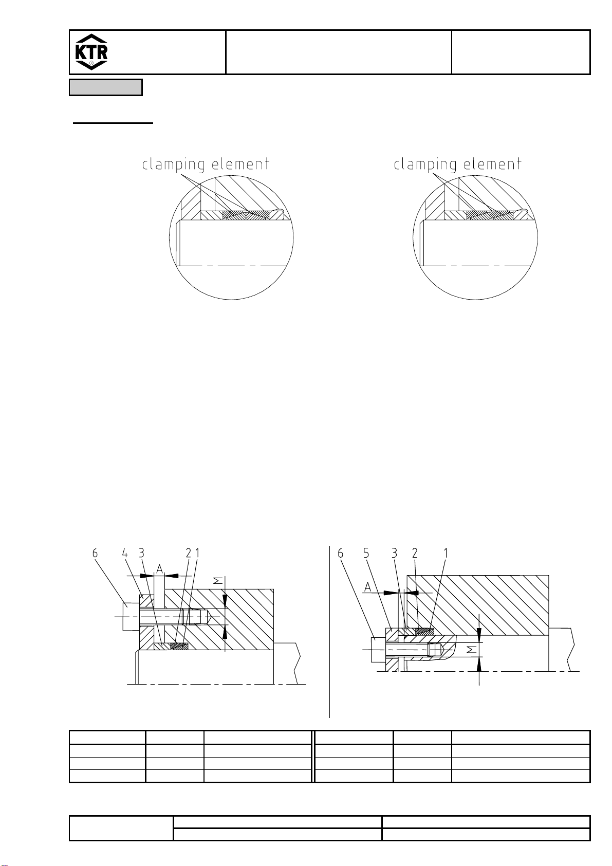
CLAMPEX®KTR 150
mounting instructions
KTR-N
sheet:
edition:
40812 E
4
5
Gezeichnet: 23.06.05 Sha/Hg Ersatz für: KTR-N 40815Schutzvermerk
ISO 16016 beachten. Geprüft: 21.07.05 Sha Ersetzt durch:
Assembly
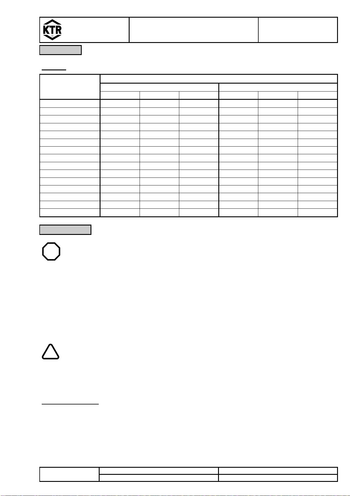
Table 1:
prestress power FVand tightening torque TAwith µges. = 0,14
prestress power FV[N] tightening torque TA[Nm]
dimensions
M 8.8 10.9 12.9 8.8 10.9 12.9
M3 2210 3110 3730 1,34 1,89 2,25
M4 3900 5450 6550 2,9 4,1 4,9
M5 6350 8950 10700 6 8,5 10
M6 9000 12600 15100 10 14 17
M8 16500 23200 27900 25 35 41
M10 26200 36900 44300 49 69 83
M12 38300 54000 64500 86 120 145
M14 52500 74000 88500 135 190 230
M16 73000 102000 123000 210 295 355
M18 88000 124000 148000 290 405 485
M20 114000 160000 192000 410 580 690
M22 141000 199000 239000 550 780 930
M24 164000 230000 276000 710 1000 1200
M27 215000 302000 363000 1050 1500 1800
M30 262000 368000 442000 1450 2000 2400
Disassembly
STOP
DANGER!
Loosened or falling drive parts can cause injuries to persons or damages to the
machines.
Safe the drive parts before the disassembly.
•Loose all clamping screws evenly one after the other and unscrew them.
•The clamping elements are not self-locking. If the inner and the outer taper rings are still stuck, the
detaching process can be started by a slight pressure onto the hub part at several places of the
circumference or the hub.
•Remove the detached clamping elements between shaft and hub.
! CAUTION!
In case of non-observance of these hints or in case of non-considerance of the
operating conditions regarding the selection of the clamping element, the function
of the clamping element can be influenced.
Disposal of waste: Defective clamping elements must be cleaned and scrapped.