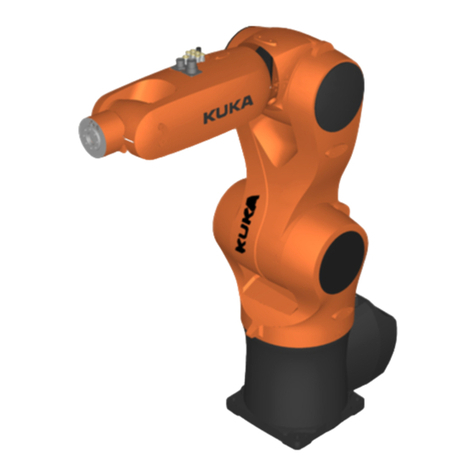
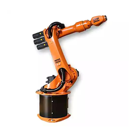
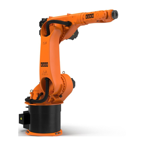
Kuka IONTEC KR 20 R3100 User manual

Robots
KR IONTEC
With F Variants
Assembly Instructions
Issued: 11.05.2021
MA KR IONTEC V4
KUKA Deutschland GmbH

KR IONTEC
2/344 | www.kuka.com MA KR IONTEC V4 | Issued: 11.05.2021
© Copyright 2021
KUKA Deutschland GmbH
Zugspitzstraße 140
D-86165 Augsburg
Germany
This documentation or excerpts therefrom may not be reproduced or disclosed to third parties
without the express permission of KUKA Deutschland GmbH.
Other functions not described in this documentation may be operable in the controller. The user
has no claims to these functions, however, in the case of a replacement or service work.
We have checked the content of this documentation for conformity with the hardware and soft-
ware described. Nevertheless, discrepancies cannot be precluded, for which reason we are not
able to guarantee total conformity. The information in this documentation is checked on a regu-
lar basis, however, and necessary corrections will be incorporated in the subsequent edition.
Subject to technical alterations without an effect on the function.
KIM-PS5-DOC
Translation of the original documentation
Publication: Pub MA KR IONTEC (PDF) en
PB14091
Book structure: MA KR IONTEC V6.3
BS12700
Version: MA KR IONTEC V4

Contents
1 Introduction.............................................................................................. 9
1.1 Target group.......................................................................................................... 9
1.2 Industrial robot documentation.............................................................................. 9
1.3 Representation of warnings and notes................................................................. 9
1.4 Terms used............................................................................................................ 10
2 Product description................................................................................. 15
2.1 Description of the robot system............................................................................ 15
2.2 Description of the manipulator.............................................................................. 16
2.3 Intended use and misuse...................................................................................... 17
3 Safety......................................................................................................... 19
3.1 General.................................................................................................................. 19
3.1.1 Disclaimer.............................................................................................................. 19
3.1.2 EC declaration of conformity and declaration of incorporation............................ 20
3.1.3 Terms in the “Safety” chapter............................................................................... 20
3.2 Personnel............................................................................................................... 22
3.3 Workspace, safety zone and danger zone........................................................... 23
3.4 Overview of protective equipment........................................................................ 23
3.4.1 Mechanical end stops........................................................................................... 24
3.4.2 Mechanical axis limitation (optional)..................................................................... 24
3.4.3 Options for moving the manipulator without drive energy................................... 24
3.4.4 Labeling on the industrial robot............................................................................ 25
3.5 Safety measures.................................................................................................... 25
3.5.1 General safety measures...................................................................................... 25
3.5.2 Transportation........................................................................................................ 27
3.5.3 Start-up and recommissioning.............................................................................. 27
3.5.4 Manual mode......................................................................................................... 29
3.5.5 Automatic mode..................................................................................................... 30
3.5.6 Maintenance and repair........................................................................................ 30
3.5.7 Decommissioning, storage and disposal.............................................................. 32
4 Technical data.......................................................................................... 33
4.1 Technical data, overview....................................................................................... 33
4.2 Technical data, KR 20 R3100............................................................................... 34
4.2.1 Basic data, KR 20 R3100..................................................................................... 34
4.2.2 Axis data, KR 20 R3100....................................................................................... 36
4.2.3 Payloads, KR 20 R3100....................................................................................... 39
4.2.4 Foundation loads, KR 20 R3100.......................................................................... 45
4.3 Technical data, KR 30 R2100............................................................................... 47
4.3.1 Basic data, KR 30 R2100..................................................................................... 47
4.3.2 Axis data, KR 30 R2100....................................................................................... 48
4.3.3 Payloads, KR 30 R2100....................................................................................... 51
4.3.4 Foundation loads, KR 30 R2100.......................................................................... 58
4.4 Technical data, KR 50 R2100............................................................................... 60
4.4.1 Basic data, KR 50 R2100..................................................................................... 60
4.4.2 Axis data, KR 50 R2100....................................................................................... 61
KR IONTEC
MA KR IONTEC V4 | Issued: 11.05.2021 www.kuka.com | 3/344

4.4.3 Payloads, KR 50 R2100....................................................................................... 64
4.4.4 Foundation loads, KR 50 R2100.......................................................................... 71
4.5 Technical data, KR 50 R2500............................................................................... 73
4.5.1 Basic data, KR 50 R2500..................................................................................... 73
4.5.2 Axis data, KR 50 R2500....................................................................................... 74
4.5.3 Payloads, KR 50 R2500....................................................................................... 78
4.5.4 Foundation loads, KR 50 R2500.......................................................................... 84
4.6 Technical data, KR 50 R2500 F........................................................................... 86
4.6.1 Basic data, KR 50 R2500 F................................................................................. 86
4.6.2 Axis data, KR 50 R2500 F................................................................................... 88
4.6.3 Payloads, KR 50 R2500 F.................................................................................... 92
4.6.4 Foundation loads, KR 50 R2500 F....................................................................... 98
4.7 Technical data, KR 70 R2100............................................................................... 100
4.7.1 Basic data, KR 70 R2100..................................................................................... 100
4.7.2 Axis data, KR 70 R2100....................................................................................... 101
4.7.3 Payloads, KR 70 R2100....................................................................................... 104
4.7.4 Foundation loads, KR 70 R2100.......................................................................... 111
4.8 Technical data, KR 70 R2100 F........................................................................... 113
4.8.1 Basic data, KR 70 R2100 F................................................................................. 113
4.8.2 Axis data, KR 70 R2100 F................................................................................... 115
4.8.3 Payloads, KR 70 R2100 F.................................................................................... 118
4.8.4 Foundation loads, KR 70 R2100 F....................................................................... 124
4.9 Plates and labels................................................................................................... 126
4.10 REACH duty to communicate information acc. to Art. 33................................... 128
4.11 Stopping distances and times............................................................................... 128
4.11.1 General information............................................................................................... 128
4.11.2 Stopping distances and times, KR 20 R3100...................................................... 129
4.11.2.1 Stopping distances and stopping times, STOP 0, A1 to A3............................... 129
4.11.2.2 Stopping distances and stopping times, STOP 1, A1.......................................... 130
4.11.2.3 Stopping distances and stopping times, STOP 1, A2.......................................... 132
4.11.2.4 Stopping distances and stopping times, STOP 1, A3.......................................... 134
4.11.3 Stopping distances and times, KR 30 R2100...................................................... 134
4.11.3.1 Stopping distances and stopping times, STOP 0, A1 to A3............................... 134
4.11.3.2 Stopping distances and stopping times, STOP 1, A1.......................................... 136
4.11.3.3 Stopping distances and stopping times, STOP 1, A2.......................................... 138
4.11.3.4 Stopping distances and stopping times, STOP 1, A3.......................................... 140
4.11.4 Stopping distances and times, KR 50 R2100...................................................... 140
4.11.4.1 Stopping distances and stopping times, STOP 0, A1 to A3............................... 140
4.11.4.2 Stopping distances and stopping times, STOP 1, A1.......................................... 142
4.11.4.3 Stopping distances and stopping times, STOP 1, A2.......................................... 144
4.11.4.4 Stopping distances and stopping times, STOP 1, A3.......................................... 146
4.11.5 Stopping distances and times, KR 50 R2500 and KR 50 R2500 F................... 146
4.11.5.1 Stopping distances and stopping times, STOP 0, A1 to A3............................... 146
4.11.5.2 Stopping distances and stopping times, STOP 1, A1.......................................... 148
4.11.5.3 Stopping distances and stopping times, STOP 1, A2.......................................... 150
4.11.5.4 Stopping distances and stopping times, STOP 1, A3.......................................... 152
4.11.6 Stopping distances and times, KR 70 R2100 and KR 70 R2100 F................... 152
4.11.6.1 Stopping distances and stopping times, STOP 0, A1 to A3............................... 152
4.11.6.2 Stopping distances and stopping times, STOP 1, A1.......................................... 154
KR IONTEC
4/344 | www.kuka.com MA KR IONTEC V4 | Issued: 11.05.2021
4.11.6.3 Stopping distances and stopping times, STOP 1, A2.......................................... 156
4.11.6.4 Stopping distances and stopping times, STOP 1, A3.......................................... 158
5 Planning.................................................................................................... 159
5.1 Information for planning........................................................................................ 159
5.2 Mounting base with centering............................................................................... 159
5.3 Machine frame mounting....................................................................................... 161
5.4 Connecting cables and interfaces......................................................................... 163
6 Transportation.......................................................................................... 167
6.1 Transporting the robot........................................................................................... 167
7 Start-up and recommissioning............................................................... 171
7.1 Overview of start-up and recommissioning.......................................................... 171
7.2 Starting up robots (mounting base)...................................................................... 171
7.2.1 Installing KR IONTEC fork slots........................................................................... 173
7.2.2 Installing the robot with a mounting base............................................................ 173
7.2.3 Removing KR IONTEC fork slots......................................................................... 176
7.2.4 Connecting the connecting cables........................................................................ 177
7.2.5 Concluding work.................................................................................................... 177
7.3 Starting up robots (machine frame mounting)...................................................... 178
7.3.1 Installing KR IONTEC fork slots........................................................................... 180
7.3.2 Installing the machine frame mounting assembly................................................ 180
7.3.3 Removing KR IONTEC fork slots......................................................................... 181
7.3.4 Connecting the connecting cables........................................................................ 182
7.3.5 Concluding work.................................................................................................... 183
7.4 Description of the connecting cables.................................................................... 183
7.5 Description of overtravel protection on axis 4...................................................... 187
8 Maintenance.............................................................................................. 189
8.1 Maintenance overview........................................................................................... 189
8.1.1 Maintenance table, KR IONTEC KR 20 R3100................................................... 190
8.1.2 Maintenance table, KR IONTEC standard and Foundry variants........................ 192
8.2 Greasing cable set A1.......................................................................................... 195
8.2.1 Checking and greasing cable set A1................................................................... 196
8.2.2 Concluding work.................................................................................................... 197
8.3 Oil change in A1................................................................................................... 197
8.3.1 Draining the gear oil from A1............................................................................... 198
8.3.2 Filling gear unit A1 with gear oil........................................................................... 199
8.3.3 Concluding work.................................................................................................... 200
8.4 Oil change in A2................................................................................................... 200
8.4.1 Draining the gear oil from A2............................................................................... 201
8.4.2 Filling gear unit A2 with gear oil........................................................................... 202
8.4.3 Concluding work.................................................................................................... 203
8.5 Oil change in A3................................................................................................... 203
8.5.1 Draining the gear oil from A3............................................................................... 205
8.5.2 Filling gear unit A3 with gear oil........................................................................... 205
8.5.3 Concluding work.................................................................................................... 206
8.6 Oil change in A4................................................................................................... 206
8.6.1 Draining the gear oil from A4............................................................................... 208
KR IONTEC
MA KR IONTEC V4 | Issued: 11.05.2021 www.kuka.com | 5/344

8.6.2 Filling gear unit A4 with gear oil........................................................................... 208
8.6.3 Concluding work.................................................................................................... 209
8.7 Oil change in A5................................................................................................... 210
8.7.1 Draining the gear oil from A5............................................................................... 211
8.7.2 Filling gear unit A5 with gear oil........................................................................... 212
8.7.3 Concluding work.................................................................................................... 213
8.8 Oil change in A6................................................................................................... 213
8.8.1 Draining the gear oil from A6............................................................................... 215
8.8.2 Filling gear unit A6 with gear oil........................................................................... 215
8.8.3 Concluding work.................................................................................................... 217
8.9 KR 20 R3100......................................................................................................... 217
8.9.1 Oil change in A4 .................................................................................................. 217
8.9.1.1 Draining the gear oil from A4............................................................................... 218
8.9.1.2 Filling gear unit A4 with gear oil........................................................................... 219
8.9.1.3 Concluding work.................................................................................................... 220
8.9.2 Oil change in A5................................................................................................... 220
8.9.2.1 Draining the gear oil from A5............................................................................... 222
8.9.2.2 Filling gear unit A5 with gear oil........................................................................... 223
8.9.2.3 Concluding work.................................................................................................... 223
8.9.3 Oil change in A6................................................................................................... 223
8.9.3.1 Draining the gear oil from A6............................................................................... 225
8.9.3.2 Filling gear unit A6 with gear oil........................................................................... 226
8.9.3.3 Concluding work.................................................................................................... 227
8.10 Cleaning the robot................................................................................................. 227
8.10.1 Cleaning................................................................................................................. 228
8.10.2 Concluding work.................................................................................................... 228
9 Repair........................................................................................................ 229
9.1 Exchanging motor A1............................................................................................ 229
9.1.1 Removing motor A1.............................................................................................. 230
9.1.2 Installing motor A1................................................................................................ 231
9.1.3 Concluding work.................................................................................................... 232
9.2 Exchanging motor A2............................................................................................ 233
9.2.1 Securing the link arm............................................................................................ 235
9.2.2 Removing motor A2.............................................................................................. 235
9.2.3 Installing motor A2................................................................................................ 236
9.2.4 Removing the equipment securing the link arm.................................................. 237
9.2.5 Concluding work.................................................................................................... 238
9.3 Exchanging motor A3............................................................................................ 238
9.3.1 Securing the in-line wrist and robot arm.............................................................. 240
9.3.2 Removing cover A3............................................................................................... 241
9.3.3 Removing motor A3.............................................................................................. 242
9.3.4 Installing motor A3................................................................................................ 243
9.3.5 Mounting the cover................................................................................................ 244
9.3.6 Removing the equipment securing the in-line wrist and robot arm..................... 245
9.3.7 Concluding work.................................................................................................... 246
9.4 KR IONTEC Foundry............................................................................................ 246
9.4.1 Exchanging motor A1............................................................................................ 246
9.4.1.1 Removing motor A1.............................................................................................. 248
KR IONTEC
6/344 | www.kuka.com MA KR IONTEC V4 | Issued: 11.05.2021
9.4.1.2 Installing motor A1................................................................................................ 249
9.4.1.3 Concluding work.................................................................................................... 250
9.4.2 Exchanging motor A2............................................................................................ 251
9.4.2.1 Securing the link arm............................................................................................ 252
9.4.2.2 Removing motor A2.............................................................................................. 253
9.4.2.3 Installing motor A2................................................................................................ 254
9.4.2.4 Removing the equipment securing the link arm.................................................. 255
9.4.2.5 Concluding work.................................................................................................... 256
9.5 KR 20 R3100......................................................................................................... 256
9.5.1 Exchanging motor A4............................................................................................ 256
9.5.1.1 Securing the in-line wrist and robot arm.............................................................. 258
9.5.1.2 Removing cover A3............................................................................................... 259
9.5.1.3 Removing motor A4.............................................................................................. 260
9.5.1.4 Installing motor A4................................................................................................ 261
9.5.1.5 Mounting the cover................................................................................................ 262
9.5.1.6 Removing the equipment securing the in-line wrist and robot arm..................... 263
9.5.1.7 Concluding work.................................................................................................... 264
9.5.2 Exchanging motor A5............................................................................................ 264
9.5.2.1 Securing the in-line wrist and robot arm.............................................................. 266
9.5.2.2 Removing cover A3............................................................................................... 267
9.5.2.3 Removing motor A5.............................................................................................. 268
9.5.2.4 Installing motor A5................................................................................................ 269
9.5.2.5 Mounting the cover................................................................................................ 270
9.5.2.6 Removing the equipment securing the in-line wrist and robot arm..................... 271
9.5.2.7 Concluding work.................................................................................................... 272
9.5.3 Exchanging motor A6 and in-line wrist................................................................. 272
9.5.3.1 Securing the in-line wrist and robot arm.............................................................. 274
9.5.3.2 Removing cover A3............................................................................................... 275
9.5.3.3 Removing motor A4.............................................................................................. 276
9.5.3.4 Removing motor A5.............................................................................................. 277
9.5.3.5 Removing motor A6 and in-line wrist................................................................... 278
9.5.3.6 Preparing the new in-line wrist............................................................................. 278
9.5.3.7 Installing motor A6 and in-line wrist..................................................................... 279
9.5.3.8 Installing motor A5................................................................................................ 280
9.5.3.9 Installing motor A4................................................................................................ 281
9.5.3.10 Mounting the cover................................................................................................ 283
9.5.3.11 Removing the equipment securing the in-line wrist and robot arm..................... 284
9.5.3.12 Concluding work.................................................................................................... 285
9.5.4 Exchanging the connecting shafts........................................................................ 285
9.5.4.1 Securing the in-line wrist and robot arm.............................................................. 287
9.5.4.2 Removing cover A3............................................................................................... 288
9.5.4.3 Removing motor A4.............................................................................................. 289
9.5.4.4 Removing motor A5.............................................................................................. 290
9.5.4.5 Installing motor A5................................................................................................ 291
9.5.4.6 Installing motor A4................................................................................................ 292
9.5.4.7 Mounting the cover................................................................................................ 294
9.5.4.8 Removing the equipment securing the in-line wrist and robot arm..................... 295
9.5.4.9 Concluding work.................................................................................................... 296
9.6 Description of the electrical installations.............................................................. 296
KR IONTEC
MA KR IONTEC V4 | Issued: 11.05.2021 www.kuka.com | 7/344
10 Decommissioning, storage and disposal............................................. 311
10.1 Decommissioning................................................................................................... 311
10.1.1 Moving the robot into its transport position.......................................................... 311
10.1.2 Removing the robot............................................................................................... 312
10.1.3 Concluding work.................................................................................................... 313
10.2 Storage.................................................................................................................. 313
10.2.1 Removing the robot............................................................................................... 315
10.2.2 Cleaning................................................................................................................. 316
10.2.3 Preparing for storage............................................................................................ 316
10.2.4 Concluding work.................................................................................................... 316
10.3 Disposal................................................................................................................. 316
11 Options...................................................................................................... 319
11.1 Release device...................................................................................................... 319
11.1.1 Starting up the release device.............................................................................. 319
11.1.1.1 Installing the release device................................................................................. 320
11.1.1.2 Moving the manipulator without drive energy...................................................... 322
11.1.1.3 Concluding work.................................................................................................... 324
11.2 Purge option A...................................................................................................... 324
11.3 Purge option B...................................................................................................... 325
11.4 Purge option C...................................................................................................... 327
11.4.1 Starting up PURGE option C................................................................................ 328
11.4.1.1 Installing PURGE option C................................................................................... 329
11.4.1.2 Concluding work.................................................................................................... 330
11.5 Purge option D...................................................................................................... 331
11.5.1 Starting up PURGE option D................................................................................ 332
11.5.1.1 Installing PURGE option D................................................................................... 333
11.5.1.2 Concluding work.................................................................................................... 334
12 Appendix................................................................................................... 335
12.1 Tightening torques................................................................................................. 335
12.2 Auxiliary and operating materials used................................................................ 336
12.3 Applied standards and regulations....................................................................... 337
13 KUKA Service........................................................................................... 339
13.1 Requesting support............................................................................................... 339
13.2 KUKA Customer Support...................................................................................... 339
Index 341
KR IONTEC
8/344 | www.kuka.com MA KR IONTEC V4 | Issued: 11.05.2021
1 Introduction
1.1 Target group
This documentation is aimed at users with the following knowledge and
skills:
• Advanced knowledge of mechanical engineering
• Advanced knowledge of electrical engineering
• Knowledge of the robot controller system
For optimal use of KUKA products, we recommend the training courses
offered by KUKA College. Information about the training program can be
found at www.kuka.com or can be obtained directly from our subsidia-
ries.
1.2 Industrial robot documentation
The industrial robot documentation consists of the following parts:
• Documentation for the robot arm
• Documentation for the robot controller
• Documentation for the smartPAD-2 (if used)
• Operating and programming instructions for the System Software
• Instructions for options and accessories
• Spare parts overview in KUKA Xpert
Each of these sets of instructions is a separate document.
1.3 Representation of warnings and notes
Safety
These warnings are provided for safety purposes and must be observed.
DANGER
These warnings mean that it is certain or highly probable that death or
severe injuries will occur, if no precautions are taken.
WARNING
These warnings mean that death or severe injuries may occur, if no
precautions are taken.
CAUTION
These warnings mean that minor injuries may occur, if no precautions
are taken.
NOTICE
These warnings mean that damage to property may occur, if no precau-
tions are taken.
These warnings contain references to safety-relevant information or gen-
eral safety measures.
These warnings do not refer to individual hazards or individual precau-
tionary measures.
KR IONTEC
MA KR IONTEC V4 | Issued: 11.05.2021 www.kuka.com | 9/344
Introduction

This warning draws attention to procedures which serve to prevent or rem-
edy emergencies or malfunctions:
SAFETY INSTRUCTION
The following procedure must be followed exactly!
Procedures marked with this warning must be followed exactly.
Notices
These notices serve to make your work easier or contain references to
further information.
Tip to make your work easier or reference to further information.
1.4 Terms used
The overview may contain terms symbols that are not relevant for this
document.
Term Description
Axis range Range of each axis, in degrees or millimeters, within which it may
move. The axis range must be defined for each axis.
Stopping distance Stopping distance = reaction distance + braking distance
The stopping distance is part of the danger zone.
Workspace Area within which the robot may move. The workspace is derived
from the individual axis ranges.
Arctic Arctic
for use in temperature ranges under 0°
Extension Distance (l in %) between axis 1 and the intersection of axes 4 and
5. With parallelogram robots, the distance between axis 1 and the
intersection of axis 6 and the mounting flange.
C Ceiling
CR Clean Room
Designation for KUKA products developed for use in cleanrooms.
EDS Electronic Data Storage
(memory card)
EMD Electronic Mastering Device
SPP Spare parts package
KR IONTEC
10/344 | www.kuka.com MA KR IONTEC V4 | Issued: 11.05.2021
Introduction

EX Explosion-proof zone
F Foundry
F exclusive Foundry exclusive
Danger zone The danger zone consists of the workspace and the stopping dis-
tances of the manipulator and external axes (optional).
HA High Accuracy
HM Hygienic Machine
For the primary and secondary foodstuffs industries
HO Hygienic Oil
For the secondary foodstuffs industry
HP High Protection
HW Hollow Wrist
K Shelf-mounted
KCP KUKA Control Panel
Teach pendant for the KR C2/KR C2 edition2005
The KCP has all the operator control and display functions required
for operating and programming the industrial robot.
KR KUKA robot
KR C KUKA Robot Control
Robot controller
KS Shelf-mounted, small
KUKA smartPAD see “smartPAD”
KUKA smartPAD-2 see “smartPAD”
Manipulator The robot arm and the associated electrical installations
MEMD Micro Electronic Mastering Device
micro RDC micro Resolver Digital Converter
MT Machine Tooling
P Press-to-press robot
PA Palletizer
Phi Angle of rotation (°) about the corresponding axis. This value can
be entered in the controller via the teach pendant, from which it
can be read.
POV Program override (%) = velocity of the robot motion. This value can
be entered in the controller via the teach pendant, from which it
can be read.
KR IONTEC
MA KR IONTEC V4 | Issued: 11.05.2021 www.kuka.com | 11/344

Introduction

RDC Resolver Digital Converter
The resolver digital converter is used to acquire motor data (e.g.
position data, motor temperatures).
SC Special Connection
SE Second Encoder
SI Safe Interaction
SL Washdown
smartPAD Programming device for the robot controller
The smartPAD has all the operator control and display functions re-
quired for operating and programming the industrial robot. 2 models
exist:
• smartPAD
• smartPAD-2
In turn, for each model there are variants, e.g. with different lengths
of connecting cables.
For robot controllers of the KR C5 series, only the model “smart-
PAD-2” is used.
For other robot controllers, the designation “KUKA smartPAD” or
“smartPAD” always refers to both models unless an explicit distinc-
tion is made.
Stop category 0 The drives are deactivated immediately and the brakes are applied.
The manipulator and any external axes (optional) perform path-ori-
ented braking.
Note: This stop category is called STOP 0 in this document.
Stop category 1 The manipulator and any external axes (optional) perform path-
maintaining braking.
• Operating mode T1: the drives are deactivated as soon as the
robot has stopped, but no later than after 680 ms.
• Operating modes T2, AUT (KR C controller), AUT EXT (KR C
controller), EXT (VKR C controller):
The drives are switched off after 1.5 s.
Note: This stop category is called STOP 1 in this document.
Stop category 1 –
Drive Ramp Stop
The manipulator and any external axes (optional) perform path-ori-
ented braking.
• Operating mode T1: the drives are deactivated as soon as the
robot has stopped, but no later than after 680 ms.
• Operating modes T2, AUT (KR C controller), AUT EXT (KR C
controller), EXT (VKR C controller):
The drives are switched off after 1.5 s.
Note: This stop category is called STOP 1 - DRS in this document.
Stop category 2 The drives are not deactivated and the brakes are not applied. The
manipulator and any external axes (optional) are braked with a
path-maintaining braking ramp.
Note: This stop category is called STOP 2 in this document.
KR IONTEC
12/344 | www.kuka.com MA KR IONTEC V4 | Issued: 11.05.2021
Introduction

T1 Test mode, Manual Reduced Velocity (<= 250 mm/s)
T2 Test mode, Manual High Velocity (> 250 mm/s permissible)
W Wall
WP Waterproof
External axis Motion axis which is not part of the manipulator but is controlled by
the robot controller, e.g. KUKA linear unit, turn-tilt table, positioner.
KR IONTEC
MA KR IONTEC V4 | Issued: 11.05.2021 www.kuka.com | 13/344
Introduction

KR IONTEC
14/344 | www.kuka.com MA KR IONTEC V4 | Issued: 11.05.2021
Introduction

2 Product description
2.1 Description of the robot system
A robot system (>>> Fig. 2-1) comprises all the assemblies of an industri-
al robot, including the manipulator (mechanical system and electrical in-
stallations), robot controller, connecting cables, tool and other equipment.
The KR IONTEC product family comprises the following robot variants:
• KR 20 R3100
• KR 30 R2100
• KR 50 R2100
• KR 50 R2500
• KR 50 R2500 F
• KR 70 R2100
• KR 70 R2100 F
An industrial robot of this product family comprises the following compo-
nents:
• Manipulator
• Connecting cables
• Robot controller
• Teach pendant (KUKA smartPAD)
• Software
• Options, accessories
Fig. 2-1: Example of an industrial robot
1 Manipulator
2 Connecting cables
3 Robot controller
4 Teach pendant, KUKA smartPAD
KR IONTEC
MA KR IONTEC V4 | Issued: 11.05.2021 www.kuka.com | 15/344
Product description

2.2 Description of the manipulator
Overview
The manipulators (robot arm and electrical installations) (>>> Fig. 2-2) of
the KR IONTEC robot family are designed as 6-axis jointed-arm kinematic
systems. They consist of the following principal components:
Fig. 2-2: Main assemblies of the manipulator
1 In-line wrist/arm
2 Link arm
3 Rotating column
4 Base frame
5 Electrical installations
Axes 1 to 3 are equipped with end stops. These serve only as machine
protection. There are two options available for personnel protection:
• The Safe Robot functionality of the controller
• The use of mechanical axis limitations for axes 1 to 3 (optional).
In-line wrist/arm
The robot is equipped with a three-axis in-line wrist / arm combination.
This in-line wrist / arm combination is screwed directly to the link arm of
the robot via gear unit A3. End effectors are attached to the mounting
flange of axis 6. Axes A1 to A6 have a measuring device, through which
the mechanical zero of the respective axis can be checked by means of
an electronic probe (MEMD) and transferred to the controller. Directions of
rotation, axis data and permissible loads can be found in the chapter
(>>> 4 "Technical data" Page 33). The in-line wrist is driven by the mo-
tors inside the in-line wrist.
There is an interface on the arm for fastening supplementary loads.
The mounting flange conforms, with minimal deviations, to ISO 9409-1:
2004
KR IONTEC
16/344 | www.kuka.com MA KR IONTEC V4 | Issued: 11.05.2021
Product description

Link arm
The link arm is the assembly located between the arm and the rotating
column. There are two length variants of the link arm available. There is
an interface on the link arm for fastening supplementary loads.
Rotating column
The rotating column houses the gear units and motors A1 and A2. The ro-
tational motion of axis 1 is performed by the rotating column. This is
screwed to the base frame via the gear unit of axis 1 and is driven by a
motor in the rotating column. The link arm is also mounted in the rotating
column.
There is an interface on the rotating column for fastening supplementary
loads.
Base frame
The base frame is the base of the robot. It is screwed to the mounting
base. The electrical installations are fastened in the base frame. Also lo-
cated on the base frame is the interface for the motor and data cable and
the energy supply system.
Electrical installations
The electrical installations include all the motor and data cables for the
motors of axes 1 to 6. The complete electrical installations consist of ca-
ble set A1 - A3 and cable set A4 - A6.
All connections are implemented as connectors in order to enable the
main axis motors to be exchanged quickly and reliably. The electrical in-
stallations also include a protective circuit. The ground conductors to the
robot are connected to the base frame by means of ring cable lugs and
setscrews.
Options
The robot can be equipped with the following options. The options are de-
scribed in separate documentation or in these assembly instructions.
• Axis limitations A1, A2 and A3
• Adapter ring
• Booster frame
• Brake release device
• Energy supply system A1 to A3
• Energy supply system A3 to A6
• Release device (>>> 11.1 "Release device" Page 319)
• Purge option A (>>> 11.2 "Purge option A" Page 324)
• Purge option B (>>> 11.3 "Purge option B" Page 325)
• Purge option C (>>> 11.4 "Purge option C" Page 327)
• Purge option D (>>> 11.5 "Purge option D" Page 331)
• Fork slots
2.3 Intended use and misuse
Intended use
The industrial robot is intended for handling tools and fixtures or for pro-
cessing and transferring components or products. Use is only permitted
under the specified environmental conditions.
KR IONTEC
MA KR IONTEC V4 | Issued: 11.05.2021 www.kuka.com | 17/344
Product description

Operation of the industrial robot in accordance with its intended use also
requires compliance with the operating and assembly instructions for the
individual components, with particular reference to the maintenance speci-
fications.
Misuse
Any use or application deviating from the intended use is deemed to be
misuse and is not allowed. It will result in the loss of warranty and liability
claims. KUKA is not liable for any damage resulting from such misuse.
This includes e.g.:
• Use as a climbing aid
• Operation outside the specified operating parameters
• Operation without the required safety equipment
• Transportation of persons and animals
• Outdoor operation.
• Use in a potentially explosive area
• Use in radioactive environments
• Operation in underground mining
NOTICE
Deviations from the operating conditions specified in the technical data
or the use of special functions or applications can lead to premature
wear. KUKA Deutschland GmbH must be consulted.
The robot system is an integral part of a complete system and may only
be operated in a CE-compliant system.
KR IONTEC
18/344 | www.kuka.com MA KR IONTEC V4 | Issued: 11.05.2021
Product description

3 Safety
3.1 General
• This “Safety” chapter refers to a mechanical component of an indus-
trial robot.
• If the mechanical component is used together with a KUKA robot
controller, the “Safety” chapter of the operating instructions or as-
sembly instructions of the robot controller must be used!
This contains all the information provided in this “Safety” chapter. It
also contains additional safety information relating to the robot con-
troller which must be observed.
• Where this “Safety” chapter uses the term “industrial robot”, this also
refers to the individual mechanical component if applicable.
3.1.1 Disclaimer
The device described in this document is either an industrial robot or a
component thereof.
Components of the industrial robot:
• Manipulator
• Robot controller
• Teach pendant
• Connecting cables
• External axes (optional)
e.g. linear unit, turn-tilt table, positioner
• Software
• Options, accessories
The industrial robot is built using state-of-the-art technology and in accord-
ance with the recognized safety rules. Nevertheless, misuse of the indus-
trial robot may constitute a risk to life and limb or cause damage to the
industrial robot and to other material property.
The industrial robot may only be used in perfect technical condition in ac-
cordance with its intended use and only by safety-conscious persons who
are fully aware of the risks involved in its operation. Use of the industrial
robot is subject to compliance with this document and with the declaration
of incorporation supplied together with the industrial robot. Any functional
disorders, especially those affecting safety, must be rectified immediately.
Safety information
Information about safety may not be construed against the manufacturer.
Even if all safety instructions are followed, this is not a guarantee that the
industrial robot will not cause personal injuries or material damage.
No modifications may be carried out to the industrial robot without the au-
thorization of the manufacturer. Unauthorized modifications will result in
the loss of warranty and liability claims.
Additional components (tools, software, etc.), not supplied by the manufac-
turer, may be integrated into the industrial robot. The user is liable for any
damage these components may cause to the industrial robot or to other
material property.
In addition to the Safety chapter, this document contains further safety in-
structions. These must also be observed.
KR IONTEC
MA KR IONTEC V4 | Issued: 11.05.2021 www.kuka.com | 19/344
Safety

3.1.2 EC declaration of conformity and declaration of incorporation
The industrial robot constitutes partly completed machinery as defined by
the EC Machinery Directive. The industrial robot may only be put into op-
eration if the following preconditions are met:
• The industrial robot is integrated into a complete system.
or: The industrial robot, together with other machinery, constitutes a
complete system.
or: All safety functions and safeguards required for operation in the
complete machine as defined by the EC Machinery Directive have
been added to the industrial robot.
• The complete system complies with the EC Machinery Directive. This
has been confirmed by means of a conformity assessment procedure.
EC declaration of conformity
The system integrator must issue an EC declaration of conformity for the
complete system in accordance with the Machinery Directive. The EC dec-
laration of conformity forms the basis for the CE mark for the system. The
industrial robot must always be operated in accordance with the applicable
national laws, regulations and standards.
The robot controller has a CE mark in accordance with the EMC Directive
and the Low Voltage Directive.
Declaration of incorporation
The partly completed machinery is supplied with a declaration of incorpo-
ration in accordance with Annex II B of the Machinery Directive
2006/42/EC. The assembly instructions and a list of essential require-
ments complied with in accordance with Annex I are integral parts of this
declaration of incorporation.
The declaration of incorporation declares that the start-up of the partly
completed machinery is not allowed until the partly completed machinery
has been incorporated into machinery, or has been assembled with other
parts to form machinery, and this machinery complies with the terms of
the EC Machinery Directive, and the EC declaration of conformity is
present in accordance with Annex II A.
3.1.3 Terms in the “Safety” chapter
Term Description
Axis range Range of each axis, in degrees or millimeters, within which it may
move. The axis range must be defined for each axis.
Stopping distance Stopping distance = reaction distance + braking distance
The stopping distance is part of the danger zone.
Workspace Area within which the robot may move. The workspace is derived
from the individual axis ranges.
User The user of the industrial robot can be the management, employer
or delegated person responsible for use of the industrial robot.
KR IONTEC
20/344 | www.kuka.com MA KR IONTEC V4 | Issued: 11.05.2021
Safety
This manual suits for next models
6
Table of contents
Other Kuka Robotics manuals

Kuka
Kuka KR 20-3 User manual

Kuka
Kuka KRC4 User manual

Kuka
Kuka Pulse Installation guide

Kuka
Kuka KR 300-2 PA User manual

Kuka
Kuka KR QUANTEC extra User manual

Kuka
Kuka KR 30-2 User manual

Kuka
Kuka KR AGILUS sixx User manual

Kuka
Kuka iiQKA LBR iisy User manual

Kuka
Kuka LBR iisy User manual

Kuka
Kuka ready2 educate User manual