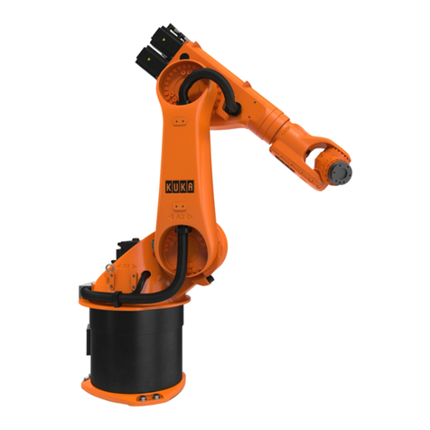
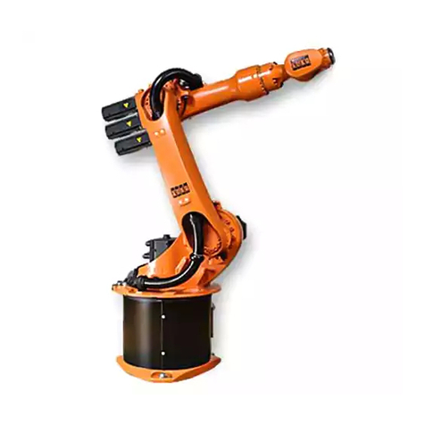
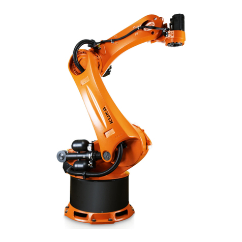
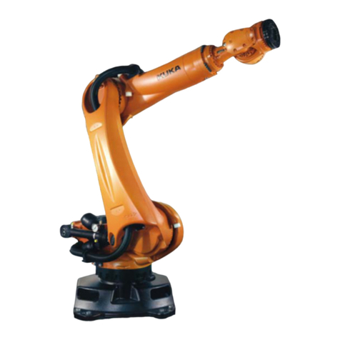
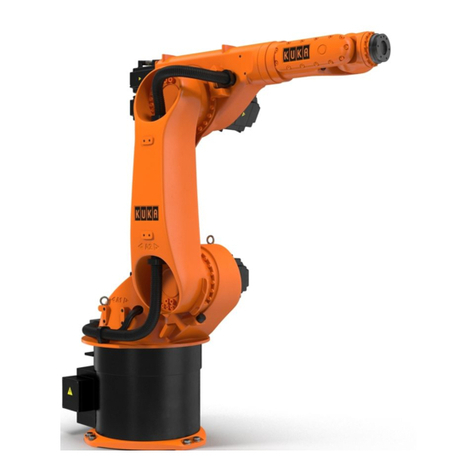
Kuka KR 30-2 User manual

Robots
KR 30-2 JET; KR 60-2 JET
Specification
KUKA Roboter GmbH
Issued: 08.09.2015
Version: Spez KR 30, 60-2 JET V1
KR 30-2 JET;
KR 60-2 JET

KR 30-2 JET; KR 60-2 JET
2 / 85 Issued: 08.09.2015 Version: Spez KR 30, 60-2 JET V1
© Copyright 2015
KUKA Roboter GmbH
Zugspitzstraße 140
D-86165 Augsburg
Germany
This documentation or excerpts therefrom may not be reproduced or disclosed to third parties without
the express permission of KUKA Roboter GmbH.
Other functions not described in this documentation may be operable in the controller. The user has
no claims to these functions, however, in the case of a replacement or service work.
We have checked the content of this documentation for conformity with the hardware and software
described. Nevertheless, discrepancies cannot be precluded, for which reason we are not able to
guarantee total conformity. The information in this documentation is checked on a regular basis, how-
ever, and necessary corrections will be incorporated in the subsequent edition.
Subject to technical alterations without an effect on the function.
Translation of the original documentation
KIM-PS5-DOC
Publication: Pub Spez KR 30, 60-2 JET (PDF) en
Book structure: Spez KR 30, 60-2 JET V1.2
Version: Spez KR 30, 60-2 JET V1

3 / 85Issued: 08.09.2015 Version: Spez KR 30, 60-2 JET V1
Contents
1 Introduction .................................................................................................. 5
1.1 Industrial robot documentation ................................................................................... 5
1.2 Representation of warnings and notes ...................................................................... 5
2 Purpose ........................................................................................................ 7
2.1 Target group .............................................................................................................. 7
2.2 Intended use .............................................................................................................. 7
3 Product description ..................................................................................... 9
3.1 Overview of the robot system .................................................................................... 9
3.2 Description of the robot .............................................................................................. 9
4 Technical data .............................................................................................. 13
4.1 Basic data ..................................................................................................................13
4.2 Basic data ..................................................................................................................14
4.3 Basic data ..................................................................................................................15
4.4 Basic data ..................................................................................................................16
4.5 Axis data .................................................................................................................... 17
4.6 Axis data .................................................................................................................... 19
4.7 Axis data .................................................................................................................... 21
4.8 Axis data .................................................................................................................... 23
4.9 Order-specific technical data ..................................................................................... 25
4.10 Payloads .................................................................................................................... 26
4.11 Payloads .................................................................................................................... 29
4.12 Payloads .................................................................................................................... 32
4.13 Payloads .................................................................................................................... 35
4.14 Foundation loads ....................................................................................................... 38
4.15 Plates and labels ........................................................................................................ 40
4.16 Stopping distances and times .................................................................................... 41
4.16.1 General information .............................................................................................. 41
4.16.2 Terms used ........................................................................................................... 42
4.16.3 Stopping distances and stopping times for STOP 0, axis 1 to axis 3 ................... 43
4.16.4 Stopping distances and stopping times for STOP 1, axis 1 .................................. 44
4.16.5 Stopping distances and stopping times for STOP 1, axis 2 .................................. 46
4.16.6 Stopping distances and stopping times for STOP 1, axis 3 .................................. 48
5 Safety ............................................................................................................ 49
5.1 General ...................................................................................................................... 49
5.1.1 Liability .................................................................................................................. 49
5.1.2 Intended use of the industrial robot ...................................................................... 50
5.1.3 EC declaration of conformity and declaration of incorporation ............................. 50
5.1.4 Terms used ........................................................................................................... 51
5.2 Personnel ...................................................................................................................51
5.3 Workspace, safety zone and danger zone ................................................................. 52
5.4 Overview of protective equipment .............................................................................. 53
5.4.1 Mechanical end stops ........................................................................................... 53
5.4.2 Mechanical axis range limitation (optional) ........................................................... 53
5.4.3 Axis range monitoring (optional) ........................................................................... 53
Contents
4 / 85 Issued: 08.09.2015 Version: Spez KR 30, 60-2 JET V1
KR 30-2 JET; KR 60-2 JET
5.4.4 Options for moving the manipulator without drive energy .................................... 54
5.4.5 Labeling on the industrial robot ............................................................................ 54
5.5 Safety measures ........................................................................................................ 55
5.5.1 General safety measures ..................................................................................... 55
5.5.2 Transportation ...................................................................................................... 56
5.5.3 Start-up and recommissioning .............................................................................. 56
5.5.4 Manual mode ........................................................................................................ 58
5.5.5 Automatic mode ................................................................................................... 58
5.5.6 Maintenance and repair ........................................................................................ 59
5.5.7 Decommissioning, storage and disposal .............................................................. 60
5.6 Applied norms and regulations .................................................................................. 60
6 Planning ........................................................................................................ 63
6.1 Information for planning ............................................................................................. 63
6.2 Mounting base ........................................................................................................... 63
6.3 Connecting cables and interfaces ............................................................................. 65
7 Transportation ............................................................................................. 67
7.1 Transportation ........................................................................................................... 67
8 Options ......................................................................................................... 73
8.1 Release device (optional) .......................................................................................... 73
9 KUKA Service ............................................................................................... 75
9.1 Requesting support ................................................................................................... 75
9.2 KUKA Customer Support ........................................................................................... 75
Index ............................................................................................................. 83

5 / 85Issued: 08.09.2015 Version: Spez KR 30, 60-2 JET V1
1 Introduction
1Introduction
1.1 Industrial robot documentation
The industrial robot documentation consists of the following parts:
Documentation for the manipulator
Documentation for the robot controller
Operating and programming instructions for the System Software
Instructions for options and accessories
Parts catalog on storage medium
Each of these sets of instructions is a separate document.
1.2 Representation of warnings and notes
Safety These warnings are relevant to safety and must be observed.
This warning draws attention to procedures which serve to prevent or remedy
emergencies or malfunctions:
Notices These notices serve to make your work easier or contain references to further
information.
t
t
These warnings mean that it is certain or highly probable
that death or severe injuries will occur, if no precautions
are taken.
These warnings mean that death or severe injuries may
occur, if no precautions are taken.
These warnings mean that minor injuries may occur, if
no precautions are taken.
These warnings mean that damage to property may oc-
cur, if no precautions are taken.
These warnings contain references to safety-relevant information or
general safety measures.
These warnings do not refer to individual hazards or individual pre-
cautionary measures.
Procedures marked with this warning must be followed
exactly.
Tip to make your work easier or reference to further information.

7 / 85Issued: 08.09.2015 Version: Spez KR 30, 60-2 JET V1
2 Purpose
2Purpose
2.1 Target group
This documentation is aimed at users with the following knowledge and skills:
Advanced knowledge of mechanical engineering
Advanced knowledge of electrical and electronic systems
Knowledge of the robot controller system
2.2 Intended use
Use The industrial robot is intended for handling tools and fixtures, or for process-
ing or transferring components or products. Use is only permitted under the
specified environmental conditions.
Misuse Any use or application deviating from the intended use is deemed to be imper-
missible misuse. This includes e.g.:
Transportation of persons and animals
Use as a climbing aid
Operation outside the permissible operating parameters
Operation in potentially explosive environments
Use in underground mining
2
s
For optimal use of our products, we recommend that our customers
take part in a course of training at KUKA College. Information about
the training program can be found at www.kuka.com or can be ob-
tained directly from our subsidiaries.
Changing the structure of the manipulator, e.g. by drilling
holes, etc., can result in damage to the components. This
is considered improper use and leads to loss of guarantee and liability enti-
tlements.
Deviations from the operating conditions specified in the
technical data or the use of special functions or applica-
tions can lead to premature wear. KUKA Roboter GmbH must be consulted.
The robot system is an integral part of a complete system and may
only be operated in a CE-compliant system.

9 / 85Issued: 08.09.2015 Version: Spez KR 30, 60-2 JET V1
3 Product description
3.1 Overview of the robot system
This robot system consists of a linear axis and a 5-axis jointed-arm kinematic
system (manipulator = mechanical system and electrical installations), control
cabinet, connecting cables, end effector (tool) and other equipment. The robot
is operated with the KR C4.
A robot system consists of the following components:
Axis module
JET ROBOT
Robot controller
Connecting cables
Teach pendant KCP (KUKA smartPAD)
Software
Options, accessories
3.2 Description of the robot
Overview The mechanical system of this robot consists of the main elements KR JET
ROBOT and the JET TRACK axis module. Both main elements are modular
in design and can be assembled in a wide range of different configurations in
accordance with the requirements of the user and the needs of the specific
task.
Axis module The axis module (>>> Fig. 3-2 ) consists of the following principal compo-
nents:
Columns
Beam
Carriage
Energy supply chain
t
s
Fig. 3-1: KR 60 L30-2 JET robot system (example)
1 KR 60 L30-2 JET 3 KR C4 robot controller
2 Connecting cables 4 Teach pendant (KCP)

10 / 85 Issued: 08.09.2015 Version: Spez KR 30, 60-2 JET V1
KR 30-2 JET; KR 60-2 JET
Columns The axis module can be assembled from the following column variants:
End column, bottom
End column, side
Intermediate column, rear-mounted, bottom
Intermediate column, bottom
The columns are available in steps of 100 mm from a minimum column height
of 2000 mm up to a maximum column height of 3000 mm. Factors determining
the column variant to be used, and the total number of columns, include the
type and number of carriages and the length of the beam.
The columns are bolted to the bedplate through the weld-on plate. The bed-
plate is anchored to the concrete foundation. For aligning the beam, 4 leveling
elements are provided on the head plates of each column.
Beam 2 beam variants are available. They differ in the position of the guide rails and
racks, which may be mounted on the side or on the bottom. The beam is bolted
to the columns and also supports the energy supply system for the robot. De-
pending on the length of travel, the beam may be a single piece or composed
of several pieces. Multiple-piece beams are bolted together during assembly.
Travel lengths from 1500 mm to 30,000 mm are possible in gradations of
500 mm.
Carriage The carriage constitutes axis 1 of the robot. It is mounted on the guide rails of
the beam and driven by the motor and gear unit. A KR JET ROBOT is mounted
on the carriage. The guide rails and racks are lubricated automatically by a lu-
bricator. The driver for the energy supply chain is also fastened to the carriage.
JET ROBOT arm The robot arm (>>> Fig. 3-3 ) consists of the following principal components:
In-line wrist
Arm
Link arm
Rotating column
Fig. 3-2: Principal components
1 Beam 3 Carriage
2 Energy supply chain 4 Column

11 / 85Issued: 08.09.2015 Version: Spez KR 30, 60-2 JET V1
3 Product description
Electrical installations
In-line wrist The robot (>>> Fig. 3-3 ) is fitted with a 3-axis in-line wrist (1). The in-line wrist
contains axes 4, 5 and 6. For attaching end effectors (tools), the in-line wrist
has a mounting flange. The mounting flange conforms, with minimal devia-
tions, to ISO 9409-1:2004.
Arm The arm (2) is the link between the in-line wrist and the link arm. It houses the
motors of wrist axes A4, A5 and A6. The drive for the arm comes from motor
A3 via the gear unit between the arm and the link arm. The maximum permis-
sible swivel angle is mechanically limited by a stop for each direction, plus and
minus. The accompanying plastic buffers are attached to the arm. The arm
also houses the motor of axis 3.
Link arm The link arm is the assembly located between the arm and the rotating column.
It consists of the link arm body and the gear units and bearings for axes 2 and
3.
Rotating column The rotating column forms the interface with the carriage of the axis module.
It is bolted to the carriage. The rotating column also supports the link arm. On
both sides of the rotating column there are four holes for the fastening screws
of the fork slots or the transport frame. The robot junction boxes for the robot’s
electrical equipment are also mounted on the rotating column.
Electrical
installations
The electrical installations assembly comprises the entire cabling for the con-
trol and supply of the motors. The electrical installations are described in the
operating instructions, in Chapter .
Fig. 3-3: Main assemblies of the KR 30, 60 JET ROBOT
1 In-line wrist 4 Rotating column
2 Arm 5 Link arm
3 Electrical installations

13 / 85Issued: 08.09.2015 Version: Spez KR 30, 60-2 JET V1
4 Technical data
4 Technical data
4.1 Basic data
Basic data
Ambient temper-
ature
Connecting
cables
For detailed specifications of the connecting cables, see .
4
T
t
Type KR 30-2 JET ROBOT
Number of axes Robot 5, JET ROBOT
Linear axis 1
Workspace 5.7 m2
Repeatability
(ISO 9283) ±0.07 mm
Working envelope ref-
erence point Intersection of axes 4 and 5
Weight excluding
linear axis approx. 435 kg
Principal dynamic
loads
See “Foundation loads” (>>> 4.14 "Foundation
loads" Page 38)
Protection rating of the
robot
IP64
Ready for operation, with connecting cables
plugged in (according to EN 60529)
Protection rating of the
in-line wrist IP65
Sound level < 75 dB (A) outside the working envelope
Mounting position inverted, side-mounted
Surface finish, paint-
work Moving parts: KUKA orange 2567
Operation 283 K to 328 K (+100 °C to +55 °C)
Storage and transpor-
tation
233 K to 333 K (-40 °C to +60 °C)
Start-up In the case of start-up in the range of 278 K to
288 K (+5 °C to +15 °C), the robot may have to
be warmed up. Other temperature limits available
on request.
Ambient conditions DIN EN 60721-3-3,
Class 3K3
Cable designation Connector designa-
tion Interface with robot
Motor cable X20 - X30 Harting connectors at
both ends
Data cable X21 - X31 Harting connectors at
both ends
Ground conductor Ring cable lug, both
sides,
M8
Cable lengths
Standard 7 m, 15 m, 25 m, 35 m
with RoboTeam 7 m, 15 m, 25 m, 35 m
with SafeRobot 7 m, 15 m, 25 m, 35 m

14 / 85 Issued: 08.09.2015 Version: Spez KR 30, 60-2 JET V1
KR 30-2 JET; KR 60-2 JET
For operation with KR C4, a ground conductor is always required, which can
be ordered separately as an option.
The cable length between the robot controller and the robot junction box must
not exceed 50 m. The cable lengths in the energy supply chain must therefore
also be taken into account.
4.2 Basic data
Basic data
Ambient temper-
ature
Connecting
cables
Type KR 60-2 JET ROBOT
Number of axes Robot 5, JET ROBOT
Linear axis 1
Workspace 5.7 m2
Repeatability
(ISO 9283) ±0.07 mm
Working envelope ref-
erence point Intersection of axes 4 and 5
Weight excluding
linear axis approx. 435 kg
Principal dynamic
loads
see Loads acting on the foundation
(>>> 4.14 "Foundation loads" Page 38)
Protection rating of the
robot
IP64
Ready for operation, with connecting cables
plugged in (according to EN 60529)
Protection rating of the
in-line wrist IP65
Sound level < 75 dB (A) outside the working envelope
Mounting position inverted, side-mounted
Surface finish, paint-
work Moving parts: KUKA orange 2567
Operation 283 K to 328 K (+100 °C to +55 °C)
Storage and transpor-
tation
233 K to 333 K (-40 °C to +60 °C)
Start-up In the case of start-up in the range of 278 K to
288 K (+5 °C to +15 °C), the robot may have to
be warmed up. Other temperature limits available
on request.
Ambient conditions DIN EN 60721-3-3,
Class 3K3
Cable designation Connector designa-
tion Interface with robot
Motor cable X20 - X30 Harting connectors at
both ends
Data cable X21 - X31 Harting connectors at
both ends
Ground conductor Ring cable lug, both
sides,
M8
Cable lengths
Standard 7 m, 15 m, 25 m, 35 m

15 / 85Issued: 08.09.2015 Version: Spez KR 30, 60-2 JET V1
4 Technical data
For detailed specifications of the connecting cables, see .
For operation with KR C4, a ground conductor is always required, which can
be ordered separately as an option.
The cable length between the robot controller and the robot junction box must
not exceed 50 m. The cable lengths in the energy supply chain must therefore
also be taken into account.
4.3 Basic data
Basic data
Ambient temper-
ature
Connecting
cables
with RoboTeam 7 m, 15 m, 25 m, 35 m
with SafeRobot 7 m, 15 m, 25 m, 35 m
Type KR 60 L30-2 JET ROBOT
Number of axes Robot 5, JET ROBOT
Linear axis 1
Workspace 9.0 m2
Repeatability
(ISO 9283) ±0.07 mm
Working envelope ref-
erence point Intersection of axes 4 and 5
Weight excluding
linear axis approx. 479 kg
Principal dynamic
loads See “Foundation loads”
Protection rating of the
robot
IP64
Ready for operation, with connecting cables
plugged in (according to EN 60529)
Protection rating of the
in-line wrist IP65
Sound level < 75 dB (A) outside the working envelope
Mounting position inverted, side-mounted
Surface finish, paint-
work Moving parts: KUKA orange 2567
Operation 283 K to 328 K (+100 °C to +55 °C)
Storage and transpor-
tation
233 K to 333 K (-40 °C to +60 °C)
Start-up In the case of start-up in the range of 278 K to
288 K (+5 °C to +15 °C), the robot may have to
be warmed up. Other temperature limits available
on request.
Ambient conditions DIN EN 60721-3-3,
Class 3K3
Cable designation Connector designa-
tion Interface with robot
Motor cable X20 - X30 Harting connectors at
both ends

16 / 85 Issued: 08.09.2015 Version: Spez KR 30, 60-2 JET V1
KR 30-2 JET; KR 60-2 JET
For detailed specifications of the connecting cables, see .
For operation with KR C4, a ground conductor is always required, which can
be ordered separately as an option.
The cable length between the robot controller and the robot junction box must
not exceed 50 m. The cable lengths in the energy supply chain must therefore
also be taken into account.
4.4 Basic data
Basic data
Ambient temper-
ature
Data cable X21 - X31 Harting connectors at
both ends
Ground conductor Ring cable lug, both
sides,
M8
Cable lengths
Standard 7 m, 15 m, 25 m, 35 m
with RoboTeam 7 m, 15 m, 25 m, 35 m
with SafeRobot 7 m, 15 m, 25 m, 35 m
Cable designation Connector designa-
tion Interface with robot
Type KR 60 L45-2 JET ROBOT
Number of axes Robot 5, JET ROBOT
Linear axis 1
Workspace 7.3 m2
Repeatability
(ISO 9283) ±0.07 mm
Working envelope ref-
erence point Intersection of axes 4 and 5
Weight excluding
linear axis approx. 471 kg
Principal dynamic
loads See “Foundation loads”
Protection rating of the
robot
IP64
Ready for operation, with connecting cables
plugged in (according to EN 60529)
Protection rating of the
in-line wrist IP65
Sound level < 75 dB (A) outside the working envelope
Mounting position inverted, side-mounted
Surface finish, paint-
work Moving parts: KUKA orange 2567
Operation 283 K to 328 K (+100 °C to +55 °C)
Storage and transpor-
tation
233 K to 333 K (-40 °C to +60 °C)

17 / 85Issued: 08.09.2015 Version: Spez KR 30, 60-2 JET V1
4 Technical data
Connecting
cables
For detailed specifications of the connecting cables, see .
For operation with KR C4, a ground conductor is always required, which can
be ordered separately as an option.
The cable length between the robot controller and the robot junction box must
not exceed 50 m. The cable lengths in the energy supply chain must therefore
also be taken into account.
4.5 Axis data
Axis data
The direction of motion and the arrangement of the individual axes may be not-
ed from the diagram .
Start-up In the case of start-up in the range of 278 K to
288 K (+5 °C to +15 °C), the robot may have to
be warmed up. Other temperature limits available
on request.
Ambient conditions DIN EN 60721-3-3,
Class 3K3
Cable designation Connector designa-
tion Interface with robot
Motor cable X20 - X30 Harting connectors at
both ends
Data cable X21 - X31 Harting connectors at
both ends
Ground conductor Ring cable lug, both
sides,
M8
Cable lengths
Standard 7 m, 15 m, 25 m, 35 m
with RoboTeam 7 m, 15 m, 25 m, 35 m
with SafeRobot 7 m, 15 m, 25 m, 35 m
Axis Range of motion,
software-limited Speed with rated payload
1 see Order-specific techni-
cal data
3.2 m/s
2 0° to -180° 120 °/s
3 +158° to -120° 166 °/s
4 +/-350° 260 °/s
5 +/-119° 245 °/s
6 +/-350° 322 °/s

18 / 85 Issued: 08.09.2015 Version: Spez KR 30, 60-2 JET V1
KR 30-2 JET; KR 60-2 JET
The diagram (>>> Fig. 4-8 ) shows the shape and size of the working enve-
lope.
Working
envelope
The reference point for the working envelope (>>> Fig. 4-2 ) is the intersec-
tion of axes 4 and 5.
Reference plane The reference plane for the working envelope of the robot is axis 2. With side
mounting, it is offset 155 mm below the center of the beam. With inverted
mounting, the offset is 155 mm to the rear. Specifications of the column height
Fig. 4-1: Direction of rotation of robot axes
Fig. 4-2: Working envelope for KR 30-2 JET

19 / 85Issued: 08.09.2015 Version: Spez KR 30, 60-2 JET V1
4 Technical data
refer to the floor and to the center of the carriage in the case of side mounting,
and to the bolt-on surface of the carriage in the case of inverted mounting.
4.6 Axis data
Axis data
The direction of motion and the arrangement of the individual axes may be not-
ed from the diagram .
Fig. 4-3: Reference plane
1 Bolt-on surface 3 Center of beam
2 Rotational axis A2 4 Column height
Axis Range of motion,
software-limited Speed with
rated payload
1 see Order-specific techni-
cal data
3.2 m/s
2 0° to -180° 120°/s
3 +158° to -120° 166°/s
4 +/-350° 260°/s
5 +/-119° 245°/s
6 +/-350° 322°/s

20 / 85 Issued: 08.09.2015 Version: Spez KR 30, 60-2 JET V1
KR 30-2 JET; KR 60-2 JET
The diagram (>>> Fig. 4-8 ) shows the shape and size of the working enve-
lope.
Working
envelope
The reference point for the working envelope (>>> Fig. 4-5 ) is the intersec-
tion of axes 4 and 5.
Reference plane The reference plane for the working envelope of the robot is axis 2. With side
mounting, it is offset 155 mm below the center of the beam. With inverted
mounting, the offset is 155 mm to the rear. Specifications of the column height
Fig. 4-4: Direction of rotation of robot axes
Fig. 4-5: Working envelope for KR 60-2 JET
This manual suits for next models
1
Table of contents
Other Kuka Robotics manuals

Kuka
Kuka VisionTech 2.1 User manual

Kuka
Kuka IONTEC KR 20 R3100 User manual

Kuka
Kuka KR 30 HA User manual

Kuka
Kuka KR 350 Guide

Kuka
Kuka KUKA.EthernetKRL 2.2 User manual

Kuka
Kuka Pulse Installation guide

Kuka
Kuka KRC4 User manual

Kuka
Kuka KR 20-3 User manual

Kuka
Kuka iiQKA LBR iisy User manual

Kuka
Kuka KR 30-3 Operation instructions