Kuka KR 30-3 Operation instructions

? KUKA Roboter GmbH 2005 / SM KR30-3 09.05.00 en Page 1 of 140
ROBOT
KR 30-3
KR 60-3
KR 30 HA
KR 60 HA
Seminar workbook
of …………………
Mechanical Servicing
Issued: September 2005

Copyright
? Copyright 2005
KUKA Roboter GmbH
Zugspitzstra?e 140
D-86165 Augsburg
This documentation or excerpts therefrom may not be reproduced or disclosed to third parties without the express
permission of the publishers.
Other functions not described in this documentation may be operable in the controller. The user has no claims to these
functions, however, in the case of a replacement or service work.
We have checked the content of this documentation for conformity with the hardware and software described. Nevertheless,
discrepancies cannot be precluded, for which reason we are not able to guarantee total conformity. The information in this
documentation is checked on a regular basis, however, and necessary corrections will be incorporated in subsequent
editions.
Subject to technical alterations without an effect on the function.
KUKA Roboter GmbH accepts no liability whatsoever for any errors in technical information communicated orally or in
writing in the training courses or contained in the documentation. Nor will liability be accepted for any resultant damage or
consequential damage.
Responsible for this training documentation: College Development (WSC-IC)
Page 2 of 140 ? KUKA Roboter GmbH 2005 / SM KR30-3 09.05.00 en
Copyright

Contents
? KUKA Roboter GmbH 2005 / SM KR30-3 09.05.00 en Page 3 of 140
Contents
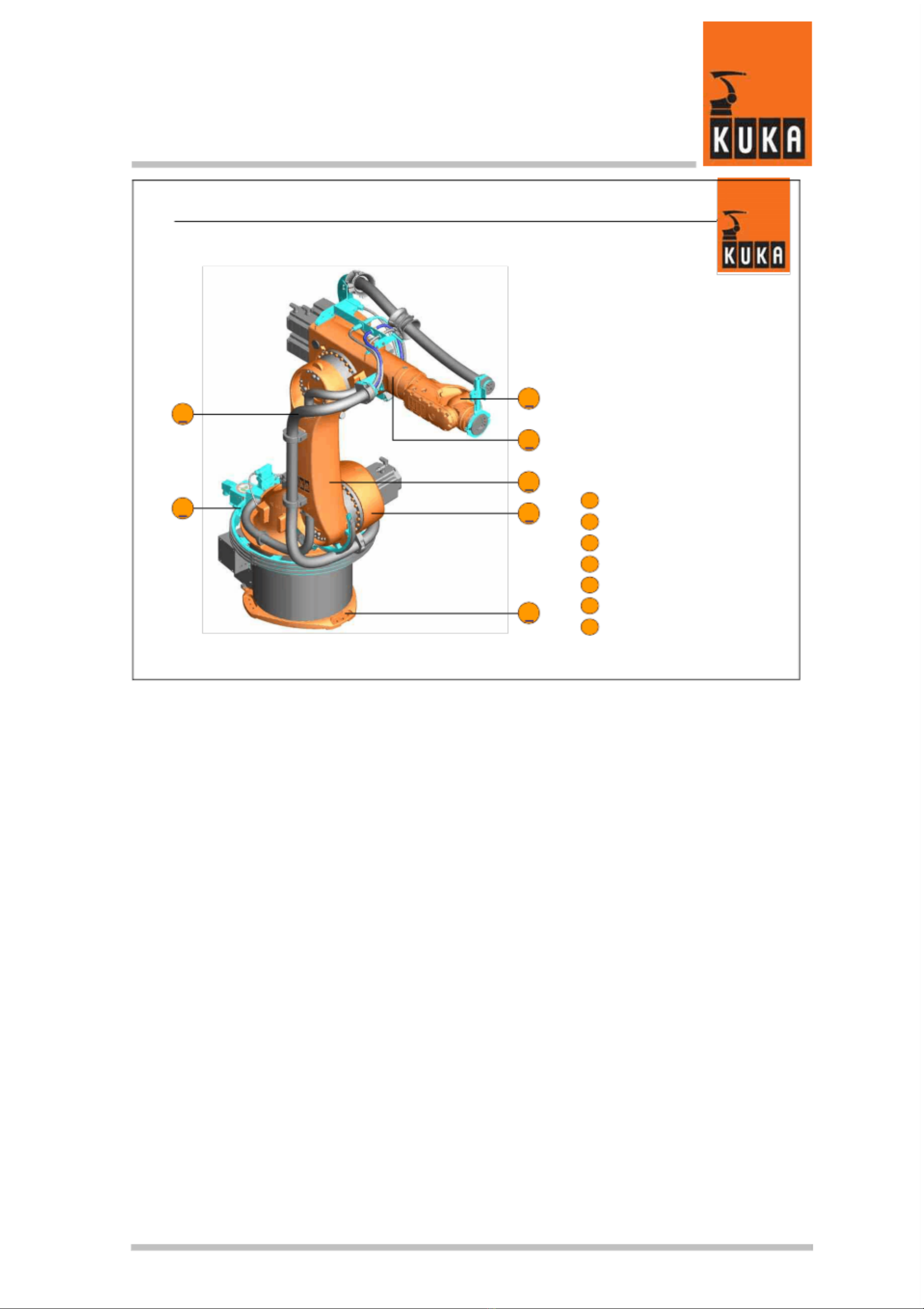
1. Overview Robot............................................................................. 5
2. Disassembly .................................................................................. 9
2.1. Wrist ....................................................................................... 9
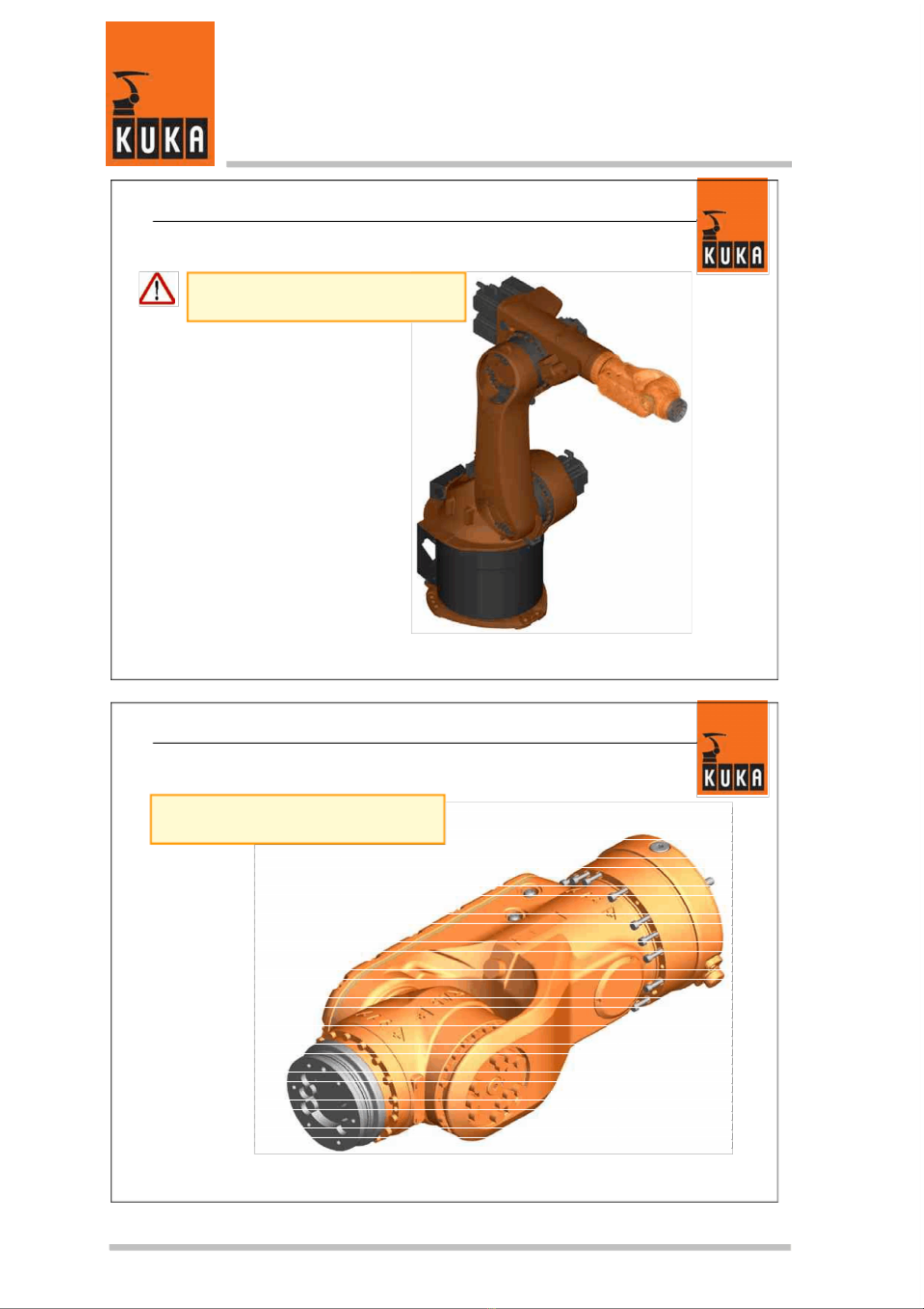
2.2. Arm....................................................................................... 13
2.3. Link arm ............................................................................... 21
2.4. Rotating column ................................................................... 27
2.5. Base unit .............................................................................. 35
2.6. Energy supply ...................................................................... 37
2.7. Axis monitoring..................................................................... 51
3. Assembly..................................................................................... 55
3.1. Base unit .............................................................................. 55
3.2. Rotating column ................................................................... 57
3.3. Link arm ............................................................................... 63
3.4. Arm....................................................................................... 69
3.5. Wrist ..................................................................................... 75
3.6. Energy supply ...................................................................... 81
3.7. Axis monitoring..................................................................... 95
4. Maintenance................................................................................ 99
4.1. Wrist axes ............................................................................ 99
4.2. Basic axes..........................................................................109
5. Exercises...................................................................................113
6. Tightening torques table............................................................139


Overview Robot
? KUKA Roboter GmbH 2005 / SM KR30-3 09.05.00 en Page 5 of 140
1. Overview Robot

Overview Robot
Page 6 of 140 ? KUKA Roboter GmbH 2005 / SM KR30-3 09.05.00 en

Overview Robot
? KUKA Roboter GmbH 2005 / SM KR30-3 09.05.00 en Page 7 of 140
I 25.10.2005 I College I MW I 1
KUKA Roboter G mbH, Hery- Park 300 0,D -86368 G ersthofen, T el.: +49 ( 0) 8 21/45 33-1906, Fax: +49 (0) 8 21/45 33-2340, http://ww w.kuka-r oboter.de
? C opyright by K UKA Roboter GmbH Coll ege
Mechanical servicing, KR 30-3
Energy supply system
Axis range monitoring
Wrist
Arm
Link arm
Rotating column
Base frame
4
3
2
1
5
6
7
1
2
3
4
5
6
7


Disassembly
? KUKA Roboter GmbH 2005 / SM KR30-3 09.05.00 en Page 9 of 140
2. Disassembly
2.1. Wrist

Disassembly
Page 10 of 140 ? KUKA Roboter GmbH 2005 / SM KR30-3 09.05.00 en
I 25 .10.2005 I Col lege I MW I 1
KUKA Roboter GmbH, Hery-Park 3000, D-86368 Gersthofen, Tel.: +49 (0) 8 21/45 33-1906, Fax : +49 (0) 8 21/45 33- 2340, http://www.kuka-rob oter.de
? Copyright by KUKA Roboter G mbH College
Wrist disassembly
Use the appropriate equipment to
ensure that the wrist does not fall!
I 25 .10.2005 I Col lege I MW I 2
KUKA Roboter GmbH, Her y-Park 3000, D-86368 Gersthofen, Tel.: +49 (0) 8 21/45 33-1906, Fax : +49 (0) 8 21/45 33- 2340, http://www.kuka-rob oter.de
? Copyright by KUKA Roboter G mbH College
Loosen and remove sixteen wrist
fastening screws (M6 x 100 / 12.9).
Wrist disassembly

Disassembly
? KUKA Roboter GmbH 2005 / SM KR30-3 09.05.00 en Page 11 of 140
I 25.10.2005 I Coll ege I MW I 3
KUKA Roboter G mbH, Hery- Park 300 0,D -86368 G ersthofen, T el.: +49 ( 0) 8 21/45 33-1906, Fax: +49 (0) 8 21/45 33-2340, http://ww w.kuka-r oboter.de
? C opyright by K UKA Roboter GmbH Coll ege
Wrist disassembly
The wrist must not be tilted as it
is being removed!
Mind the contact surface of the
wrist on the arm and also the
wrist drive shaft.
I 25.10.2005 I Coll ege I MW I 4
KUKA Roboter G mbH, Hery- Park 300 0,D -86368 G ersthofen, T el.: +49 ( 0) 8 21/45 33-1906, Fax: +49 (0) 8 21/45 33-2340, http://ww w.kuka-r oboter.de
? C opyright by K UKA Roboter GmbH Coll ege
Remove the wrist horizontally in the
direction of the arrow and place it on
a suitable support.
Wrist disassembly
2 3
1
16 fastening screws M6 x 100 / 12.9
Wrist
Arm
2
1
3

Disassembly
Page 12 of 140 ? KUKA Roboter GmbH 2005 / SM KR30-3 09.05.00 en
I 25 .10.2005 I Col lege I MW I 5
KUKA Roboter GmbH, Her y-Park 3000, D-86368 Gersthofen, Tel.: +49 (0) 8 21/45 33-1906, Fax : +49 (0) 8 21/45 33- 2340, http://www.kuka-rob oter.de
? Copyright by KUKA Roboter G mbH College
If an arm extension is installed
additional fastening screws (2) need
to be removed.
2 31
Arm extension
16 fastening screws M6 x 35 / 10.9
Arm
2
1
3
Wrist disassembly
Arm extension
I 25 .10.2005 I Col lege I MW I 6
KUKA Roboter GmbH, Her y-Park 3000, D-86368 Gersthofen, Tel.: +49 (0) 8 21/45 33-1906, Fax : +49 (0) 8 21/45 33- 2340, http://www.kuka-rob oter.de
? Copyright by KUKA Roboter G mbH College
Remove the extension section
horizontally in the direction of the arrow
and place it on a suitable support.
Arm extension
21 3
16 fastening screws M6 x 35 / 10.9
Arm extension
Arm
2
1
3
Wrist disassembly

Disassembly
? KUKA Roboter GmbH 2005 / SM KR30-3 09.05.00 en Page 13 of 140
2.2. Arm

Disassembly
Page 14 of 140 ? KUKA Roboter GmbH 2005 / SM KR30-3 09.05.00 en
I 25 .10.2005 I Col lege I MW I 1
KUKA Roboter GmbH, Her y-Park 3000, D-86368 Gersthofen, Tel.: +49 (0) 8 21/45 33-1906, Fax : +49 (0) 8 21/45 33- 2340, http://www.kuka-rob oter.de
? Copyright by KUKA Roboter G mbH College
Arm disassembly
Use the appropriate equipment to
ensure that the arm does not fall!
Unplug the motor and control connectors.
I 25 .10.2005 I Col lege I MW I 2
KUKA Roboter GmbH, Her y-Park 3000, D-86368 Gersthofen, Tel.: +49 (0) 8 21/45 33-1906, Fax : +49 (0) 8 21/45 33- 2340, http://www.kuka-rob oter.de
? Copyright by KUKA Roboter G mbH College
Arm disassembly
Wrist axis motors, axis 4 to axis 6
Remove the three plugs on both
sides of the arm and under the motor
of axis 4.

Disassembly
? KUKA Roboter GmbH 2005 / SM KR30-3 09.05.00 en Page 15 of 140
I 25.10.2005 I Coll ege I MW I 3
KUKA Roboter G mbH, Hery- Park 300 0,D -86368 G ersthofen, T el.: +49 ( 0) 8 21/45 33-1906, Fax: +49 (0) 8 21/45 33-2340, http://ww w.kuka-r oboter.de
? C opyright by K UKA Roboter GmbH Coll ege
3
2
4
1
1
Arm disassembly
Wrist axis motors, axis 4 to axis 6
Unscrew adjusting screws (1) by
several turns, remove fastening
screws (2) and remove motors.
Wrist axis motor A 4
Wrist axis motor A 54
3Adjusting screws
8 motor fastening screws M6 x 25 / 8.82
1
I 25.10.2005 I Coll ege I MW I 4
KUKA Roboter G mbH, Hery- Park 300 0,D -86368 G ersthofen, T el.: +49 ( 0) 8 21/45 33-1906, Fax: +49 (0) 8 21/45 33-2340, http://ww w.kuka-r oboter.de
? C opyright by K UKA Roboter GmbH Coll ege
Arm disassembly
Wrist axis motors, axis 4 to axis 6
When removing the motors their
respective toothed belts in the arm
must be taken off at the same time.
2
1
Toothed belt, wrist axis motor A 4
Toothed belt, wrist axis motor A 52
1

Disassembly
Page 16 of 140 ? KUKA Roboter GmbH 2005 / SM KR30-3 09.05.00 en
I 25 .10.2005 I Col lege I MW I 5
KUKA Roboter GmbH, Her y-Park 3000, D-86368 Gersthofen, Tel.: +49 (0) 8 21/45 33-1906, Fax : +49 (0) 8 21/45 33- 2340, http://www.kuka-rob oter.de
? Copyright by KUKA Roboter G mbH College
Arm disassembly
Wrist axis motors, axis 4 to axis 6
Remove fastening screws (2) on the
axis 6 motor (1) and take the motor
out
1 2
W rist axis motor A 6
4 motor fastening screws M8 x 18 / 8.82
1
Attention must be paid to any
loose disc springs!
I 25 .10.2005 I Col lege I MW I 6
KUKA Roboter GmbH, Her y-Park 3000, D-86368 Gersthofen, Tel.: +49 (0) 8 21/45 33-1906, Fax : +49 (0) 8 21/45 33- 2340, http://www.kuka-rob oter.de
? Copyright by KUKA Roboter G mbH College
Arm disassembly
Motor A 3
Unscrew fastening screws (3) and
remove motor (2).
Secure the arm so that it cannot
move!
Arm
Motor A 3
4 motor fastening screws M12 x 30 / 8.8
2
1
3
1 2 3

Disassembly
? KUKA Roboter GmbH 2005 / SM KR30-3 09.05.00 en Page 17 of 140
I 25.10.2005 I Coll ege I MW I 7
KUKA Roboter G mbH, Hery- Park 300 0,D -86368 G ersthofen, T el.: +49 ( 0) 8 21/45 33-1906, Fax: +49 (0) 8 21/45 33-2340, http://ww w.kuka-r oboter.de
? C opyright by K UKA Roboter GmbH Coll ege
Arm disassembly
Loosen and remove fastening screws (2).
1
2
Arm
6 fastening screws M16 x 100 / 10.9
1
2
I 25.10.2005 I Coll ege I MW I 8
KUKA Roboter G mbH, Hery- Park 300 0,D -86368 G ersthofen, T el.: +49 ( 0) 8 21/45 33-1906, Fax: +49 (0) 8 21/45 33-2340, http://ww w.kuka-r oboter.de
? C opyright by K UKA Roboter GmbH Coll ege
Arm disassembly
Loosen and remove fastening screws (2).
Arm
18 fastening screws M10 x 90 / 10.9
1
2
1
2

Disassembly
Page 18 of 140 ? KUKA Roboter GmbH 2005 / SM KR30-3 09.05.00 en
I 25 .10.2005 I Col lege I MW I 9
KUKA Roboter GmbH, Her y-Park 3000, D-86368 Gersthofen, Tel.: +49 (0) 8 21/45 33-1906, Fax : +49 (0) 8 21/45 33- 2340, http://www.kuka-rob oter.de
? Copyright by KUKA Roboter G mbH College
Arm disassembly
Take off support ring (3).
6 fastening screws M16 x 100 / 10.9
18 fastening screws M10 x 90 / 10.9
Support ring
2
1
3
1 2 3
I 25 .10.2005 I Col lege I MW I 10
KUKA Roboter GmbH, Her y-Park 3000, D-86368 Gersthofen, Tel.: +49 (0) 8 21/45 33-1906, Fax : +49 (0) 8 21/45 33- 2340, http://www.kuka-rob oter.de
? Copyright by KUKA Roboter G mbH College
Arm disassembly
Push the arm out of its location and
carefully swing it away.
The arm must not be tilted while
it is being lifted off.

Disassembly
? KUKA Roboter GmbH 2005 / SM KR30-3 09.05.00 en Page 19 of 140
I 25.10.2005 I Coll ege I MW I 11
KUKA Roboter G mbH, Hery- Park 300 0,D -86368 G ersthofen, T el.: +49 ( 0) 8 21/45 33-1906, Fax: +49 (0) 8 21/45 33-2340, http://ww w.kuka-r oboter.de
? C opyright by K UKA Roboter GmbH Coll ege
Arm disassembly
Grease the toothing of the shafts
with Microlube GL261.
Motor A 6
Motor A 6
Ring
Disc springs
2
1
3
1
2
3

This manual suits for next models
3
Table of contents
Other Kuka Robotics manuals

Kuka
Kuka IONTEC KR 20 R3100 User manual

Kuka
Kuka KR 30-2 User manual

Kuka
Kuka KRC4 User manual

Kuka
Kuka Pulse Installation guide

Kuka
Kuka KR 30 HA User manual

Kuka
Kuka iiQKA LBR iisy User manual

Kuka
Kuka KUKA.EthernetKRL 2.2 User manual

Kuka
Kuka LBR iisy User manual

Kuka
Kuka VisionTech 2.1 User manual

Kuka
Kuka ready2 educate User manual