manuals.online logo
Brands
  1. Home
  2. •
  3. Brands
  4. •
  5. turck
  6. •
  7. Control Unit
  8. •
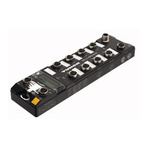
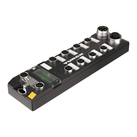
  9. turck TBEN-LL-8IOL User manual

turck TBEN-LL-8IOL User manual

Your Global Automation Partner
Instructions for Use
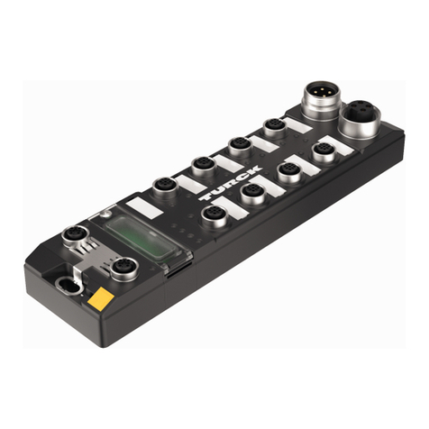
TBEN-LL-8IOL
IO-Link Master Module
2Hans Turck GmbH & Co. KG | T +49 208 4952-0 | F +49 208 4952-264 | [email protected] | www.turck.com
V01.00 | 2019/11 3
Table of Contents
1 About These Instructions.................................................................................................................. 7
1.1 Target groups................................................................................................................... 7
1.2 Explanation of symbols used ........................................................................................ 7
1.3 Additional documents.................................................................................................... 7
1.4 Feedback about these instructions.............................................................................. 7
2 Notes on the Product......................................................................................................................... 8
2.1 Product identification..................................................................................................... 8
2.2 Scope of delivery ............................................................................................................. 8
2.3 Legal requirements.........................................................................................................8
2.4 Manufacturer and service.............................................................................................. 8
3 For Your Safety.................................................................................................................................... 9
3.1 Intended use..................................................................................................................... 9
3.2 General safety notes ....................................................................................................... 9
4 System Description IO-Link ............................................................................................................10
4.1 Features...........................................................................................................................10
4.2 System architecture ......................................................................................................11
4.3 Operating principle.......................................................................................................12
4.4 Operating modes...........................................................................................................12
4.4.1 IO-Link mode...................................................................................................................................12
4.4.2 Standard I/O mode (SIO mode) ................................................................................................14
5 Product Description .........................................................................................................................15
5.1 Device overview ............................................................................................................15
5.1.1 Block diagram..................................................................................................................................16
5.2 Properties and features................................................................................................16
5.3 Operating principle.......................................................................................................17
5.4 Functions and operating modes ................................................................................17
5.4.1 Multiprotocol technology...........................................................................................................17
5.4.2 IO-Link channels.............................................................................................................................17
5.4.3 Configurable digital channels – functions............................................................................18
6 Mounting............................................................................................................................................19
6.1 Mounting the device outdoors...................................................................................19
6.2 Grounding the device...................................................................................................20
6.2.1 Equivalent wiring diagram and shielding concept ...........................................................20
6.2.2 Shielding of the fieldbus and I/O level...................................................................................20
6.2.3 Grounding the device – I/O level and fieldbus level.........................................................21
7 Connecting ........................................................................................................................................23
7.1 Connecting the device to Ethernet............................................................................23
7.2 Connecting the power supply ....................................................................................24
7.2.1 Supply concept...............................................................................................................................25
7.3 Connecting IO-Link devices and digital sensors .....................................................26
8 Commissioning .................................................................................................................................28
8.1 Setting the IP address...................................................................................................28
8.1.1 Setting the IP address via switches at the device...............................................................28
8.1.2 Setting the IP address with Turck Service Tool ...................................................................30
Table of Contents
4Hans Turck GmbH & Co. KG | T +49 208 4952-0 | F +49 208 4952-264 | [email protected] | www.turck.com
8.1.3 Setting the IP address via the web server .............................................................................32
8.2 ARGEE/FLC ......................................................................................................................33
8.3 Commissioning an IO-Link device with IO-Link V1.0..............................................33
8.4 Commissioning an IO-Link device with IO-Link V1.1..............................................34
8.5 Read in connected IO-Link devices: topology scan in the DTM ...........................36
8.6 Commissioning the device in PROFINET...................................................................37
8.6.1 PROFINET IO device model.........................................................................................................37
8.6.2 Device model – TBEN-L…-8IOL ................................................................................................38
8.6.3 Address setting in PROFINET .....................................................................................................39
8.6.4 FSU – Fast Start-Up (prioritized startup)................................................................................39
8.6.5 MRP (Media Redundancy Protocol).........................................................................................39
8.6.6 User data for acyclic services .....................................................................................................40
8.6.7 The IO-Link function block IOL_CALL.....................................................................................44
8.7 Connecting the device to a Siemens PLC in PROFINET..........................................48
8.7.1 Installing the GSDML file.............................................................................................................49
8.7.2 Connecting the devices to the PLC .........................................................................................50
8.7.3 Assigning the PROFINET device name...................................................................................51
8.7.4 Setting the IP address in TIA Portal .........................................................................................52
8.7.5 Configuring device functions....................................................................................................53
8.7.6 Going online with the PLC..........................................................................................................56
8.7.7 PROFINET – mapping ...................................................................................................................56
8.7.8 Use the IO_LINK_DEVICE function block in TIA Portal......................................................57
8.8 Commissioning the device in Modbus TCP..............................................................64
8.8.1 Implemented Modbus functions .............................................................................................64
8.8.2 Modbus registers ...........................................................................................................................64
8.8.3 Data width........................................................................................................................................67
8.8.4 Register mapping...........................................................................................................................68
8.8.5 Error Behavior (watchdog)..........................................................................................................70
8.9 Commissioning the Device in EtherNet/IP ...............................................................70
8.9.1 Common EtherNet/IP features..................................................................................................70
8.9.2 EDS files and catalog files............................................................................................................70
8.9.3 Device Level Ring (DLR)...............................................................................................................71
8.9.4 Diagnostic messages via process data...................................................................................71
8.9.5 EtherNet/IP standard classes .....................................................................................................72
8.9.6 VSC-Vendor Specific Classes ......................................................................................................92
8.10 Connecting the Devices to a Rockwell PLC with EtherNet/IP ............................ 106
8.10.1 Adding the devices from the catalog files to the new project................................... 107
8.10.2 Configuring the device in RS Logix ...................................................................................... 109
8.10.3 Parameterizing the device....................................................................................................... 110
8.10.4 Going online with the PLC....................................................................................................... 111
8.10.5 Reading process data ................................................................................................................ 113
9 Parameterizing and Configuring.................................................................................................114
9.1 Parameters................................................................................................................... 114
9.1.1 Adapting process data mapping........................................................................................... 120
9.1.2 PROFINET parameters ............................................................................................................... 121
9.2 IO-Link functions for acyclic communication ....................................................... 121
9.2.1 Port functions for Port 0 (IO-Link Master)........................................................................... 122
10 Operating .........................................................................................................................................127
10.1 Process input data...................................................................................................... 127
10.2 Process output data................................................................................................... 129
10.3 LED displays................................................................................................................. 130
V01.00 | 2019/11 5
10.4 Software diagnostic messages ................................................................................ 131
10.4.1 Status- and control word.......................................................................................................... 132
10.4.2 Diagnostic telegram................................................................................................................... 133
10.4.3 PROFINET diagnostics ............................................................................................................... 135
10.5 Using the data storage mode................................................................................... 137
10.5.1 Parameter ”data storage mode” = activated .................................................................... 137
10.5.2 Parameter ”data storage mode” = read in ......................................................................... 139
10.5.3 Parameter ”data storage mode” = overwrite.................................................................... 139
10.5.4 Parameter ”data storage mode” = deactivated, clear.................................................... 139
11 Troubleshooting .............................................................................................................................140
11.1 Eliminate parameterization errors.......................................................................... 140
12 Maintenance....................................................................................................................................141
12.1 Carry out firmware update via FDT/DTM............................................................... 141
13 Repair................................................................................................................................................144
13.1 Returning devices....................................................................................................... 144
14 Disposal ............................................................................................................................................144
15 Technical data .................................................................................................................................145
Table of Contents
6Hans Turck GmbH & Co. KG | T +49 208 4952-0 | F +49 208 4952-264 | [email protected] | www.turck.com
V01.00 | 2019/11 7
1 About These Instructions
These operating instructions describe the structure, functions and the use of the product and
will help you to operate the product as intended. Read these instructions carefully before using
the product. This is to avoid possible damage to persons, property or the device. Retain the in-
structions for future use during the service life of the product. If the product is passed on, pass
on these instructions as well.
1.1 Target groups
These instructions are aimed at qualified personal and must be carefully read by anyone
mounting, commissioning, operating, maintaining, dismantling or disposing of the device.
1.2 Explanation of symbols used
The following symbols are used in these instructions:
DANGER
DANGER indicates a dangerous situation with high risk of death or severe injury if
not avoided.
WARNING
WARNING indicates a dangerous situation with medium risk of death or severe in-
jury if not avoided.
CAUTION
CAUTION indicates a dangerous situation of medium risk which may result in minor
or moderate injury if not avoided.
NOTICE
NOTICE indicates a situation which may lead to property damage if not avoided.
NOTE
NOTE indicates tips, recommendations and useful information on specific actions
and facts. The notes simplify your work and help you to avoid additional work.
uCALL TO ACTION
This symbol denotes actions that the user must carry out.
aRESULTS OF ACTION
This symbol denotes relevant results of actions.
1.3 Additional documents
The following additional documents are available online at www.turck.com:
nData sheet
nEU Declaration of Conformity
nCommissioning manual IO-Link devices
1.4 Feedback about these instructions
We make every effort to ensure that these instructions are as informative and as clear as pos-
sible. If you have any suggestions for improving the design or if some information is missing in
the document, please send your suggestions to [email protected].
Notes on the Product
Manufacturer and service
8Hans Turck GmbH & Co. KG | T +49 208 4952-0 | F +49 208 4952-264 | [email protected] | www.turck.com
2 Notes on the Product
2.1 Product identification
These instructions apply for the following IO-Link master module:
nTBEN-LL-8IOL
2.2 Scope of delivery
The scope of delivery includes:
nTBEN-LL-8IOL
nClosure caps for M12 female connectors
nLabel clips
2.3 Legal requirements
The device falls under the following EU directives:
n2014/30/EU (electromagnetic compatibility)
n2011/65/EU (RoHS Directive)
2.4 Manufacturer and service
Hans Turck GmbH & Co. KG
Witzlebenstraße 7
45472 Mülheim an der Ruhr
Germany
Turck supports you with your projects, from initial analysis to the commissioning of your applic-
ation. The Turck product database contains software tools for programming, configuration or
commissioning, data sheets and CAD files in numerous export formats. You can access the
product database at the following address: www.turck.de/products
For further inquiries in Germany contact the Sales and Service Team on:
nSales: +49 208 4952-380
nTechnology: +49 208 4952-390
Outside Germany, please contact your local Turck representative.
V01.00 | 2019/11 9
3 For Your Safety
The product is designed according to state-of-the-art technology. However, residual risks still
exist. Observe the following warnings and safety notices to prevent damage to persons and
property. Turck accepts no liability for damage caused by failure to observe these warning and
safety notices.
3.1 Intended use
These devices are designed solely for use in industrial areas.
The multiprotocol I/O module TBEN-LL-8IOL is an IO-Link master according to IO-Link specifica-
tion V1.1 and can be can be operated in the three Ethernet protocols PROFINET, Ethernet/IP
and Modbus TCP. The module detects the bus protocol automatically during the start-up.
The IO-Link master module TBEN-LL-8IOL has eight IO-Link channels. Up to eight IO-Link
sensors or IO hubs with IO-Link can be connected to the M12 sockets. In addition, up to 12 di-
gital sensors can be connected directly it. When using I/O hubs, it is possible to connect up to
128 digital sensors per device.
The devices may only be used as described in these instructions. Any other use is not in accord-
ance with the intended use. Turck accepts no liability for any resulting damage.
3.2 General safety notes
nThe device may only be assembled, installed, operated, parameterized and maintained by
professionally-trained personnel.
nThe device may only be used in accordance with applicable national and international regu-
lations, standards and laws.
nThe device only meets the EMC requirements for industrial areas and is not suitable for use
in residential areas.
nChange the default password of the integrated web server after the first login. Turck recom-
mends using a secure password.
System Description IO-Link
Features
10 Hans Turck GmbH & Co. KG | T +49 208 4952-0 | F +49 208 4952-264 | [email protected] | www.turck.com
4 System Description IO-Link
IO-Link is a fieldbus independent communication interface for sensors and actuators. Signals
and energy can be exchanged between any networks, fieldbuses and backplane buses via a di-
gital, serial point-to-point connection.
Each IO-Link system consists of an IO-Link master and an IO-Link device (e.g. sensor, I/O hub,
valve block). An IO-Link master is provided with at least one IO-Link port (channel). One IO-Link
device can be connected to each port. The system components are interconnected according
to the port specification via unshielded 3-wire or 5-wire standard cables.
The IO-Link technology is described in the “IO-Link Interface and System Specification” and
IEC61131-9. IO-Link capable devices comply either with specification V1.0 or specification V1.1.
The properties, functions and parameters of the IO-Link device are represented in an electronic
device description (IODD). The IODDs for Turck devices can be downloaded via the Turck Soft-
ware Manager and can also be obtained free of charge from www.turck.com . The IODDs of all
devices have the same structure and contain the following information for system integration
nCommunication properties
nDevice parameters with value range and default value
nIdentification, process and diagnostic data
nDevice data
nText description
nPicture of the device
nLogo of the manufacturer
The structure of the IODD is defined by the IO-Link specification and is the same for all IO-Link
devices. The IODD is based on indexes. The communication properties, device parameters,
identification, process, diagnostic and device data are assigned to fixed indexes in the IODD, via
which the parameters can be controlled. Some indexes are further divided by sub indexes.
4.1 Features
nPoint-to-point connection (max. cable length: 20 m)
nUnshielded 3-wire or 5-wire standard cables
nCyclical process data transmission
nAcyclical data transmission, e.g. device data and events
nCommunication between IO-Link master and IO-Link device possible in three transmission
rates
nParallel exchange of device data without influencing the process data
nCommunication via 24 V pulse modulation, standard UART protocol
V01.00 | 2019/11 11
4.2 System architecture
At least one IO-Link master and one IO-Link device (e.g. sensor or actuator) are required for IO-
Link communication. IO-Link master and IO-Link device are interconnected via an unshielded 3-
wire or 5-wire standard cable. The setting can be carried out with a configuration tool or via the
fieldbus level.
The IO-Link master establishes the connection between IO-Link device and the higher-level
control system. An IO-Link master can have several IO-Link ports. Only one IO-Link device can
be connected to each port.
IO-Link hubs also make it possible to integrate devices without an IO-Link output in automation
systems via IO-Link.
Standard tools and functions are provided for the integration, commissioning and configura-
tion of the IO-Link communication.
BL67-B-4M8
0
2
1
0
3
2
BL67-B-4M12-P
0
1
2
3
4
5
6
7
0
Power
BL67-B-1RSM
D
BL67 D
BL67 D
BL67
BL67-B-8M8
D
BL67
1
3
D
BL67
D
BL67
1 1 1 1 1
0
2
4
6
3
5
7
0 0
2
0
2
4
6
3
5
7
0
2
3
5
4
7
6
BL67-B-2M12
0
1
2
3
Fig.1: IO-Link system overview
System Description IO-Link
Operating modes
12 Hans Turck GmbH & Co. KG | T +49 208 4952-0 | F +49 208 4952-264 | [email protected] | www.turck.com
4.3 Operating principle
IO-Link is a digital point-to-point connection between an IO-Link master and an IO-Link device.
Process data and other information such as parameters and diagnostic messages are trans-
ferred with a 24 V pulse modulation via a combined switching status and data channel (C/Q).
IO-Link communication is independent of the fieldbus used.
4.4 Operating modes
The operating mode can be set separately at any port of the IO-Link master.
Two operating modes are available for the IO-Link master:
nIO-Link mode: IO-Link communication possible
nStandard I/O mode (SIO): digital I/O communication
IO-Link communication is implemented via the switching and communication cable (C/Q).
2
1
3
L+
C/Q
L–
4
5
IO-Link
SIO
Fig.2: IO-Link communication via C/Q
During initialization the ports of the IO-Link master behave like a normal digital input. The IO-
Link devices are operated in IO-Link mode. A command of the higher-level IO-Link master es-
tablishes IO-Link communication in IO-Link mode. This command is called the “Wake-up re-
quest”.
4.4.1 IO-Link mode
In IO-Link mode communication takes place between an IO-Link master and an IO-Link device.
Communication always starts from the IO-Link master.
Transmission speed between IO-Link master and IO-Link device
Three transmission rates are defined in the IO-Link specification:
n4,8 kBaud
n38,4 kBaud
n230,4 kBaud
Each device supports only one transmission rate, an IO-Link master supports all transmission
rates. The transfer time of the cyclical process data is determined by the telegram length as well
as the delay times in the device and the master. With a transmission rate of 38.4 kBaud and a
telegram length of 2 byte the transmission time is typically 2.3 ms.
Response times
The response time of the IO-Link system provides information on the frequency and speed of
the data transmission between IO-Link master and IO-Link device. This response time depends
on the following factors:
nMinimum cycle time: Intervals defined in the IODD in which the IO-Link master addresses the
IO-Link device. Different minimum cycle times can be defined for different devices.
nInternal processing time of the IO-Link master and the IO-Link device
V01.00 | 2019/11 13
Cyclical and Acyclical Communication
The data exchanged between IO-Link master and the IO-Link device can be divided into cyclical
process data and acyclical data. Process data and value states are transferred cyclically. Acyc-
lical data is transferred separately to cyclic process data. Acyclical data includes device data,
parameter functions and events such as diagnostic information, which is only transferred on re-
quest. The two communication types are independent of each other and do not interact.
Cyclical communication
Process data Value status (port qualifier)
n0…32 bytes of process data possible per
device (each input and output)
nProcess data size determined by the device
nThe Port Qualifier indicates whether the
process data is valid or not.
Acylical communication
Device data Value status (port qualifier)
nParameters, identification data or
diagnostic information
nData exchange on request of the IO-Link
master
nDevice data can be written to the device or
read from the device.
nDevice indicates event to master: Error mes-
sages and warnings
nMaster indicates event to device: e.g. cable
break or communication abort
Combining IO-Link devices with different specifications
Only devices of specification V1.0 can be operated on IO-Link masters of specification V1.0.
Devices of specification V1.0 and V1.1 can be operated on IO-Link masters of specification V1.1.
IO-Link device V1.0 IO-Link device V1.1
IO-Link master V1.0 x -
IO-Link master V1.1 x x
System Description IO-Link
Operating modes
14 Hans Turck GmbH & Co. KG | T +49 208 4952-0 | F +49 208 4952-264 | [email protected] | www.turck.com
Data storage mode
NOTE
Data storage mode is only available for devices complying with the IO-Link specifica-
tion V1.1.
Data storage mode makes it possible to replace IO-Link devices without the need for a reconfig-
uration.
The IO-Link master or the IO-Link device save the device parameters set in the previous config-
uration. In data storage mode the parameter data memories of IO-Link master and IO-Link
device are synchronized. If data storage mode is activated in the IO-Link master, the master
writes the stored device parameters to the new device after a device is replaced. The applica-
tion can be restarted without having to perform a new configuration.
IO-Link-Master
(IOLM)
IO-Link-Device
(IOLD)
DS_UPLOAD_FLAG
Fig.3: Data storage mode – general principle, Para. IOLD = parameters of the IO-Link device
4.4.2 Standard I/O mode (SIO mode)
In standard I/O mode IO-Link devices behave like digital sensors or actuators. In this mode the
devices only send input or output data to the higher-level instance. IO-Link access to the device
is not possible.
V01.00 | 2019/11 15
5 Product Description
The devices are designed in a fully encapsulated housing with degree of protection IP65/IP67/
IP69K.
The IO-Link master module TBEN-LL-8IOL has eight IO-Link ports for connecting IO-Link
devices. The IO-Link ports at the connectors X0…X3 are designed as Class A ports. The IO-Link
ports at the connectors X4…X7 are designed as Class B ports. In addition to the four IO-Link-
channels, four universal digital DXP channels (PNP) are available. The eight IO-Link channels
can be parameterized independently of each other and operated either in IO-Link mode or in
SIO mode
(DI).
With Turck's "Simple IO-Link Device Integration (SIDI)", IO-Link devices can be directly integ-
rated into PROFINET via the GSDML file of the TBEN-LL-8IOL.
The 4 universal digital channels are designed as DXP-channels and can therefore be parameter-
ized as in- or output.
For connecting the supply voltage, the device has 5-pin M12 connectors.
The multiprotocol device can be operated with the three Ethernet protocols PROFINET, Ethern-
Net/IP and Modbus TCP mentioned above by automatic protocol detection without user inter-
vention
5.1 Device overview
34.8 [1.37]
Ø 6.3 [0.25]
217.9 [8.58]
230.4 [9.07]
6 [0.24]
60.4 [2.38]
Ø 6.4 [0.25]
30.2 [1.19]
24 [0.95]
X7XF2 X6 X5 X4
X3XF1 X2 X1 X0
XD2
XD1
Fig.4: Dimensions TBEN-LL-8IOL
Product Description
Properties and features
16 Hans Turck GmbH & Co. KG | T +49 208 4952-0 | F +49 208 4952-264 | [email protected] | www.turck.com
5.1.1 Block diagram
IN Diag
IO-Link Diag
IO-Link Data
1 VAUX1 (V1)
2 IN/OUT (V1)
4 C/Q (V1)
OUT Diag
3 GND (V1)
In/OutputClass A
I/O
IO-Link
µC
5 n.c.
V1 +
IO-Link
IN Diag
IO-Link Diag
IO-Link Data
1 VAUX1 (V1)
2 VAUX2 (V2)
4 C/Q (V1)
OUT Diag
3 GND (V1)
5 GND (V2)
In/OutputClass B
I/O
IO-Link
µC
V2 +
V1 +
IO-Link
ERR
BUS
PWR
µC
Supply
µC
V1
4
2
1
+
V1
2
3
3
–
V2
5
1
4
+
V2
1
4
2
–
FE
3
FE
FE
3
FE
V1
4
2
1
+
V1
2
3
3
–
V2
5
1
4
+
V2
1
4
2
–
X1 X2
IN Diag
OUT Diag
IO-Link Data
V1 Diag V2 Diag
IO-Link Diag
Ethernet
V1 +
V2 +
P2P1
4
13
2
4
13
2
ETH2ETH1
Ethernet
… TBEN-L5
… TBEN-L4
… TBEN-LL
Fig.5: Block diagram
5.2 Properties and features
nFibre-glass reinforced housing
nShock and vibration tested
nFully potted module electronics
nDegree of protection IP67/IP69K
nUV-resistant according to DIN EN ISO 4892-2
nMetal connectors
n4 IO-Link ports Class A and 4 IO-Link ports Class B
nMultiprotocol functionality: PROFINET Device, EtherNet/IP Device, Modbus TCP Slave
n4 universal DXP channels
nPROFINET:
– Conformance Class B PA
– Simple IO-Link Device Integration (SIDI)
– Conformance according to PROFINET specifikation V2.35
– System redundancy S2
– Network load class 3
nEtherNet/IP:
– Support of the IO-Link Parameter Object for asynchronous services (IO-Link CALL)
– Predefined in- and oputput assemblies
V01.00 | 2019/11 17
5.3 Operating principle
The IO-Link master module TBEN-LL-8IOL connects IO-Link sensors and actuators with the
higher-level control system. The device has an Ethernet interface and fieldbus-independent I/O
electronics with IO-Link master functionality (Class A and Class B ports). Via the Ethernet inter-
face, the IO-Link master is connected to an (existing) Ethernet network as an EtherNet/IP device,
Modbus TCP slave or PROFINET device. During operation, the process data is exchanged
between Ethernet and IO-Link. In addition the devices can process signals from sensors and ac-
tuators via four configurable digital channels.
5.4 Functions and operating modes
5.4.1 Multiprotocol technology
The devices can be used in the following three Ethernet protocols:
nModbus TCP
nEtherNet/IP
nPROFINET
The required Ethernet protocol can be detected automatically or determined manually.
Automatic protocol detection
A multi-protocol device can be operated without intervention of the user (which means,
without changes in the parameterization) in all of the three Ethernet protocols mentioned.
During the system start-up phase (snooping phase), the module detects which Ethernet pro-
tocol requests a connection to be established and adjusts itself to the corresponding protocol.
After this an access to the device from other protocols is read-only.
Manual Protocol Selection
The user can also define the protocol manually. In this case, the snooping phase is skipped and
the device is fixed to the selected protocol. With the other protocols, the device can only be ac-
cessed read-only.
Protocol Dependent Functions
The device Supported the following Ethernet protocol specific functions:
PROFINET
nFSU - Fast Start-Up (prioritized startup)
nTopology discovery
nAddress assignment via LLDP
nMRP (Media Redundancy Protocol)
EtherNet/IP
nQC – QuickConnect
nDevice Level Ring (DLR)
5.4.2 IO-Link channels
The IO-Link master module TBEN-LL-8IOL has four Class A IO-Link ports (slots X0…X3) and four
Class B IO-Link ports (slots X4…X7).
The eight IO-Link channels can be parameterized independently of each other and operated
either in IO-Link mode or in SIO mode (DI).
Product Description
Functions and operating modes
18 Hans Turck GmbH & Co. KG | T +49 208 4952-0 | F +49 208 4952-264 | [email protected] | www.turck.com
Simple IO-Link Device Integration (SIDI)
Turck's Simple IO-Link Device Integration (SIDI) simplifies the handling of IO-Link devices in
PROFINET engineering systems. Since the devices are already integrated in the GSDML file of
the master, the user can select the devices from the device library (for example in the TIA
portal) and integrate them into his project via drop-down fields as if the devices were submod-
ules of a modular I/O system. The user benefits from plain text access to all device properties
and parameters. Measuring ranges, switching points and pulse rates can be set directly from
the engineering system - without programming or additional software.
5.4.3 Configurable digital channels – functions
The device is provided with four digital channels, which can be configured as inputs or outputs
according to the application requirements. In all, up to four 3-wire PNP sensors or four PNP DC
actuators with a maximum output current of 0.5 A can be connected per input or output.
V01.00 | 2019/11 19
6 Mounting
NOTICE
Mounting on uneven surfaces
Device damage due to stresses in the housing
Fix the device on a flat mounting surface.
Use two M6 screws for mounting.
The device can be screwed onto a flat mounting plate.
Attach the module to the mounting surface with two M6 screws. The maximum tighten-
ing torque for the screws is 1.5 Nm.
Avoid mechanical stresses.
Optional: Ground the device.
218 [5.58]
M6 (2x)
max. 1.5 Nm
Fig.6: Mounting the device on a mounting plate
6.1 Mounting the device outdoors
The device is UV-resistant according to DIN EN ISO 4892-2. Direct sunlight can cause material
abrasion and color changes. The mechanical and electrical properties of the device are not af-
fected.
To avoid material abrasion and color changes: Protect the device from direct sunlight,
e.g. by using protective shields.
Mounting
Grounding the device
20 Hans Turck GmbH & Co. KG | T +49 208 4952-0 | F +49 208 4952-264 | [email protected] | www.turck.com
6.2 Grounding the device
6.2.1 Equivalent wiring diagram and shielding concept
1 nF
2,2 MΩ
XD1
X0
X1
X2
X3
XF1
XD2
X4
X5
X6
X7
XF2
4 x 15 nF
Fig.7: TBEN-LL-8IOL equivalent circuit diagram and shielding concept
6.2.2 Shielding of the fieldbus and I/O level
The fieldbus and the I/O level of the modules can be grounded separately.
1
2
3
Fig.8: Grounding clip (1), grounding ring (2) and metal screw (3)
The grounding ring (2) is the module grounding. The shielding of the I/O level is permanently
connected to the module grounding. The module grounding is only connected to the refer-
ence potential of the installation when the module is mounted.
Shielding concept of the I/O modules (I/O level)
In the case of direct mounting on a mounting plate, the module grounding is connected to the
reference potential of the system via the metal screw in the lower mounting hole (3). If module
grounding is not desired, the electrical connection to the reference potential must be interrup-
ted, e.g. by using a plastic screw.

Other turck Control Unit manuals

turck excom I/O System Use and care manual

turck

turck excom I/O System Use and care manual

turck FXDP Series User manual

turck

turck FXDP Series User manual

turck BL67 User manual

turck

turck BL67 User manual

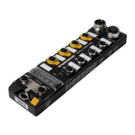
turck TBEN-Lx-8IOL User manual

turck

turck TBEN-Lx-8IOL User manual

turck TBEN-L 8IOL Series User manual

turck

turck TBEN-L 8IOL Series User manual

turck TBEN-S Series User manual

turck

turck TBEN-S Series User manual

turck DF20-N User manual

turck

turck DF20-N User manual

turck TBEN EN1 Series User manual

turck

turck TBEN EN1 Series User manual

turck TX700 HMI/PLC Series User manual

turck

turck TX700 HMI/PLC Series User manual

turck TBEN-S2-4IOL User manual

turck

turck TBEN-S2-4IOL User manual

turck IO-LINK MASTER User manual

turck

turck IO-LINK MASTER User manual

turck TBEN-LH-8IOL User manual

turck

turck TBEN-LH-8IOL User manual

turck TX-EXTEND User manual

turck

turck TX-EXTEND User manual

turck excom-RMD1-BU User manual

turck

turck excom-RMD1-BU User manual

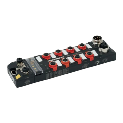
turck TBEC-LL-4RFID-8DXP User manual

turck

turck TBEC-LL-4RFID-8DXP User manual

turck TBEN-RFID Series Technical manual

turck

turck TBEN-RFID Series Technical manual

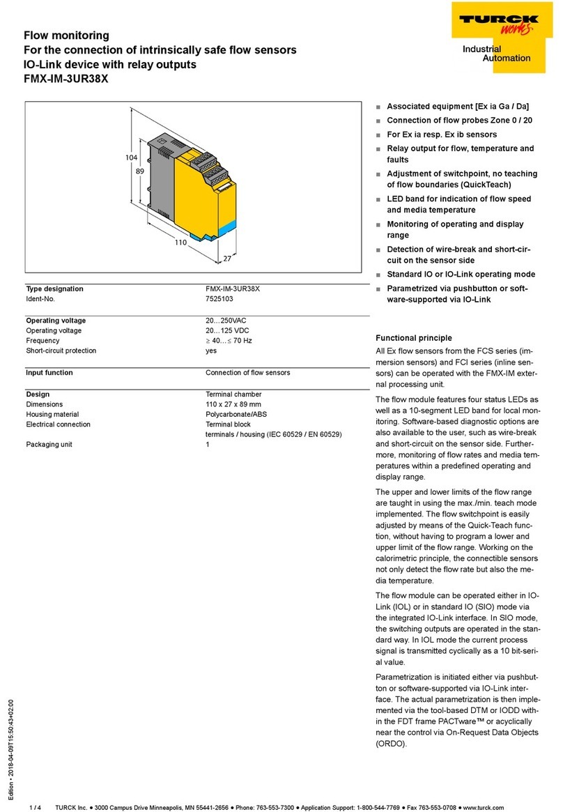
turck FMX-IM-3UR38X User manual

turck

turck FMX-IM-3UR38X User manual

turck FDN-DN1 User manual

turck

turck FDN-DN1 User manual

turck TBIP-L 4FDI-4FDX Series User manual

turck

turck TBIP-L 4FDI-4FDX Series User manual

turck TBPN-L FDIO1-2IOL Series User manual

turck

turck TBPN-L FDIO1-2IOL Series User manual

turck TBPN-L1-FDIO1-2IOL User manual

turck

turck TBPN-L1-FDIO1-2IOL User manual

turck IM18-CCM51-12I User manual

turck

turck IM18-CCM51-12I User manual

Popular Control Unit manuals by other brands

iWave iW-RainboW-G20M Hardware user's guide

iWave

iWave iW-RainboW-G20M Hardware user's guide

A.R.I. D-025 L ARISENSE Installation operation & maintenance

A.R.I.

A.R.I. D-025 L ARISENSE Installation operation & maintenance

END ARMATUREN MGM Series Mounting and operating manual

END ARMATUREN

END ARMATUREN MGM Series Mounting and operating manual

Hopeland CL7206A5 user manual

Hopeland

Hopeland CL7206A5 user manual

PalmSens EmStat3+ Getting started

PalmSens

PalmSens EmStat3+ Getting started

Samson 3248 Mounting and operating instructions

Samson

Samson 3248 Mounting and operating instructions

Kuhse KEA 291 NSTR operating instructions

Kuhse

Kuhse KEA 291 NSTR operating instructions

IBM 8271 Nways Ethernet LAN Switch manual

IBM

IBM 8271 Nways Ethernet LAN Switch manual

HAI Hi-Fi 62A12-1 installation manual

HAI

HAI Hi-Fi 62A12-1 installation manual

Viessmann 5224 Operation manual

Viessmann

Viessmann 5224 Operation manual

MX Atmos Sigma Fitting instructions

MX

MX Atmos Sigma Fitting instructions

Siemens SIMATIC NET CP 1243-1 DNP3 Configuration manual

Siemens

Siemens SIMATIC NET CP 1243-1 DNP3 Configuration manual

Edwards LCPV16EKA instruction manual

Edwards

Edwards LCPV16EKA instruction manual

Emerson EXD-U02 operating instructions

Emerson

Emerson EXD-U02 operating instructions

Pando PI3300 Instructions for use

Pando

Pando PI3300 Instructions for use

BRUEL & KJAER 3660-A-20 Series Setup guide

BRUEL & KJAER

BRUEL & KJAER 3660-A-20 Series Setup guide

Vega VEGAPULS 6X operating instructions

Vega

Vega VEGAPULS 6X operating instructions

Emerson Anderson Greenwood 93 Series Installation and maintenance instructions

Emerson

Emerson Anderson Greenwood 93 Series Installation and maintenance instructions

manuals.online logo
manuals.online logoBrands
  • About & Mission
  • Contact us
  • Privacy Policy
  • Terms and Conditions

Copyright 2025 Manuals.Online. All Rights Reserved.