Kuryakyn 2480 User manual

PAGE 1
302480
DPF-MRK-003 REV A 7/23/20
NIGHTCRAWLERS HEADLIGHT AND ACCENT LIGHT KIT FOR JEEP
866 277 9598 | INFO@KURYAKYN.COM
454 COUNTY ROAD VV SOMERSET, WI 54025
KURYAKYN.COM
INSTALLATION INSTRUCTIONS
THANK YOU FOR CHOOSING KURYAKYN!
Protect yourself and others from possible injury and property damage or loss. Pay close attention to all instructions, warnings,
cautions, and notices regarding the installation, use, and care of this product.
THIS INDICATION ALERTS YOU TO THE FACT THAT IGNORING THE CONTENTS DESCRIBED HEREIN CAN RESULT
IN POTENTIAL DEATH OR SERIOUS INJURY.
THIS INDICATION ALERTS YOU TO THE FACT THAT IGNORING THE CONTENTS DESCRIBED HEREIN CAN RESULT
IN MINOR OR MODERATE POTENTIAL INJURY.
THIS INDICATION ALERTS YOU TO THE FACT THAT IGNORING THE CONTENTS DESCRIBED HEREIN MAY
NEGATIVELY AFFECT PRODUCT PERFORMANCE AND FUNCTIONALITY OR DAMAGE THE PRODUCT ITSELF OR
THE PRODUCT TO WHICH IT IS BEING ATTACHED.
ENSURE THAT THE FOLLOWING PARTS HAVE BEEN INCLUDED IN THE KIT:
27” Headlights 10 48” Extension Cords
2Headlight Adapters 4Loop Connectors
6PRISM+ 8” Flex-Strip Light 24 6” Cable Ties
1PRISM+ Bluetooth Automotive Controller 10 Cable Tie Mount
1PRISM+ Remote
YOU WILL ALSO NEED:
Torx screwdriver set, Phillips screw driver, wire stripper, electrical tape, masking tape, dremel or le
THESE INSTALLATION INSTRUCTIONS CONTAIN IMPORTANT INFORMATION. ENSURE THE END USER RECEIVES
THIS COPY AND IS AWARE OF ITS IMPORTANCE FOR FUTURE USE.
MODIFICATIONS MAY NEED TO BE MADE TO YOUR OEM HEADLIGHT BRACKET BUCKET. FOR THE
NIGHTCRAWLER HEADLIGHT TO PROPERLY SIT IN THE OEM BRACKET BUCKET YOU MAY NEED TO FILE AWAY A
FEW SMALL SECTIONS FROM THE BUCKET. REFER TO STEP 19 ON PAGE 5, AND PIC 17-20 FOR A CLOSER LOOK AT
THE MODIFICATIONS THAT NEED TO HAPPEN BEFORE STARTING THE INSTALLATION PROCESS.
REFER TO THE LAST PAGE OF THE INSTALLATION INSTRUCTIONS FOR L.E.D. COUNTS FOR EACH VARIATION OF
PRISM+ LIGHTS. BLUETOOTH CONTROLLERS HAVE A MAX CAPACITY OF 250 L.E.D.S CONNECTED TO IT AT A TIME.
MAX CAPACITY PER CHANNEL IS 100 L.E.D.S, BUT THE CONTROLLER SHOULD NEVER EXCEED A TOTAL OF 250
L.E.D.S CONNECTED TO IT.
STEP 1 Read and understand all steps in the instructions before
starting the installation. Park the vehicle on a hard, level
surface and turn o the ignition. Let your vehicle cool.
PIC 1
7” HEADLIGHTS
8” FLEX STRIP LIGHT
BLUETOOTH
CONTROLLER HEADLIGHT ADAPTERS
REMOTE LOOP CONNECTORS
48” EXTENSION CORDS
2480

PAGE 2
302480
DPF-MRK-003 REV A 7/23/20
NIGHTCRAWLERS HEADLIGHT AND ACCENT LIGHT KIT FOR JEEP
866 277 9598 | INFO@KURYAKYN.COM
454 COUNTY ROAD VV SOMERSET, WI 54025
KURYAKYN.COM
INSTALLATION INSTRUCTIONS
-CONTINUED-
STEP 2 Refer to PIC 2 and 3. If applicable, open the hood of your
vehicle and remove the existing grill. Set mounting hardware
and grill aside, they will be reused.
Note: The grill may not need to be removed to gain access the
headlight, but instead only remove the outer trim ring of the
headlight. Set hardware and outer trim ring aside.
Note: Jeep grills and fasteners will vary. Refer to vehicle’s
service manual for assistance.
STEP 3 Refer to PIC 4 and 5. Remove the trim ring and hardware
that is holding the existing headlight in place. Set mounting
hardware and ring aside, they will be reused.
STEP 4 Gently take the headlight out, disconnect the wires, and set
the light aside.
Note: Headlight attachment and assembly will vary. Refer to
vehicle’s service manual for assistance.
STEP 5 Refer to PIC 6 and 7. Locate provided adapter. If applicable,
connect the adapter to the OEM headlight’s wiring harness.
Note: Headlight electrical fasteners will vary. If your jeep’s
headlights are connected by a three-blade plug, the provided
adapter is not needed.
STEP 6 Refer to PIC 8 and 9. Locate provided Headlight. Connect
the headlight’s 3-blade connector to the 3-blade plug on
the adapter, or OEM 3-blade plug. Turn vehicle on and test
proper function of headlight. Turn vehicle o after testing.
STEP 7 Refer to PIC 10 and 11. Locate provided Prism+ Remote
and Prism+ Bluetooth Controller. Gain access to your
vehicle’s battery for installation of the controller and remote.
Note: Battery location and access will vary. Refer to your
vehicle’s service manual for assistance.
PRISM+ REMOTE
POWER
SWITCH
PLUG FOR
BLUETOOTH
CONTROLLER
CONNECTION
POSITIVE
TERMINAL
NEGATIVE
TERMINAL
PIC 3
PIC 5
PIC 7
PIC 9PIC 8
PIC 10
PIC 2
PIC 4
PIC 6
2480

PAGE 3
302480
DPF-MRK-003 REV A 7/23/20
NIGHTCRAWLERS HEADLIGHT AND ACCENT LIGHT KIT FOR JEEP
866 277 9598 | INFO@KURYAKYN.COM
454 COUNTY ROAD VV SOMERSET, WI 54025
KURYAKYN.COM
INSTALLATION INSTRUCTIONS
-CONTINUED-
STEP 8 Fasten the controller and remote’s positive hook terminals
(red wire with hook terminal) to the positive post on the
battery. Fasten the remote’s negative hook terminal (black
wire with hook terminal) to the negative post on the battery.
Fully secure hooks in place.
Do NOT connect pigtail wires labeled “brake”, “left”, “right”
at this time.
STEP 9 Refer to PIC 12 and 13. Connect the remote to the bluetooth
controller.
STEP 10 Refer to PIC 14. Locate provided four (4) extension cords.
Connect the extension cords to the Bluetooth Controller. Be
aware of the four dierent channels on the controller: front
left, front right, rear left, and rear right. Left sides = driver’s
side, right sides = passenger’s side.
STEP 11 Locate provided six (6) PRISM+ 8” Flex-Strip Lights and
two (2) loop connectors. Connect three (3) strip lights
together and place a loop connector on the end of it. Repeat
the same process with remaining strip lights and loop
connector.
Note: Refer to PIC 15. Make note of the raised dot and the
Kuryakyn K-shield logo on opposite ends on each part. When
connecting cords to cords, cords to lights, or lights to lights be
sure that the raised dot and K-shield logo are both visible when
connecting. When parts are connected, the K-shield logos of
those parts should be visible on the same side. If within your
chain of cords and lights a shield is facing in the opposite
direction, it is connected incorrectly.
STEP 12 Connect the extension cord from the front left channel to the
driver’s side headlight, and the extension cord from the front
right channel to the passenger’s side headlight. Connect
one of the three strip lights with a loop connector assembly
to the rear left channel and the other one to the rear right
channel.
STEP 13 Turn on the Bluetooth Controller remote (blue light turns on),
open the Kuryakyn Prism+ App on your phone, and pair the
two devices. Test for proper function of the headlight and
strip lights before fully installing them.
TO ENSURE PROPER FUNCTIONALITY OF THE HEADLIGHT,
BE SURE THEY ARE CONNECTED TO THEIR PROPER
CHANNEL: FRONT LEFT OR FRONT RIGHT.
K-SHIELD
LOGO
RAISED
DOT
PIC 11
PIC 14
PIC 13PIC 12
PIC 15
PRISM+ BLUETOOTH
CONTROLLER
BLUETOOTH
CONTROLLER
REMOTE
PLUG FOR REMOTE
CONNECTION
BRAKE, LEFT, RIGHT
WIRES
POSITIVE
TERMINAL
2480

PAGE 4
302480
DPF-MRK-003 REV A 7/23/20
NIGHTCRAWLERS HEADLIGHT AND ACCENT LIGHT KIT FOR JEEP
866 277 9598 | INFO@KURYAKYN.COM
454 COUNTY ROAD VV SOMERSET, WI 54025
KURYAKYN.COM
INSTALLATION INSTRUCTIONS
-CONTINUED-
OPTIONAL
BRAKE-REAR TURN SIGNAL FUNCTIONALITY
• Brake-rear turn light features work when “RIDE” mode
is turned on in the Kuryakyn Prism+ App.
STEP 14 IF NOT USING THE BRAKE-REAR TURN FEATURE, OR IT IS
NOT APPLICABLE TO YOUR VEHICLE:
Use electrical tape to individually wrap the exposed pigtails
wires, and secure them in a safe place. Proceed to Step 16.
STEP 15 CONNECTION OF BRAKE-REAR TURN PIGTAILS, IF
APPLICABLE TO VEHICLE:
Refer to PIC 16.
Be aware of the pigtail wires coming from the controller:
red = battery, white = brake, black = left turn signal, and
yellow = right turn signal.
On the vehicle, locate a brake light wire, a left turn signal
wire, and a right turn signal wire (colors of wires will vary
depending on vehicle models - refer to your service manual
for assistance).
Connect the corresponding pigtail wires to the vehicle wires.
TO ENSURE PROPER FUNCTIONALITY OF THE LIGHTS
(BRAKING AND TURN SIGNALS, IF APPLICABLE), BE SURE
THEY ARE CONNECTED TO THEIR PROPER CHANNEL:
FRONT LEFT, FRONT RIGHT, REAR LEFT, OR REAR RIGHT.
STEP 16 After testing the headlight and strip lights, turn the remote
o and disconnect the lights from the bluetooth controller for
the time being. Disconnect all of the strip lights from each
other. Leave extension cords plugged into the controller.
Disconnect the remote from the controller.
THE THERMAL LIMIT OF THE MODULE IS 55˚C (131˚F).
IF THE BLUETOOTH CONTROLLER EXCEEDS THESE
TEMPERATURES PRISM+ LIGHTS MAY MALFUNCTION.
STEP 17 Set the controller within a safe open space located in or
around the vehicle’s frame near the battery.
PIC 16
2480

PAGE 5
302480
DPF-MRK-003 REV A 7/23/20
NIGHTCRAWLERS HEADLIGHT AND ACCENT LIGHT KIT FOR JEEP
866 277 9598 | INFO@KURYAKYN.COM
454 COUNTY ROAD VV SOMERSET, WI 54025
KURYAKYN.COM
INSTALLATION INSTRUCTIONS
-CONTINUED-
STEP 18 Align and test t the headlight into the OEM headlight
bracket bucket. Be aware of the three clocking tabs on the
back of the headlight, and the three notches on the bucket
that align with the tabs. Determine if modications need to
be made to the OEM headlight bucket for the headlight to
properly seat into the three clocking notches of the bucket.
Remove the headlight from the bucket.
STEP 19 IF MODIFICATIONS DO NOT NEED TO BE MADE TO THE OEM
HEADLIGHT BUCKET:
Proceed to step 21.
IF MODIFICATIONS NEED TO BE MADE TO THE OEM
HEADLIGHT BUCKET:
Refer to PIC 17 through 20. Very carefully remove the
ribbed surface located on all three clocking notches on the
OEM headlight bracket bucket. Remove a little at a time
and re-test t the light into the bucket. If the headlight does
not properly seat into the bucket, remove the headlight and
remove a little more of the ribbed surface, and maybe a little
bit of the sides of the notches, until the back of the headlight
is able to sit ush with the bracket bucket.
Note: Removal of the surface areas of the bracket bucket
should be attainable with the buckets left on the vehicle.
You can remove the buckets from the vehicle for ease of
modications. Unfasten the headlight adjustment torx screw(s)
from the bucket. Once adjustment screw(s) are removed,
gently pull the bucket out. Refer to vehicle’s service manual for
assistance.
STEP 20 Reinstall the OEM headlight bucket if applicable.
STEP 21 Route the headlight’s bluetooth cord through the bracket
bucket and under the hood area accordingly and connect
the headlight to the Bluetooth Controller, or to other Prism+
extension cords or lights.
STEP 22 Refer to PIC 21. Tuck all wiring into headlight housing. Align
and place the headlight into the bracket bucket, being sure
the clocking tabs are properly aligned and the headlight is
ush to the surface of the bucket. Use the OEM trim ring
and hardware that was removed in Step 3 to fasten the
headlight to the vehicle. Fully tighten all hardware.
JK/JKU LEFT SIDE
BUCKET SHOWN,
OFF VEHICLE
PIC 18
PIC 20
PIC 21
PIC 17
PIC 19
2480

PAGE 6
302480
DPF-MRK-003 REV A 7/23/20
NIGHTCRAWLERS HEADLIGHT AND ACCENT LIGHT KIT FOR JEEP
866 277 9598 | INFO@KURYAKYN.COM
454 COUNTY ROAD VV SOMERSET, WI 54025
KURYAKYN.COM
INSTALLATION INSTRUCTIONS
-CONTINUED-
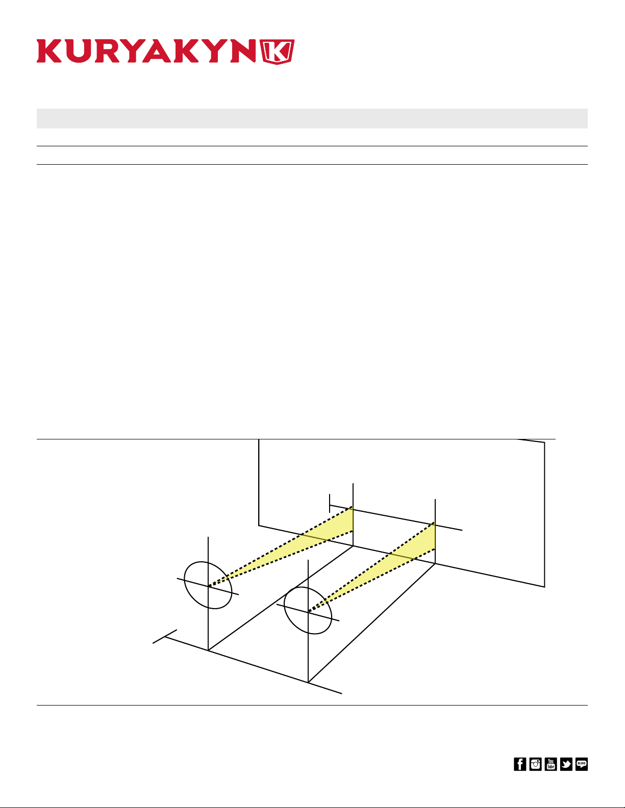
STEP 23 Locate provided PRISM+ 8” Flex-Strip Lights. Determine
areas of the vehicle you wish to apply the lights to. Test t
the lights and mark the desired locations with masking tape.
Determine which provided extension cords and connectors
will be suitable for your desired locations. Make adjustments
to placement where needed. DO NOT INSTALL PARTS AT
THIS TIME!
Note: Refer to FIG 1 for a suggestion, not a requirement, of
where to install Prism+ lights. Get creative and have fun!
ENSURE PROPER ADHESION OF THIS PRODUCT. REMOVE
ALL GREASE, OIL, BUGS, DIRT, AND OTHER DEBRIS
(INCLUDING WAX AND POLISH) FROM THE INSTALLATION
AREA. KURYAKYN WILL NOT PROVIDE WARRANTY
COVERAGE ON PRODUCTS OR COMPONENTS LOST OR
DAMAGED DUE TO IMPROPER INSTALLATION.
DO NOT ATTEMPT THIS INSTALLATION IN TEMPERATURES
BELOW 50°F (10°C). PROPER ADHESIVE BONDING ONLY
OCCURS ABOVE 50°F (10°C).
STEP 24 Using warm soapy water and a clean rag, remove all dirt
and debris from the installation area for the 8” strip lights;
allow the area to dry completely.
STEP 25 Double check placement of the strip lights, and needed
extension cords, before applying the lights to any surface.
STEP 26 Use your ngernail to rub the adhesive backing; this will
activate the adhesive. Do not remove backing until actually
placing lights on vehicle.
STEP 27 Connect lights to the extension cords. Double check
placement of the strip lights, and needed extension cords,
before applying the lights to any surface.
STEP 28 Remove and discard backing from light’s adhesive backer.
Align and place light to vehicle. Press into place for one
minute; full bonding will occur after 24 hours.
Note: If the vehicle is going to be operated before full bonding
occurs, secure the strip lights to the vehicle with a good quality
masking or painter’s tape.
STEP 29 Refer to PIC 22. Locate (2) two provided loop connectors.
For the strip lights on the rear left and rear right channels,
connect a loop connector on the very last light of the
connection of cords and lights. Be sure the raised dot on
the Loop Connector is aligned with the K-shield logo on the
light.
PIC 22
FIG 1
LOOP CONNECTORSTRIP LIGHT
2480

PAGE 7
302480
DPF-MRK-003 REV A 7/23/20
NIGHTCRAWLERS HEADLIGHT AND ACCENT LIGHT KIT FOR JEEP
866 277 9598 | INFO@KURYAKYN.COM
454 COUNTY ROAD VV SOMERSET, WI 54025
KURYAKYN.COM
INSTALLATION INSTRUCTIONS
-CONTINUED-
STEP 30 Refer to PIC 23 and 24. Determine placement of the Prism+
Remote. Disconnect the remote from it’s long extension
cord. Set the remote in desired location, but do not install
it. Feed the remote’s plug into the inner frame area under
the hood, and back to the extension cord from which it was
disconnected from. Connect remote to bluetooth controller.
Note: If you want the remote’s power switch to be inside the
interior of the vehicle, there may be an existing hole with a
grommet in the re wall that you can pass the remote’s plug
through. If an existing hole/grommet does not exist, you may
need to drill a small hole through the re wall for you to pass
the remote’s plug through.
STEP 31 Test functionality of the remote.
STEP 32 Refer to PIC 25. Remove and discard adhesive backer from
the Prism+ Remote. Align and place in desired location.
Press into place for one minute; full bonding will occur after
24 hours.
STEP 33 Locate provided cable ties and cable tie mounts. Secure all
cords in a safe place. Ensure that cords are secured away
from any moving parts, excessive heat or pinch points.
SECURE ALL WIRING AWAY FROM ANY MOVING PARTS,
PINCH POINTS OR EXTREME HEAT. KURYAKYN WILL NOT
ISSUE A WARRANTY ON ANY ELECTRICAL COMPONENT
THAT FAILS DUE TO PINCHED, CRIMPED, BROKEN,
ABRADED, MELTED OR FRAYED WIRES.
STEP 34 Retest function of lights. Ensure all of the lights properly
function before operating vehicle.
STEP 35 Adjust the aim of the headlights. Refer to instructions and
FIG 2 on page 8, or refer to your vehicle’s service manual,
for additional help.
STEP 36 If applicable, reinstall the vehicle’s grill or outer trim rings
reusing parts and hardware that were removed in Step 2.
IT IS THE INSTALLER’S RESPONSIBILITY TO ENSURE THAT
ALL OF THE FASTENERS (INCLUDING PRE-ASSEMBLED) ARE
TIGHTENED BEFORE OPERATION OF THE MOTORCYCLE.
KURYAKYN WILL NOT PROVIDE WARRANTY COVERAGE
ON PRODUCTS OR COMPONENTS LOST DUE TO IMPROPER
INSTALLATION OR LACK OF MAINTENANCE. PERIODIC
INSPECTION AND MAINTENANCE ARE REQUIRED ON ALL
FASTENERS.
PIC 23
PIC 24
PIC 25
FINAL
DETERMINE
PLACEMENT OF
REMOTE AND
REMOVE ADHESIVE
BACKER FOR FINAL
PLACEMENT
2480

PAGE 8
302480
DPF-MRK-003 REV A 7/23/20
NIGHTCRAWLERS HEADLIGHT AND ACCENT LIGHT KIT FOR JEEP
866 277 9598 | INFO@KURYAKYN.COM
454 COUNTY ROAD VV SOMERSET, WI 54025
KURYAKYN.COM
INSTALLATION INSTRUCTIONS
-CONTINUED-
ADJUSTING HEADLIGHT AIM
Refer to FIG 2. Before adjusting the lights check the following things:
- Proper tire pressure ination.
- No build up of mud, snow, or ice on the under-body of the vehicle.
- No additional cargo weight in the vehicle, except for the driver (no passengers).
- Fuel tank is full.
- The suspension height is correct.
- Parked on a at surface.
Choose a wall that is in minimal light. Tape a line 25 ft. away from, and parallel with, the wall. Park the vehicle
to align with the 25 ft. line. On the parked vehicle measure the distance from the ground to the center of the
headlight. Using masking tape and a level, create a horizontal line on the wall using the ground to center
measurements.
On one of the outside edges of the parked jeep, place a perpendicular line on the 25 ft. marker line. This will be
the vertical zero reference. Make a vertical tape line on the wall in alignment with the vertical zero reference.
Measure the distance between vertical zero reference line and the vertical center of the nearest headlight. Take
this measurement and mark it on the wall. Measure the distance between the vertical center points of both
headlights. Take this measurement and mark the second headlight cross line on the wall.
Make adjustments to the headlight position by tightening or loosening the adjustment torx screw on the headlight
bucket.
The headlight is aligned when the LOW beams are just below the horizontal line on the wall and the HIGH beams
should split the cross hairs on the wall. Verify the headlight’s alignment and adjust it if necessary.
DESCRIPTION
FIG 2
2480

PAGE 9
302480
DPF-MRK-003 REV A 7/23/20
NIGHTCRAWLERS HEADLIGHT AND ACCENT LIGHT KIT FOR JEEP
866 277 9598 | INFO@KURYAKYN.COM
454 COUNTY ROAD VV SOMERSET, WI 54025
KURYAKYN.COM
INSTALLATION INSTRUCTIONS
LIMITED WARRANTY
Kuryakyn warrants that any Kuryakyn products sold hereunder, shall be free of defects in materials & workmanship for a period of one (1) year from the date
of purchase by the consumer excepting the following provisions:
1. Kuryakyn shall have no obligation in the event the customer is unable to provide a receipt showing the date the customer purchased the product(s).
2. The product must be properly installed, maintained & operated under normal conditions.
3. Kuryakyn shall not be liable for any consequential & incidental damages, including labor & paint, resulting from failure of a Kuryakyn product, failure to
deliver, delay in delivery, delivery in nonconforming condition, or for any breach of contract or duty between Kuryakyn & a customer.
4. Kuryakyn products are often intended for use in specic applications. Kuryakyn makes no warranty if a Kuryakyn product is used in applications other
than intended.
5. Kuryakyn electrical products are warranted for one (1) year from the date of purchase by the consumer. L.E.D.’s contained in components of Kuryakyn
products will be warranted for defects in materials & workmanship for 3 years from the date of purchase whereas all other components shall be warranted
for one (1) year.
6. All warranty claims must be directed to the place of purchase. Merchandise sold through internet auction sites or any other unauthorized reseller shall
not carry a Kuryakyn warranty. If unsure, please contact the place of purchase to verify they are an authorized Kuryakyn reseller.
RETURN POLICY
Merchandise determined to be defective may be returned up to one year from the date of purchase. Returns must be processed through original seller.
Returned merchandise for any other reason other than warranty claims must be in like new condition & subject to a 20% restocking fee. All returns are
subject to inspection for determination of full or partial credit. Any returned part that shows evidence of being used or installed contrary to manufacturer’s
instructions, &/or subjected to improper handling, packaging or return shipping by the customer, will not be eligible for exchange, refund or warranty
consideration. All returned electrical items will be inspected & tested. If electrical item is deemed functional, no credit will be issued & item will be returned.
All sales are nal on discontinued or closeout merchandise.
©2015 KURYAKYN HOLDINGS, LLC ALL RIGHTS RESERVED
KURYAKYN, KURYAKYN K logo and the marks appearing on this instruction sheet are registered and common law trademarks of Kuryakyn Holdings except noted third-party trademarks. A full listing of
trademarks and trademark registrations owned by Kuryakyn Holdings can be found at www.kuryakyn.com/legal-notice.
Emissions Notice: The California Air Resources Board (CARB) does not permit the use of aftermarket emission-related parts(s) that alter the performance of OEM emission-related devices unless CARB has
issued an Executive Order, other than on racing vehicles on closed courses. Check your local laws and manufacturer’s information.
Listed Manufacturers and product model names are for reference only. All product and company names are trademarks or registered trademarks of their respective holders. Use of them does not imply any
aliation with or endorsement by them. All specications are subject to change without notice.
For additional information on third-party product and company names, please consult our Web page at www.kuryakyn.com/legal-notice
-CONTINUED-
2480

PAGE 10
302480
DPF-MRK-003 REV A 7/23/20
NIGHTCRAWLERS HEADLIGHT AND ACCENT LIGHT KIT FOR JEEP
866 277 9598 | INFO@KURYAKYN.COM
454 COUNTY ROAD VV SOMERSET, WI 54025
KURYAKYN.COM
INSTALLATION INSTRUCTIONS
-CONTINUED-
FCC WARNING STATEMENT
This equipment has been tested and found to comply with the limits for a Class B digital device,
pursuant to part 15 of the FCC Rules. These limits are designed to provide reasonable protection
against harmful interference in a residential installation. This equipment generates, uses and can
radiate radio frequency energy and if not installed and used in accordance with the instructions,
may cause harmful interference to radio communications. However there is no guarantee that
interference will not occur in particular installation. If this equipment does cause harmful
interference to radio or television reception, which can be determined by turning the equipment o
and on, the user is encouraged to try to correct the interference by one or more of the following
measures:
• Reorient or relocate the receiving antenna.
• Increase the separation between the equipment and receiver.
• Connect the equipment into an outlet on a circuit dierent from that to which the receiver
is connected.
• Consult the dealer or an experienced radio/TV technician for help.
CAUTION: any changes or modications to this device not explicitly approved by manufacturer
could void your authority to operate this equipment. This device complies with part 15 of the FCC
Rules. Operation is subject to the following two conditions: (1) this device may no cause harmful
interference, and (2) this device must accept any interference received, including interference that
may cause undesired operation.
The device has been evaluated to meet general RF exposure requirement. The device can be used
in portable exposure condition without restriction.
2480

PAGE 11
302480
DPF-MRK-003 REV A 7/23/20
NIGHTCRAWLERS HEADLIGHT AND ACCENT LIGHT KIT FOR JEEP
866 277 9598 | INFO@KURYAKYN.COM
454 COUNTY ROAD VV SOMERSET, WI 54025
KURYAKYN.COM
INSTALLATION INSTRUCTIONS
-CONTINUED-
PRISM COMPONENTS L.E.D. COUNT
HEADLIGHT 7” 48
ROULETTE 16
FLARE 8
4” STRIP 8
8” STRIP 16
POD* 8 L.E.D. COUNT
(*4 CONTROLLER READ COUNT)
*The bluetooth controller reads a pod light as 4 L.E.D.s, even
though they have a total of 8 L.E.D.s.
CREATING A SINGLE CHAIN OF PODS AND/OR STRIP
LIGHTS:
Refer to FIG 1.1. Do not exceed the 100 L.E.D. maximum
capacity per channel. Place a loop connector on the very end of
the chain of lights.
LF
1
RF
2
LR
3
RR
4
444
CREATING A SINGLE CHAIN OF PODS AND/OR STRIP
LIGHTS WITH A HEADLIGHT, ROULETTE WHEEL, OR
FLARE LIGHT:
Refer to FIG 2.1. Do not exceed the 100 L.E.D. maximum
capacity per channel. Place Headlight or Roulette Wheel on the
end of the chain.
LF
1
RF
2
LR
3
RR
4
4 4 4 48
USING A Y-CONNECTOR WITH A HEADLIGHT, THE
PASSING LIGHTS, A ROULETTE WHEEL, OR THE
FLARE LIGHTS:
Refer to FIG 3.1. When Y-Connectors are used with a Headlight,
the Passing Lights, a Roulette Wheel, or the Flare Lights, each
branch of the Y-Connector needs to have the same amount
of L.E.D.s to function properly. Lights can be placed before a
Y-Connector as long as the 100 L.E.D. maximum capacity per
channel is not exceeded.
When balancing a branch using Pod Lights the controller reads
them as 4 L.E.D.s, but the actual count is 8 L.E.D.s per Pod. The
8 count is used in the overall total of L.E.D.s on a channel. Make
sure not to exceed the 100 L.E.D. maximum capacity
per channel.
LF
1
RF
2
LR
3
RR
4
8 8 8
8 8 8 48
LF
1
RF
2
LR
3
RR
4
4 4 4
4
4
4
LF
1
RF
2
LR
3
RR
4
4 4 4
4
4 4 4 4
4
4 4
USING A Y-CONNECTOR WITH PODS AND/OR STRIP
LIGHTS ONLY:
Refer to FIG 4.1 and 4.2. When using Y-Connectors, the branch
with the most L.E.D.s on it needs to have a loop connector
added to the end of it.
REFER TO THE L.E.D. COUNT TABLE FOR EACH VARIATION OF PRISM+ LIGHTS. BLUETOOTH CONTROLLERS
HAVE A MAX CAPACITY OF 250 L.E.D.S CONNECTED TO IT AT A TIME. MAX CAPACITY PER CHANNEL IS 100 L.E.D.S,
BUT THE CONTROLLER SHOULD NEVER EXCEED A TOTAL OF 250 L.E.D.S CONNECTED TO IT.
FIG 1.1
FIG 2.1
FIG 3.1
FIG 4.1
FIG 4.2
LOOP
CONNECTOR
LOOP
CONNECTOR
LOOP
CONNECTOR
SINGULAR Y-CONNECTOR EXAMPLE
MULTIPLE Y-CONNECTORS EXAMPLE
96 L.E.D.S ON
ONE CHANNEL
SHOWN
6x 4” STRIPS = 1 HEADLIGHT
2480
Table of contents
Other Kuryakyn Automobile Accessories manuals