manuals.online logo
Brands
  1. Home
  2. •
  3. Brands
  4. •
  5. Kuryakyn
  6. •
  7. Automobile Accessories
  8. •
  9. Kuryakyn 9411 Service manual

Kuryakyn 9411 Service manual

INSTALLATION
CUSTOMER SERVICE
877.370.3604 (toll free)
INSTALLATION QUESTIONS
techsupport@kuryakyn.com
or call 715.247.2983
LIMITED WARRANTY
Küryakyn warrants that any Küryakyn products sold
hereunder, shall be free of defects in materials and
workmanship for a period of one (1) year from the
date of purchase by the consumer excepting the
following provisions:
•Küryakyn shall have no obligation in the event
the customer is unable to provide a receipt showing
the date the customer purchased the product(s).
•The product must be properly installed,
maintained and operated under normal conditions.
•Küryakyn makes no warranty, expressed or
implied, with respect to any gold plated products.
•Küryakyn shall not be liable for any consequential
and incidental damages, including labor and
paint, resulting from failure of a Küryakyn product,
failure to deliver, delay in delivery, delivery in
nonconforming condition, or for any breech of con-
tract or duty between Küryakyn and a customer.
•Küryakyn products are often intended for use
in specific applications. Küryakyn makes no
warranty if a Küryakyn product is used in
applications other than intended.
•Küryakyn electrical products are warranted for
one (1) year from the date of purchase by the con-
sumer. Components of Küryakyn products containing
L.E.D.s will be warranted for defects in materials and
workmanship for 3 years from the date of purchase.
•Küryakyn makes no warranty of any kind in
regard to other manufacturer’s products distributed
by Küryakyn. Küryakyn will pass on all warranties
made by the manufacturer and where possible, will
expedite the claim on behalf of the customer,
but ultimately, responsibility for disposition of the
warranty claim lies with the manufacturer.
ABOUT OUR CATALOG
You’ll find all our innovations for H-D, GL and
Metric Cruisers in our annual catalogs. Order
online today–select the ”CATALOGS” icon. Each
Küryakyn®product comes with a Proof-of-Purchase
good for a complimentary catalog.
Details in packaging.
Be sure to ask your local dealer about other
Küryakyn®products, the motorcycle parts and
accessories designed for riders by riders.
©2005 Küryakyn USA®All Rights reserved.
PARTS INCLUDED
1 Pro Hypercharger Assembly
1 Throttle Body Adapter
1 Hardware Kit
3 1/4-20 x 1/2" Socket Head Cap Screws (SHCS)
4 M5 x .80 x 16MM Hex Flange Screws
2 10-24 x .40 Button Socket Cap Screws (BSCS)
1 14" Long 5/32" Rubber Hose
1 Gasket with Adhesive
1 1/8" Chrome EFI Nipple
1 90 Degree Elbow
1 Vinyl Cap
1 1" Clevis
1 Installation Instructions
Please read and understand entire instructions before starting installation.
ThANk YOU fOR ChOOSING küRYAkYN!
IN ORDER TO PROTECT YOU AND OThERS fROM POSSIBLE INjURY
AND/OR PROPERTY DAMAGE OR LOSS, PLEASE PAY CLOSE ATTENTION
TO ALL INSTRUCTIONS, WARNINGS, CAUTIONS AND ATTENTION NOTES
REGARDING ThE USE AND CARE Of ThIS PRODUCT.
WARNING! THIS INDICATION ALERTS YOU TO THE FACT THAT IGNORING THE
CONTENTS DESCRIBED HEREIN CAN RESULT IN POTENTIAL DEATH OR SERIOUS INJURY.
CAUTION! This indication alerts you to the fact that ignoring the contents described herein
can result in potential injury or material damage.
ATTENTION!
This indication alerts you to the fact that ignoring the contents described herein
may negatively affect product performance and functionality.
TOOLS SUGGESTED
Set of Hex Wrenches, Combination Wrenches, Socket Set and Ratchet
STRICTLY OBSERVE ThE fOLLOWING GUIDELINES IN ORDER TO USE ThE
PRODUCT PROPERLY AND AVOID POTENTIALLY DANGEROUS ACCIDENTS.
PROCEDURE
STEP 1 Read and understand all steps in the instructions before starting the installation. Park
the motorcycle on a hard, level surface; turn off the ignition and allow the engine to cool.
NOTE
Some of our high performance air cleaners extend beyond the stock/OEM unit
to achieve smoother airflow and better performance. Riding position may be
affected.
NOTE
The addition of this air cleaner may change the fuel requirements of the engine.
For best drivability and performance.
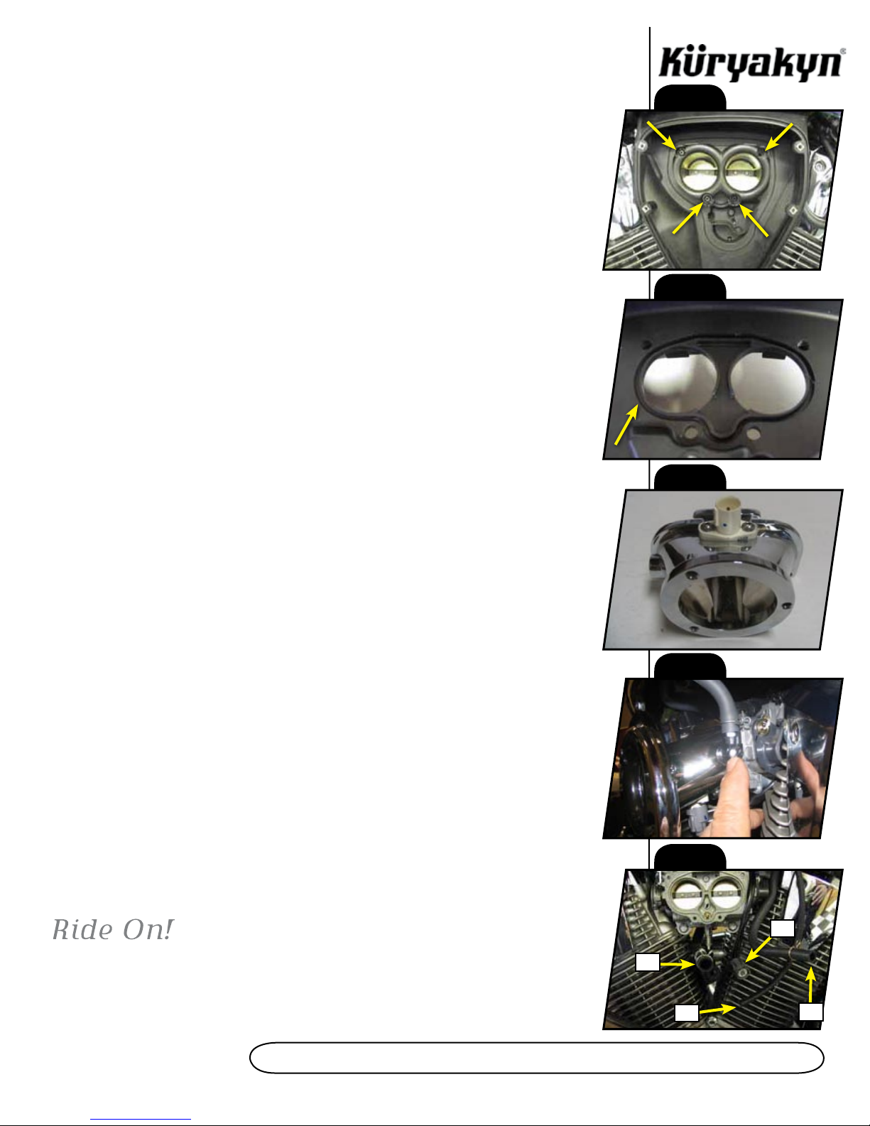
STEP 2 Remove the seat and the rear mounting bolt of the fuel tank.
9411-15MC-0110
PRO SERIES hYPERChARGER 9411
-cont.-
fITS: ALL ‘02-UP VTX1800 MODELS
INSTALLATION
STEP 3 Either prop the rear of the tank up, or have an assistant hold the rear of the tank up. (See PIC.1.)
Remove the four Phillips head screws form the “air horn” assembly in the stock air cleaner backing plate.
Gently “tug” outward at the bottom of the stock air cleaner back and it will become free from the bike,
only to be connected by hoses and a wire harness. Remove the three hoses from the backing plate
as well as the plug from the air mass (temp) sensor. The stock backing plate may now be removed
from the motorcycle, and the tank may now be returned to its original position and re-connected.
The stock backing plate will be able to be removed by just holding up on the back side of the fuel
tank, but it will be a tight fit.
STEP 4 See PIC.2, and PIC.3. Remove the white plastic air mass (temp) sensor and the O-ring
from the stock backing plate. Install the O-ring into corresponding groove in the new cast throttle
body adapter. Install the air mass sensor into the adapter at this time using the 10 x 24 B.S.C.H.
Install the chrome elbow into the manifold then the nipple into the elbow. Make sure to point the
nipple up. Your crank case ventilation hose should be rerouted over the top of the throttle body
so it can be plugged into this nipple. See PIC.4.
STEP 5 See PIC.5. The largest diameter hose (marked as A) will be capped off using the vinyl
cap included in the kit. (PIC.6) The mass air sensor plug (marked as D) is shown in PIC.5. The
intermediate size hose (marked as B, about 3/8” I.D.) will be plugged into the nipple you have
installed on the throttle body adaptor (this is your crankcase breather). Follow the vacuum line
down from the cold start sensor, under tank, to where it connects to the vacuum nipple at the top
of the intake manifold between the two cylinders. Remove the hose from that vacuum nipple and
plug with the 1” pin supplied then stow under tank. Plug the 14” section of hose included with
the Hypercharger kit to the intake manifold nipple as shown in PIC.7. The smallest hose (marked
as C — approximately 1/4” outside diameter) is the hyper vacuum hose. The remaining end will
later be connected to the vacuum pod on the Hypercharger in STEP 7. DO NOT REUSE ANY
Of ThE STOCk VACUUM LINES OR ThE “T” fITTING OR ThE BUTTERfLIES
WILL NOT OPERATE. USE A WIRE TIE TO SECURE ThE DISCONNECTED STOCk
VACUUM LINES.
STEP 6 This step will require some patience as you will be working in a very limited space. See
PIC.8. Start one of the M5 hex flange bolts in one of the two lower mounting holes of the throttle
body. Slide a corresponding slot on the throttle body adapter on to this bolt. Start the remaining
three bolts in the adapter mounting holes. Screw the BOTTOM two mounting screws in all the
way — it may be easier for you to hold the adapter out away from the throttle body as you run
these screws in. You will most likely have to use your open-end wrench and move the fasteners
about 1/6 of a turn at a time. Once the bottom two screws are in all the way, but not tightened,
you may thread the top two mounting screws in. Tighten all four screws, but do not over tighten
— if you snap or strip one of these screws, you will have to repeat this process.
STEP 7 Separate the two halves of the Hypercharger body and remove the filter element. A
5/32” Allen wrench will be used to remove the three “Flat head” Allen bolts on the outer cover
of the Hypercharger, and a 7/64” Allen wrench is used to remove the fasteners from the bearing
cups on the top and bottom of the butterfly shaft. Once you have mounted the back plate to the
throttle body adapter using the three fasteners provided in the assembly, replace the filter element,
and reassemble the Hypercharger.
STEP 8 Connect the vacuum line to the nipple on the bottom of the vacuum pod on the back of
the Hypercharger with the small hose marked "C" in PIC.5.
ATTENTION!
It is the installer’s responsibility to ensure that all of the fasteners (including
pre-assembled) are tightened before operation of the motorcycle. Küryakyn will not warranty
components lost due to improper installation. Periodic maintenance may be required.
PRO SERIES hYPERChARGER
PIC. 1
PIC. 2
PIC. 3
PIC. 4
PIC. 5
A
B
C
D
INSTALLATION
PIC. 6
PIC. 7
VACUUM
SOURCE FOR
HYPERCHARGER
PIC. 8
PAGE
3
PRO SERIES hYPERChARGER

Other Kuryakyn Automobile Accessories manuals

Kuryakyn 4039 User manual

Kuryakyn

Kuryakyn 4039 User manual

Kuryakyn PRISM+ PRO KIT WITH CONTROLLER User manual

Kuryakyn

Kuryakyn PRISM+ PRO KIT WITH CONTROLLER User manual

Kuryakyn Wolo Bad Boy 7743 User manual

Kuryakyn

Kuryakyn Wolo Bad Boy 7743 User manual

Kuryakyn 2480 User manual

Kuryakyn

Kuryakyn 2480 User manual

Kuryakyn 9411 Service manual

Kuryakyn

Kuryakyn 9411 Service manual

Popular Automobile Accessories manuals by other brands

Mercedes-Benz 5168 Fitting instructions

Mercedes-Benz

Mercedes-Benz 5168 Fitting instructions

Akyga AK-EC-14 user manual

Akyga

Akyga AK-EC-14 user manual

BraunAbility Rampvan Maintenance and service manual

BraunAbility

BraunAbility Rampvan Maintenance and service manual

Fiamma Carry-Bike VW T5 D Installation and usage instructions

Fiamma

Fiamma Carry-Bike VW T5 D Installation and usage instructions

Tuff Tonneaus 109 Installation instruction

Tuff Tonneaus

Tuff Tonneaus 109 Installation instruction

Motoalliance Denali MA11705 manual

Motoalliance

Motoalliance Denali MA11705 manual

Kolpin Outdoors 20049 Product instructions

Kolpin Outdoors

Kolpin Outdoors 20049 Product instructions

DV8 OFFROAD TCTT2-01 Product installation manual

DV8 OFFROAD

DV8 OFFROAD TCTT2-01 Product installation manual

Thule XT 3060 instructions

Thule

Thule XT 3060 instructions

Metra Electronics 99-3306 installation instructions

Metra Electronics

Metra Electronics 99-3306 installation instructions

travall TDG 1458D FITTING INSTRUCTION

travall

travall TDG 1458D FITTING INSTRUCTION

Axxess AXRC-CH1 installation instructions

Axxess

Axxess AXRC-CH1 installation instructions

TRAVELLER TC1001 Installation instruction

TRAVELLER

TRAVELLER TC1001 Installation instruction

LAS 10637 operating instructions

LAS

LAS 10637 operating instructions

Connects2 Connects2Vision CAM-PO1 user manual

Connects2

Connects2 Connects2Vision CAM-PO1 user manual

BRP Sea-Doo MOVE Operator's guide

BRP

BRP Sea-Doo MOVE Operator's guide

Agri-Fab SUPER 17 owner's manual

Agri-Fab

Agri-Fab SUPER 17 owner's manual

Vauxhall New Crossland Multimedia Navi Pro Infotainment manual

Vauxhall

Vauxhall New Crossland Multimedia Navi Pro Infotainment manual

manuals.online logo
manuals.online logoBrands
  • About & Mission
  • Contact us
  • Privacy Policy
  • Terms and Conditions

Copyright 2025 Manuals.Online. All Rights Reserved.