EN Instruction Manual
Hydropneumatic tool for rivet nuts from M3 to M10
with stroke and pressure adjustment
FASTSETM10
www.kvt-fastening.ch 3
CONTENTS
1 -GENERAL INFORMATION PAG.97
1.1 ASSISTANCE
1.2 CERTIFICATION AND EC MARKING
1.3 WARRANTY
1.4 MANUAL STRUCTURE
1.4.1 PURPOSE AND CONTENTS
1.4.2 RECEIVERS
1.4.3 PLACING OF THE MANUAL
1.4.4 SYMBOLS USED
2 -TOOL DESCRIPTION PAG.99
2.1 OPERATING SYSTEM
2.2 VIBRATION
2.3 NOISE LEVEL
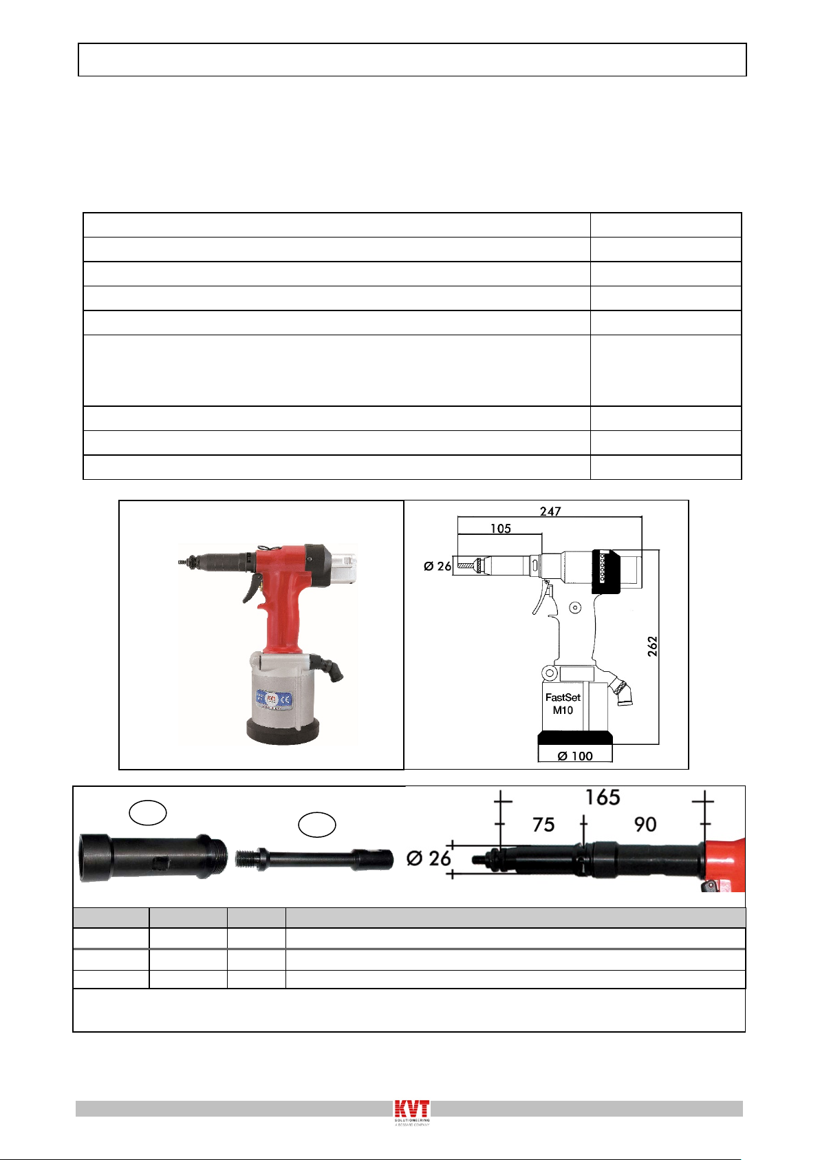
2.4 TECHNICAL DATA
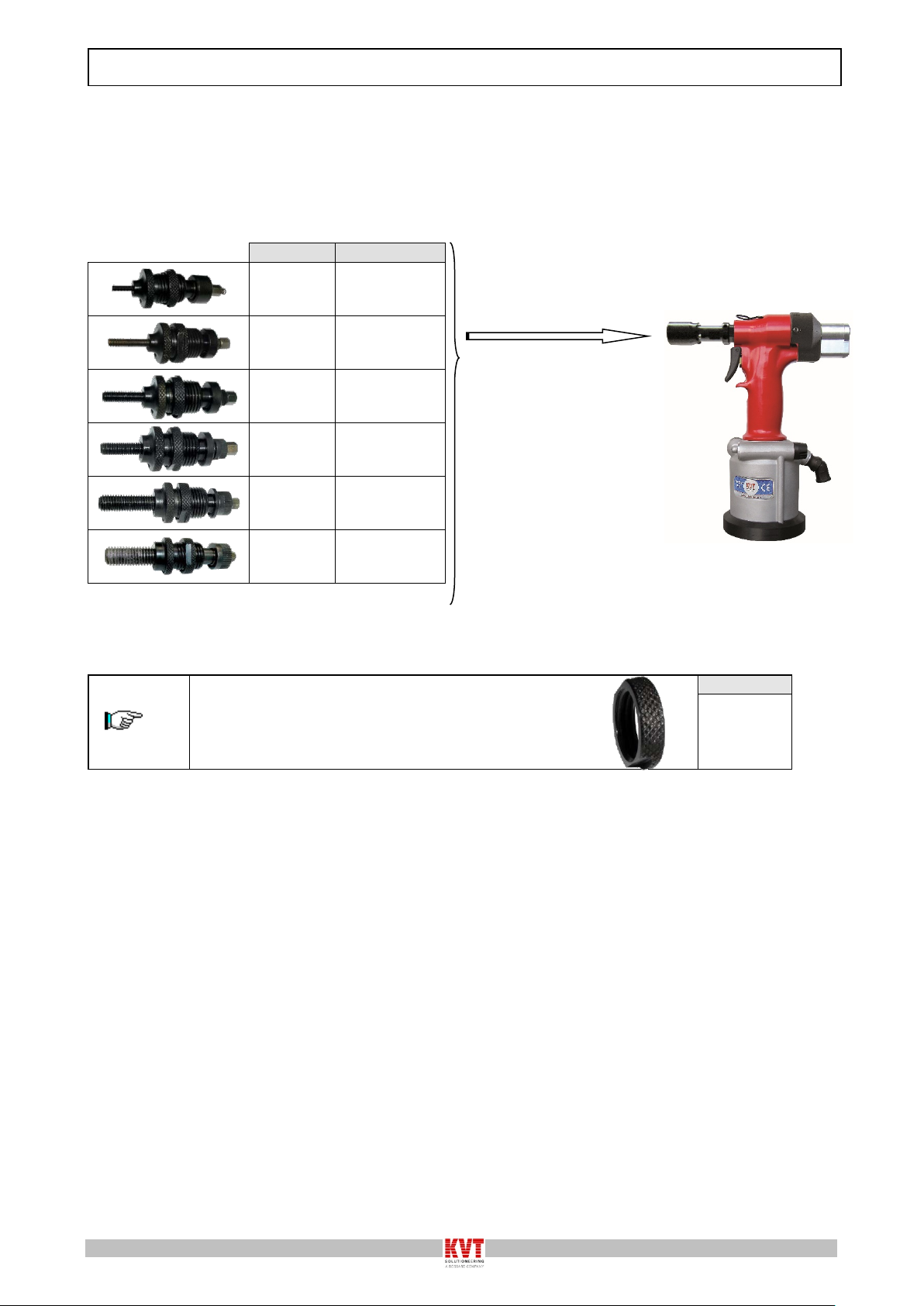
2.5 NOSE ASSEMBLIES AND STANDARD ACCESSORIES
2.5.1 ACCESSORIES ON REQUEST
2.5.1.1 FOR THREADED RIVET NUTS PLACING
2.5.1.1.1 KIT FOR THREADED RIVET NUTS M3
2.5.1.1.1.1 COMPOSITION KIT M3
2.5.1.1.2 KIT FOR THREADED RIVET NUTS M4
2.5.1.1.2.1 COMPOSITION KIT M4
2.5.1.1.3 KIT FOR THREADED RIVET NUTS M5
2.5.1.1.3.1 COMPOSITION KIT M5
2.5.1.1.4 KIT FOR THREADED RIVET NUTS M6
2.5.1.1.4.1 COMPOSITION KIT M6
2.5.1.1.5 KIT FOR THREADED RIVET NUTS M8
2.5.1.1.5.1 COMPOSITION KIT M8
2.5.1.1.6 KIT FOR THREADED RIVET NUTS M10
2.5.1.1.6.1 COMPOSITION KIT M10
2.5.1.2 FOR MALE RIVET NUTS PLACING
2.5.1.2.1 KIT FOR MALE RIVET NUTS M4
2.5.1.2.1.1 COMPOSITION KIT M4
2.5.1.2.2 KIT FOR MALE RIVET NUTS M5
2.5.1.2.2.1 COMPOSITION KIT M5
2.5.1.2.3 KIT FOR MALE RIVET NUTS M6
2.5.1.2.3.1 COMPOSITION KIT M6
2.5.1.2.4 KIT FOR MALE RIVET NUTS M8
2.5.1.2.4.1 COMPOSITION KIT M8
2.5.1.2.5 KIT FOR MALE RIVET NUTS M10
2.5.1.2.5.1 COMPOSITION KIT M410
2.5.1.3 HEAD EXTENSIONS
3 -SPARE PARTS PAG.116
3.1 SPARE PARTS
3.1.1 QUICK KIT COMPLETE WITH SPRING
3.1.1.1 QUICK KIT COMPLETE WITH SPRING
COMPOSITION
3.1.1.1.1 SPECIAL TOOTHED RING NUT FOR
SOCKET CAP SCREWM8.NO NEED FOR REDUCTION
(CODE 3472600) (OPTIONAL)
3.1.2 HIGH RESISTANCE SPECIAL KIT FOR M8WITH
FIXED RING NUT
3.2 SPARE PARTS OF THE MOTOR UNIT (KIT 20)
3.3 ORDERING SPARE PARTS
4 -SAFETY PAG.120
4.1 GENERAL WARNINGS
4.2 INTENDED USE
4.3 OPERATING CONTAINDICATIONS
4.4 RESIDUE RISKS
4.5 IDENTIFICATION/SERIAL NUMBER
5 -INSTALLATION PAG.122
5.1 TRANSPORT AND HANDLING
5.2 STORAGE
5.3 CONNECTIONS
5.3.1 PNEUMATIC
5.4 AIR SUPPLY
5.5 PRELIMINARY CHECKS
6 -OPERATION PAG.123
6.1 OPERATORS
6.2 REPLACEMENT OF STANDARD KIT WITH HIGH
RESISTANCE SPECIAL ONE,FOR M8ONLY (CODE
4508800) WITH FIXED RING NUT:REPLACE
TOOTHED RING NUT (1) WITH THE FIXED ONE (2) +
(3)(SEE PARA 3.1.2)
6.3 TOOL PREPARATION AND SCREW REPLACEMENT
6.4 INFORMATIONS
7 -SERVICING THE TOOL PAG.129
7.1 MAINTENANCE STATUS
7.2 CLEANING
7.3 ORDINARY MAINTENANCE
7.3.1 FILLING THE HYDRAULIC CIRCUIT WITH OIL
7.3.2 PARTS SUBJECT TO WEAR
7.4 MAINTENANCE KIT ON REQUEST
8 -FAULT DIAGNOSIS PAG.133
8.1POSSIBLE FAULTS
9 -FAULT DIAGNOSIS AND REPAIRS PAG.135
9.1 REPAIRS
9.2 REQUESTING ASSISTANCE
10 -DISMANTLING INSTRUCTIONS PAG.135
10.1 DISMANTLING INSTRUCTIONS
11 -ENCLOSED DOCUMENTS PAG.135
11.1 DECLARATION