KYKY ZQJ-2000 User manual


CONTENTS
1 Introduction········································································································································1
2 Introduction to ZQJ-2000 Leak Detector ·························································································2
2.1 ZQJ-2000 Leak Detector················································································································2
2.2 Installation of Leak Detector ··········································································································3
2.2.1 Unpacking ································································································································3
2.2.2 Installation ································································································································3
2.2.3 Working Environment ···············································································································4
2.2.4 Storage Environment················································································································4
2.3 Panel Buttons and Display of Leak Detector ·················································································4
2.4 Power Supply and External Interface of Leak Detector ·································································5
2.5 Performance Index of Leak Detector ·····························································································5
3 Working Principle and Mode of Leak Detector···············································································6
3.1 Working Principle of Leak Detector································································································6
3.2 Operating Mode ·····························································································································7
4 Operations of Leak Detector ··········································································································10
4.1 Startup and Shutdown of Leak Detector······················································································10
4.2 Start Measurement ······················································································································10
4.3 Instrument Calibration and Peak··································································································11
5 Menu Description ····························································································································13
5.1 Main Screen·································································································································13
5.2 Calibration Options ······················································································································14
5.2.1 Inside Leak ·····························································································································14
5.2.2 Outside Leak ··························································································································15
5.2.3 Calibration Parameter ············································································································15
5.2.3.1 Calibration Mode···············································································································15
5.2.3.2 Peak & Calibration ············································································································16
5.2.3.3 Calibration Factor ·············································································································16
5.2.3.4 Zero Adjust ·······················································································································17
5.2.3.5 Anode & Focusing ············································································································17
5.2.3.6 Emission Current ··············································································································18
5.3 Setup Options ······························································································································18
5.3.1 Volume Set·····························································································································19
5.3.2 Vent Set··································································································································19
5.3.3 Reject Set·······························································································································20
5.3.4 Volume Set·····························································································································20
5.3.5 Unit Set···································································································································21
5.3.6 Filament Set ···························································································································21
5.3.7 Antipollution Set ·····················································································································22
5.3.8 Interface ·································································································································22
5.3.9 Print Setup······························································································································23
5.3.10 Recovery ······························································································································23
5.3.11 Other Setup ··························································································································24
5.4 Options for Test ···························································································································24
5.4.1 Sensitivity ·······························································································································25
5.4.2 Vacuum Mode ························································································································25
5.4.3 Zero Set··································································································································26
5.4.4 Automatic Test ·······················································································································26
5.4.5 Diagram··································································································································27
5.4.6 Debug·····································································································································27
5.5 Alarm Options ······························································································································28
5.6 Maintenance Item ························································································································28
6 Troubleshooting ······························································································································29
Appendix A Recovery Parameter Table ···························································································30
Appendix B RS232Communication Protocol···················································································31
Appendix C Denition of PLC IO Interface·······················································································37
CONTENTS

01 02
ZQJ-2000 Helium Leak Detector
1 Introduction 2 Introduction to ZQJ-2000 Leak Detector
The Manual is formulated by making use of the following documentation standards
Buttons in the Manual shall be indicated in Bold.
Documentation Standard
Note: It indicates that important information is included during the process of using
Attention: It indicates that improper operation as required may result in disoperation.
Warning: It indicates that improper operation as required may result in loss of system data, false operation or even damage
to instrument.
Danger: It indicates that instrument damage and personal casualty may occur.
Fig. 1: Outline Structure of Instrument
2.1 ZQJ-2000 Leak Detector
ZQJ-2000 Leak Detector is a kind of full-automatic leak detector featuring dual display of LCD and nixie tube, composed of TMP
(model FF25), foreline pump (model PVP-4), MS, combined valves, circuit board, LCD and buttons. The leak detector is internally
installed with RS232 communication interface and PLC IO interface; beside, printer and wireless remote control are also optional.
The outline structure of instrument is shown below with dimension of 645×450×950 (mm) and weight of 80kg.

03 04
ZQJ-2000 Helium Leak Detector
2.2 Installation of Leak Detector
2.2.1 Unpacking
2.2.2 Installation
Packing box is composed of:
◇ZQJ-2000 Leak Detector 1 set
◇Product Certicate 1 piece
◇Test Plate and Sealing Rubber Plate 1 set
◇Spray Gun 1 piece
◇Bladder, latex tubing, connection tubing and water check 1 set
◇Vacuum grease 1 bottle
◇O-type seal ring 1 set
◇Short circuit socket of receiver 1 piece
◇Mains cable of ZQJ-2000 Leak Detector 1 piece
◇Options of ZQJ-2000 Leak Detector (optional) 1 set
◇Operating Manual for ZQJ-2000 Leak Detector 2 pieces
◇Instruction Book for Foreline Pump and Spare Parts 1 piece
Check whether the packing box is intact with complete accessories.
2.2.3 Working Environment
◇Ambient temperature 5~40℃;
◇Relative humidity <80%;
◇Supply Voltage AC220V/50Hz or AC110V/60Hz (According to the power grid in different areas), reliable ground wire
◇Maximum Current 10A
◇The instrument is free of intense electromagnetic interference nearby, or strenuous vibration or corrosive gas; ventilation device
shall be well established to avoid helium interference.
◇It is recommended to connect air outlet of foreline pump to outdoor or other exhaust system via appropriate hose in order to
reduce local helium signal in testing environment.
◇Keep air ventilation in testing environment to reduce the inuence of local helium signal on measuring results.
2.2.4 Storage Environment
◇The ambient temperature should be -15~60℃;
◇The relative humidity : <90%;
◇Where being left unused for a long time, it’s better to store in a dry and dust-free environment; and it is recommended to use it
next time four hours later after startup.
2.3Panel Buttons and Display of Leak Detector
As shown below, front panel is composed of LCD and corresponding menu buttons, display of nixie tube, display of leakage rate
and pressure, indicators and operation buttons.
1-“Leak” button and Indicator 2-“Calibrate” button and Indicator 3-“Zero” button and Indicator
4-“Test” button 5-“Vent” button 6-State Indicator
7- Light Row of Pressure Indicator 8- Light Row of Leakage Rate Indicator 9- Nixie Tube of Leakage Rate Indicator
10- Unit Indicator of Leakage Rate 11/12- Display Operation Buttons 13- LCD
◇LCD: including home screen and multiple sub-screens, used for displaying instrument’s current leakage rate, pressure, various
statuses and all parameter setting, as well as 8 buttons (L1 – L4, R1 – R4) on both sides of the screen;
◇Display of Nixie Tube: Display current leakage rate in digital form (Coefcient and Index);
◇Leakage Rate Pressure Light Row: Display current leakage rate and pressure of TP (Test Port) in simulation form;
◇Indicator: Display current instrument status and unit, etc.;
◇Operation Buttons: Buttons when operating instrument.
Specic installation requirements are shown as follows
Fixation of Leak Detector
Stay away from strong electromagnetic eld
Close to power socket
Keep 20cm interspaces between Leak Detector and wall
Foreline Pump
The air outlet of Foreline pump has been sealed when delivery and
do remove seal cover before startup
As the instrument has already been added with moderate
specialized Foreline pump oil, just conrm oil level is not lower than
minimum scale mark, or else, add pump oil to appropriate scale and
observe if the oil level is appropriate 10 minutes after startup
Power Supply Voltage 220VAC±10%, 50Hz, 8A
Reliably grounding
◇
◇
◇
◇
◇
◇
◇

05 06
ZQJ-2000 Helium Leak Detector
2.4 Power Supply and External Interface of Leak Detector
Power Supply : include mains cable and master switch of Leak Detector;
External Interface: is composed of RS232 interface, PLC IO interface, printer and wireless remote interface. Including, the rst
two interfaces are system standard interfaces; and the latter two ones are optional;
RS232 interface is to realize the connection of leak detector with computer and other equipment featuring standard 232 interface
and control leak detector or read data from leak detector;
PLC IO interface is used to control leak detector with external switch or output digital quantity and analog quantity to external
equipment;
As for RS232 communication protocol, see Appendix B;
As for detailed instructions on PLC IO interface, See Appendix C;
Printer is optional with micro thermal printing mode;
Wireless remote control is to realize remote wireless control of leak detector via radio frequency, which is also optional.
2.5 Performance Index of Leak Detector
◇Minimum Measureable Leakage Rate <2×10-11 Pa·m3/s
◇Response time (to 63% of the signal ≤2s
◇Startup Time <7 min
◇Measure range 1×10-11 -1×10⁻⁵
◇Inlet Pressure 1000Pa
◇Maximum allowable working pressure of MS Lab 3×10⁻² Pa
◇Dimensions 645(W)×450(D)×950(H)
◇Weight 80kg
3 Working Principle and Mode of
Leak Detector
3.1 Working Principle of Leak Detector
ZQJ-2000 Leak Detector is mainly composed of MS Lab system, vacuum system and electric control system, as shown below.
MS Lab System
MS Lab System is the “heart” of leak detector, which is used to generate ion current signal and separate from ion current during
the process of test so as to nally obtain useful helium signal. MS system mainly includes ion source, magnetic analyzer and amplier.
Ion source is composed of lament (tungsten) and ionization box; when leak detector is working, electrons on the surface of lament
will obtain high energy to separate from the surface and these electrons are given with certain speed under the effect of electric eld;
at this time, as being encountered with gas, it will ionize the gas into ion which will access to magnetic analysis lab under the action of
accelerating eld. The magnetic analysis lab is used to separate ions with different mass to charge ratio from each other, receive helium
ion current signals through amplier and transform them into corresponding leakage rate signals by means of amplication processing.
Only under high vacuum environment can MS Lab work normally.
Vacuum System
Vacuum system is mainly composed of TMP, foreline pump, combined valves, vacuum measurement and vacuum line. TMP is
under high-vacuum environment provided by MS Lab to provided air path with different helium signals for different modes of test; foreline
pump is to provide vacuum for TMP and work pieces for evacuated test; combined valves are applied to offer various air paths for test
and vacuum measurement is to provide TP vacuum degree and foreline pump vacuum degree.
◇
◇

07 08
ZQJ-2000 Helium Leak Detector
Electrical Control System
Electrical Control System is mainly composed of system power supply, main board, ion source plate, display panel,
communication board and control software.
Structure chart of system diagram is shown below:
1-MS 2-TMP 3- Thermocouple Gauge
4-Foreline Valve 5-Foreline Pump 6/7 Fine Valve
8/9 Gross Valve 10-TP Pirani Gauge 11- Internal Standard Leak
12-Leak Valve 13-Vent Valve 14-TP
3.2 Operating Mode
By diagram, the Leak Detector is classied into Standby Mode, Pre-pump Mode, Gross Test Mode, Fine Test Mode, Venting
Mode and Internal Reading Leak Mode. System diagrams of various modes are shown below:
Standby: Instrument automatically enters standby mode after startup, and only foreline valve of TMP opens; any fault of
instrument (such as being polluted) may also result in automatic standby state. If the vent valve of instrument is not allowed to be
opened or is to be opened with delay, the instrument will also enter into standby state before opening vent valve.
Roughing pump: The instrument enters into roughing pump state before conducting test, and foreline valve is closed and gross
valve (roughing pump valve) opens at this time.
Gross Test: When the pressure of TP reaches that of gross test before the system enters into gross test mode, both foreline valve
and gross valve open at this time. When the pressure of TP reaches that of gross test after the system enters into gross test mode, the
pressure of TP will continue to decrease until reaching the pressure of ne test, then the instrument will enter into ne test status.
Fine Test

09 10
ZQJ-2000 Helium Leak Detector
Vent: When vent valve is ready, press “Vent” button to enter into vent status, and both foreline valve and vent valve open at this
time.
Internal Reading Leak: Press “Leak” button on the operation manual, the instrument will enter into internal reading leak status, and
foreline valve, ne valve (ne test valve) and leak valve open at this time.
By sensitivity, it is divided into high sensitivity mode and low sensitivity mode; as for the former, the operating speed of TMP is
400HZ, and as for the latter, the operating speed of TMP is 600HZ. The minimum measurable leakage rate as for high sensitivity is
2.0×10⁻¹¹ Pa.m3/s and is 2.0×10⁻¹⁰Pa.m3/s as for low sensitivity. As for settings of high and low sensitivity, see Chapter 5.
4 Operations of Leak Detector
4.1 Startup and Shutdown of Leak Detector
Startup
Before startup, connect mains cable to AC220V or AC110V (According to the power grid in different areas) socket, and guarantee
reliable grounding of instrument; as for the boot for the rst time, guarantee the seal cover at the air vent of foreline pump has been
removed. Switch on Leak Detector in idle mode, then start the instrument with foreline pump operating, screen displaying with “KYKY”,
all nixie tubes and indicators turning on and red light and green light of leakage rate light row being switched. After 3s, all lights turn off,
nixie tubes of instrument displays P-OX and both LCD and nixie tubes display continuous processes of system startup simultaneously,
as shown below:
After the instrument enters normal state, nixie tube displays leakage rate and corresponding values will be displayed on light row of
leakage rate and pressure light row of TP; various indicators will display working conditions and units. LCD enters into home screen; as
for specic screen information, see Chapter 5.
Stop
The instrument can be stopped by switching off idle state in any state; do not remove the instrument in 5 minutes after switching it
off and guarantee that the instrument has been switched off more than 5 minutes before next startup.
4.2 Start Measurement
In order to guarantee Leak Detector is in normal state before using, press “Leak” on the operation panel, and the detector will
automatically open inside leak. If the Leak Detector works normally, the displayed leakage value will be the leak value, which is about
2.0×10⁻⁸pa.m3/s; if the deviation from this value is too large, implement peak or calibration, see 4.3 for specic steps.
1. After Leak Detector remains in normal state, press “Vent” button to keep it in vent state and then connect work piece to TP;
2. Press “Test” button, the instrument starts to pre-pump the work piece and then the pressure changes at the TP will be observed
through LCD or nixie tube;
3. When the TP pressures reaches the setting value of gross test (The Leak Detector is defaulted in ne mode when delivery, and
the TP pressures of gross test and ne test are defaulted with 100pa and 10pa respectively; if such value was changed last time, the
Display of Nixie Tube Display of LCD Remark
P-01 System startup System startup
P-02 Low vacuum normal Foreline pump operates normally
P-03 Startup of TMP TMP works in high speed
P-04 TMP normal Rotating speed of TMP reaches 400Hz
P-05 High vacuum ready Automatically calculate set-up time according to last start-up time
P-06 Ion source power Automatically add lament 1 or 2 according to last setup
P-07 System normal Starting process is completed
P-08 Standby Entering normal detection state

11 12
ZQJ-2000 Helium Leak Detector
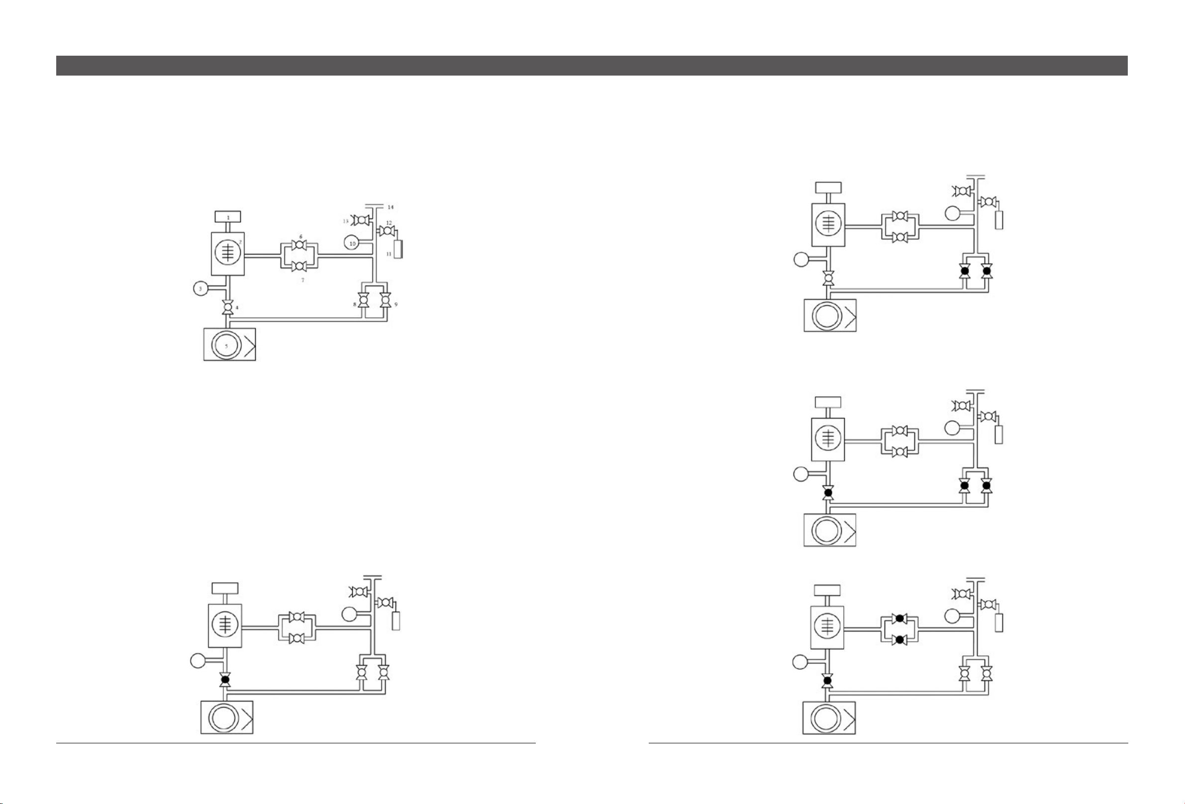
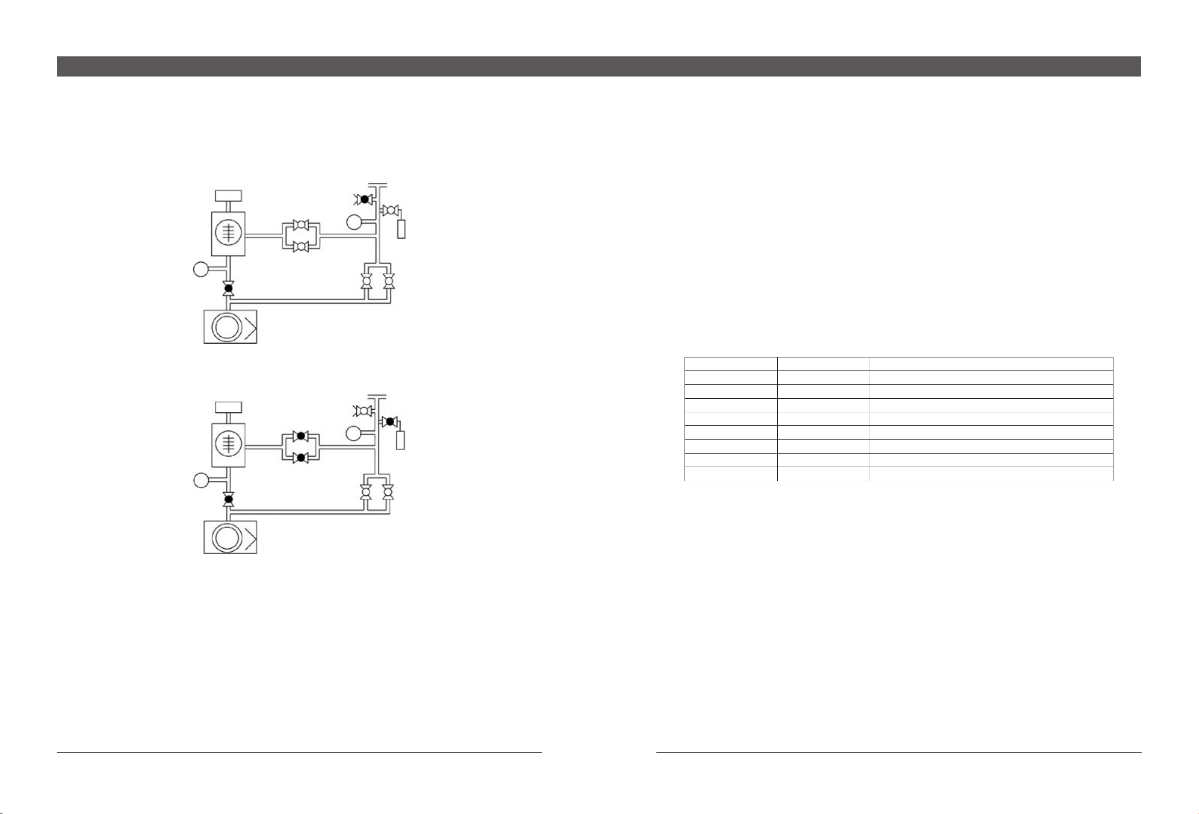
changed value will be used.) Open the gross valve, then TP pressure will continue to be dropped until reaching the setting value of ne
test, ne test valve opens to enter into ne test mode;
4. If work piece to be detected is too big or any leakage of work pieces exist so that TP pressure during pre-pumping process is
unable to reach test state for a long time, in order to prevent foreline valve is in off state for a long time during the pre_pump process,
the system will automatically carry out delayed pre-pump operation in 2 minutes after pre-pumping, which is to close gross valve,
open foreline valve and automatically enter into pre-pump state in 5 seconds; if it is unable to reach test state after several repeated
operations, check if there is any big leakage for the work piece or use auxiliary pump to conduct pre-pumping;
5. After the instrument enters into test state, initiate test on work piece, see Appendix for detailed detection method. Under test
state, it is able to print the detection result (as for instrument equipped with optional printer); just press “Print” button on the main screen
to display “Print”. The instrument will calculate maximum leakage rate automatically; press “Print” button again, the instrument will
print maximum leakage rate between two times of button pressing and related information. See Print Options in Chapter 5 for specic
information.
6. After completing Test, press “Vent” button, if the “Set-up of Vent Valve” is congured with “Vent Enable”, the vent valve will
vent the gas automatically according to the set time and the vent indicator on the panel at this time will turn on; or else, the system will
become in standby state and the standby indicator on the panel will turn on.
4.3 Instrument Calibration and Peak
Before using, it is recommended to implement peak and calibration to guarantee accurate and precise measuring results. The
instrument features automatic peak and calibration function, as well as manual calibration function. See Set-up of Calibration Options in
Chapter 5 for specic information on manual calibration. Both inside leak and outside leak provided by user can be acceptable for peak
and calibration.
Steps on peak or calibration for inside leak are shown below:
1. Set up inside leak parameters (leak value, nominal temperature, manufacture date, temperature correction and annual
attenuation);
2. Set up calibration mode as internal standard;
3. Set up “Peak & Calibration” as Only Calibration or Peak and Calibration;
4. Block TP with blind plate;
5. Press “Calib.” button on the operating panel, the instrument will enter into pre-pumping state while the value for inside leak will
be calibrated automatically in accordance with internal temperature of instrument and current system time and displayed in main screen
as “QL=x.x×10-8pa.m3/s”, where xx refers to the calibrated value;
6. The instrument automatically implements peak or calibration, and other operating buttons except “Vent” button on the operating
panel which is able to end such peak or calibration process will keep invalid. During the process of peak or calibration, the screen will
display current state;
7. After about 1 to 3 minute(s) when peak or calibration is completed, the system will automatically enter into “ne test” state, user
can verify whether the instrument calibration process is correct by pressing “Leak” button.
Steps on peak or calibration for outside leak
1. Set up outside leak parameters (leak value, nominal temperature, manufacture date, temperature correction and annual
attenuation);
2. Set up calibration mode as external standard;
3. Set up “Peak & Calibration” as Only Calibration or Peak and Calibration;
4. Press “Vent” button to connect standard leak with TP;
5. Press “Calibrate” button on the operating panel, the screen will pop up Input Ambient Temperature page, then input the ambient
temperature and press “OK” button, the screen will pop up the message saying “Please open outside leak”, then open manual valve of
outside leak and press “OK” button, the instrument will enter into pre-pump state and automatically calibrate the value of outside leak
based on user input temperature and current system time; besides, such values will be displayed on the main screen with QL=x.x×10-
8pa.m3/s, where xx refers to the calibrated value.
6. The instrument automatically implements peak or calibration. During such process, the message “Close outside leak” will be
popped up automatically on the screen, close the manual valve of leak, the system will automatically search for the background and
other operating buttons except “Vent” button on the operating panel which is able to end such peak or calibration process will keep
invalid. During the process of peak or calibration, the screen will display current state;
7. After about 1-3 minutes when peak or calibration is completed, the system will automatically enter into “ne test” state, user can
open manual valve of outside leak and verify whether the instrument calibration process is correct by pressing “Test” button.

13 14
ZQJ-2000 Helium Leak Detector
5 Menu Description
ZQJ-2000 Leak Detector is set up with rich parameters which can be stored in parameter storage area after being congured even
in case of power failure; the instrument can automatically read last congured parameters as startup next time. These parameters can
be set up in any state, besides, the instrument is also equipped with automatic recovery of parameters, which is to recover initial system
parameters automatically via password validation, see Appendix for initial parameter values of instrument in detail.
5.1 Main Screen
Five menu options including “Calibration”, “Test”, “Setup”, “Alarm” and “Maintenance” as well as “Print” and “Sound Volume” buttons
are displayed on the screen. Operating buttons (L1–L4 and R1–R4) correspond to such menus, which can be operated accordingly.
The display of leakage value, TP pressure and operating state of system are located in the center of screen and other information
including system date and time, internal temperature of instrument, current speaker volume, Reject Point, vacuum degree of MS lab,
PLC IO interface state, RS232 state, lament state and communication state between display panel and mainboard is displayed at the
bottom of the screen.
◇System time: The instrument is equipped with built-in real-time clock chip, which is able to ensure accurate operating time under
any state (even in case of power failure);
◇Internal Temperature of instrument: The instrument is installed with built-in temperature sensor, which is capable for precisely
measuring the temperature changes inside the instrument and providing temperature correction for inside leak calibration;
◇Speaker Volume: If the speaker volume is set up in On state, it is able to increase volume by L3 and decrease volume by R3;
◇Reject Point: Two Reject Points are congured inside the instrument, namely Reject Point 1 and Reject Point 2; when any Reject
Point is set up, corresponding number of Reject Point will be displayed;
◇Vacuum Degree of MS Lab: It is indicated in the form of M0 – M9, where 0 and 9 refer to best and worst vacuum degree. When
the degree achieves 9, the system will cut off lament automatically;
◇PLC IO Interface State: When enabling PLC IO interface, IO characters will be displayed accordingly;
◇RS232 Interface State: When enabling RS 232 interface, 232 characters will be displayed accordingly;
◇Filament State: The system will automatically detect whether the filament has been added successfully and which type of
lament has been used;
◇Communication State between Plates: Where the communication between mainboard and display panel remain normal, the
symbol will ash automatically.
5.2 Calibration Options
Press L1 button on the main screen to go to calibration option, which is composed of submenu of Inside leak, Outside leak and
Calibration Parameter. Press menu button to access corresponding page.
5.2.1 Inside Leak
Inside leak parameters are mainly used to automatically calibrate actual leakage rate according to current environment when using
peak and calibration of inside leak, so as to make calibrated result more accurate. Press L2 to go to setup of inside leak parameters,
which are composed of leakage rate of internal standard leak, nominal temperature, manufacture date, temperature correction and
annual attenuation. All parameters mentioned above shall be consistent with the nominal values on the internal standard leak of
instrument.
Press L1 and R1 corresponding to up and down button to move cursor and press L3 and R3 corresponding to Plus and Minus sign
to change value. After correction, press L4 corresponding to “OK” button to complete the setup of inside leak parameters. Press R4
corresponding to Return button to return to previous menu directly for cancelation.

15 16
ZQJ-2000 Helium Leak Detector
5.2.2 Outside Leak
Outside leak parameters are mainly used to automatically calibrate actual leakage rate according to current environment when
using peak and calibration of outside leak, so as to make calibrated result more accurate. Press R2 to go to setup of outside leak
parameters, which are composed of leakage rate of outside standard leak, nominal temperature, manufacture date, temperature
correction and annual attenuation. All parameters mentioned above shall be consistent with the nominal values on the standard outside
leak of instrument.
Press L1 and R1 corresponding to up and down button to move cursor and press L3 and R3 corresponding to Plus and Minus sign
to change value. After correction, press L4 corresponding to “OK” button to complete the setup of outside leak parameters. Press R4
corresponding to Return button to return to previous menu directly for cancelation.
5.2.3 Calibration Parameter
In calibration options, press L3 corresponding to Calibration Parameter to go to setup of six calibration parameters, which include
Calibration Mode, Peak & Calibration, Calibration Factor, Zero Adjust, Anode voltage and Emission Current.
5.2.3.1 Calibration Mode
Press L1 to enter into setup menu of calibration mode, which is divided into inside leak calibration and outside leak calibration. Such
setting shall be applied together with menu of “Peak & Calibration”, “Leak Parameter” and “Calibrate” button. As for internal calibration,
the instrument will carry out peak or calibration via inside leak automatically; as for external calibration, the instrument will implement
peak or calibration via outside leak automatically. Select L1 or L2 button, then press “OK” button to save corresponding setting. Directly
press “Back” for cancelation.
5.2.3.2 Peak & Calibration
Press L1 to go to Peak & Calibration menu, then press L1 to select Calibration Only, when pressing “Calibrate” button on
the operating panel, only calibration will be implemented for the instrument; press L2 to select Peak before Calibration, when press
“Calibrate” button on the operating panel, peak will be carried out before calibration. This option shall be applied together with the
menu of Leak Parameter, Calibration Mode and “Calibrate” button. Press “OK” to save corresponding setup, or “Back” to cancel.
5.2.3.3 Calibration Factor
Press L3 to enter into setup menus of Calibration Factor, which are divided into high-sensitivity calibration factor and low-sensitivity
calibration factor, both of which have their respective gross test and fine test calibration factors. Calibration factors can either be

17 18
ZQJ-2000 Helium Leak Detector
modied automatically based on actual calibration value during the process of automatic calibration, or be corrected manually. Where
the sensitivity is configured as “High”, only high-sensitivity calibration factors can be changed, so is low-sensitivity. As for manual
change, the calibration factors will be changed in real time along with the change of numerical values, press “OK” to accept such
change; or press “Back” to cancel. The range of calibration factor is 0-1000.
Manual Calibration: Before calibration, open inside or outside leak to make the instrument be in the state of test. At this time,
observe the change of leakage rate as changing corresponding factors. Just press “OK” once such rate reaches corrected leak value.
5.2.3.4 Zero Adjust
Press L3 to enter into menu of Zero Adjust, and the zero code can be modied according to actual value automatically or manually.
As for manual adjusting, the background signal of instrument will be changed in real time along with the change of numerical value,
press “OK” to accept such change; or press “Back” to cancel. The range of zero code is 9000 – 15000.
5.2.3.5 Anode voltage
Press R1 to enter into the menu of anode setup, the anode voltage and focus voltage will be modied automatically based on
actually calibrated value during the process of automatic peak or manually as manual peak. As for manual change, the instrument signal
will be changed in real time along with the change of numerical value, press “OK” to accept such change; or press “Back” to cancel.
The ranges of anode voltage and focus voltage are 200-315V and 220-315V respectively.
Manual Peak: Before peak, open inside leak or outside leak to make the instrument be in the state of test. At this time, observe the
change of leakage rate as changing the anode voltage, when the leakage rate reaches the maximum value, change focus voltage to
make the leakage rate maximum. Repeat such steps for several times to obtain helium peak.
5.2.3.6 Emission Current
Press R3 to enter into the setup menu of emission current, which is 0.30mA in default. Change anode current manually to increase
the signal; Press “OK” to accept such change; or “Back” to cancel. The scope of emission current is between 0.20 and 0.99mA.
5.3 Setup Options
On the main screen, press R1 button to go to Setup Options, which is composed of Vacuum Setup, Vent Valve Setup, Reject
Setup, Volume Setup, Unit Setup, Filament Setup, Antipollution Setup, Interface Setup, Print Setup, Recovery Setup and other setup.
The setup menu is displayed in two screens. Just press L3 to switch to next screen and press menu button to go to the page of
corresponding parameter setup.
Setup Page 1
Setup Page 2

19 20
ZQJ-2000 Helium Leak Detector
5.3.1 Volume Set
On setup page 1, press L1 to go to Vacuum Setup page, which is to set up the TP pressure as the instrument enters into gross
test state and ne test state.Gross test pressure is divided into high-sensitivity and low-sensitivity type, and the pressure value shall be
selected automatically depending on sensitivity setup. After completing setup, press “OK” to accept such change; or “Back” to cancel.
The pressure scopes of high-sensitivity and low-sensitivity gross test are 0-200Pa and 0-800Pa respectively, and that of ne test is
0-50Pa.
5.3.2 Vent Set
On setup page 1, press L2 to go to Vent Valve Setup page, which is used to set up the action of vent valve after pressing “Vent”
button on the operating manual. If “Vent Enable” is selected, the vent valve will be opened according to the delayed vent time after
pressing “Vent” button. Or else, no action is made and the instrument will become in standby state after pressing “Vent” button, at
this time, the standby indicator will turn on. For example, if it is allowed to vent with the delayed vent time of 10s, after pressing “Vent”
button under the state of test, the system will go to standby state (with standby indicator on) rstly, then vent valve will be opened in 10s
(vent indicator on).
After completing setup, press “OK” to accept such change; or “Back” to cancel. The setup scope of delayed vent time is 0000 –
9999s.
5.3.3 Reject Set
On setup page 1, press L3 to go to the page of Reject Point Setup, which is used to trigger the output of system alarm point. There
are two reject points, namely Reject Point 1 and Reject Point 2, which is able to be switched by moving up and down arrow. Change the
value of each reject point and press “OK” after completing setup. If the line cursor is at the Reject Point 1, the instrument will compare it
with Reject Point 1 based on current leakage rate. Where the leakage rate is larger than this setup value, alarm output will be triggered
and the leakage rate light row will turn red. At this time, if the volume is set up with “on”, the sound will be changed along with the value
variation of leakage rate.
After completing the setup, press “OK” to accept such change; or “Back” to cancel.
5.3.4 Volume Set
On setup page 1, press R1 to go to the page of Volume Setup, which is composed of Volume setup (mainly used for alarm of reject
point trigger) and buzzer sound (used for button volume and error message alarm). Where the volume is the volume of speaker with
the setting range of 0-9, 0 refers to mute and 9 refers to maximum volume. The volume switch contains On and Off state. Button sound
is also divided into On and Off state. When the button sound is set up with ON, key sound appears for pressing any operating button.
When the button sound is set up with Off, there is no sound for button pressing. But the buzzer will still alarm as error occurs.
After completing the setup, press “OK” to accept such change; or “Back” to cancel.

21 22
ZQJ-2000 Helium Leak Detector
5.3.5 Unit Set
On setup page 1, press R2 to go to the page of Unit Setup, which is composed of Pa, mbar and ttor. Press Plus and Minus Button
to switch; after completing the setup, press “OK” button, then the unit of leakage rate on the screen, nixie tube and light row will be
switched with current setting automatically, and corresponding unit indicator changes accordingly.
After completing the setup, press “OK” to accept such change; or “Back” to cancel.
5.3.6 Filament Set
On setup page 1, press R3 to go to the page of Filament Setup, which is composed of Filament Selection and Filament Switch.
The instrument is equipped with two lament with one for use and the other for backup. When the system detects that the lament
used currently is broken down, it will switch to the other one automatically and corresponding alarm information will be displayed on the
screen. User can replace lament and switch on/off lament manually.
After completing the setup, press “OK” to accept such change; or “Back” to cancel.
5.3.7 Antipollution Set
On setup page 2, press L1 to go to the page of Filament Antipollution Setup, which is composed of “Enable or Disable” and “Leakage
Rate of Alarm Point”. When “Disable” is set, Antipollution setup is inoperative; or else, if the leakage rate detected by the system is
larger than that of being set for alarm point, the system will enter into standby state automatically. The leakage value of alarm point can
be congured according to actual situations. Enabling of antipollution function can prevent large amount of helium from entering into
high vacuum and system background from being impacted by helium pollution.
After completing the setup, press “OK” to accept such change; or “Back” to cancel.
5.3.8 Interface
On setup page 2, press L2 to go to the page of Filament Interface Setup, including PLC IO interface, RS232 interface, Panel
Interface, Print Interface and Remote Interface (unavailable currently). All ve interfaces mentioned above can be enabled or disabled
separately. And operation can be conducted only corresponding interface is enabled.
After completing the setup, press “OK” to accept such change; or “Back” to cancel.

23 24
ZQJ-2000 Helium Leak Detector
5.3.11 Other Setup
On setup page 2, press R2 to go to the page of Other Setup, including the setup of system time and language, which is only serving
with Chinese. The instrument is installed with built-in Calendar Clock, which will be always working and keep in accurate readings
regardless of power on or off. To modify time and date, just use left and right buttons as well as plus and subtract buttons.
After completing the setup, press “OK” to accept such change; or “Back” to cancel.
5.4 Options for Test
On main screen, press L2 to go to setup of Test Options, composed of Sensitivity, Vacuum Mode, Zero Adjust Mode, Auto Test,
System Diagram, System Debugging and Range Selection. Press menu button to enter corresponding parameter setup page.
5.3.9 Print Setup
On setup page 2, press L3 to go to the page of Print Options, which are composed of Type, HLD No., Operator, Work Piece No.,
Bar Code, Leakage Rate, Pressure Value, Reject Point, Evaluation, Standard Leak, Time and Temperature, all of which can be selected
or canceled by Plus or Minus Button. When the system is in test state, press “Print” button on the main screen to print in accordance
with the setup of print options.
The xed value of Type is ZQJ-2000 with default HLD. No. of 001. User can right click to enter into the page of HLD No. Setup;
the Operator is defaulted with 001, user can also go to the page of Operator No. Setup via right-click operation; the initial value of work
piece No. is set up via right-clicking with the scope of 000000-999999, the work piece No. will be added with 1 in automatic sequence for
each print; the format of bar code is EAN 13 as general commodity code; and leakage rate, pressure value, reject point, standard leak,
time and temperature are all current values of the system.
After completing the setup, press “OK” to accept such change; or “Back” to cancel.
5.3.10 Recovery
On setup page 2, press R1 to implement system parameter recovery. Input password (the default initial password is 0000) and
press “OK” after inputting correct password, the system will carry out parameter recovery automatically; after completing in 2 seconds,
the system will go to main screen . As for initial parameter values after recovery, see Appendix A.

25 26
ZQJ-2000 Helium Leak Detector
5.4.3 Zero Set
On test page, press L3 to go to the page of Zero Adjust Setup, it can be congured automatically or manual. As for automatic zero
adjust under test state, if the signal is lower than zero point, the system will compensate for zero code automatically (see zero code in
calibration); as for manual zero adjust, the user can conduct with zero adjust manually via zero code in Calibration.
After completing the setup, press “OK” to accept such change; or “Back” to cancel.
5.4.4 Automatic Test
On test page, press L4 to go to the page of Sensitivity Setup, automatic test mode consists of Automatic Test Switch and Automatic
Test Time. When automatic test switch is set up with N, the system will close the function of automatic test; when the switch is with Y,
the system will open the function. When user presses “Leak” button, the system will end the test process in accordance with automatic
test time after entering the state of test (being in standby or vent state).
After completing the setup, press “OK” to accept such change; or “Back” to cancel.
5.4.1 Sensitivity
On test page, press L1 to go to the page of Sensitivity Setup, which can be congured with High Sensitivity and Low Sensitivity. As
for the former mode, the rotating speed of TMP is 400Hz and the minimum measurable leakage rate is 2×10-11pa.m3/s; as for the latter
mode, the rotating speed of TMP is 600Hz and the minimum measurable leakage rate is 2×10⁻¹⁰pa.m3/s, all of which can be set up via
L1 and L2 button.
After completing the setup, press “OK” to accept such change; or “Back” to cancel.
5.4.2 Vacuum Mode
On test page, press L2 to go to the page of Vacuum Mode Setup, the system features ne test and gross test mode under both
sensitivity modes. Fine test valve (ne valve) opens under ne mode and gross valve (pre-pump valve) opens under gross test mode.
Sniffer mode is set as the gross test mode under low sensitivity. Corresponding diagrams shall be subject to foregoing Test mode, all of
which can be set via L1 and L2 button.
After completing the setup, press “OK” to accept such change; or “Back” to cancel.

27 28
ZQJ-2000 Helium Leak Detector
5.5 Alarm Options
On main screen, press R3 to go to alarm options. See Troubleshooting in Chapter 6 for the meanings of various alarm information.
When any alarm occurs, “Er” will be displayed before corresponding alarm code. Meanwhile, the system buzzer will also send alarm
sound and detailed alarm information will be displayed above the screen. Press any button to eliminate alarm sound, but the alarm
information on the screen can be removed only all alarm has been handled completely.
5.6 Maintenance Item
On main screen, press R4 to go to Maintenance Information page, listing the operating time of main components of system,
including operating time of TMP, foreline pump as well as working time of Filament 1 and Filament 2. User can conduct routine
maintenance in accordance with major components to be operated, such as oil change of TMP and foreline pump. If new part is to be
applied, conduct zero clearing by reset button, which is required with password authorization and is not open to user.
5.4.5 Diagram
On test page, press R1 to go to the page of System Diagram, indicating the overall system diagram and switch status of various
solenoid valves.
5.4.6 Debug
On test page, press R2 to go to the page of System Debugging, which needs password authorization. Only professionals can
conduct such operations. On the page of System Debugging, solenoid valve, TMP and MS Lab can be controlled separately by using
Plus and Subtract button. Non-professional staff is not allowed to enter this page, for it may result in false action of system.
5.4.7 Range Selection
On test page, press R3 to go to the page of Range Selection, which is used to set up the scope of minimum leakage rate to be
displayed, for example, if the range selection is set up with 10, the minimum display of leakage rate is -10.
After completing the setup, press “OK” to accept such change; or “Back” to cancel.

29 30
ZQJ-2000 Helium Leak Detector
SN Fault Message Meaning Solution
1Startup Communication
Fault
Communication between display
panel and mainboard is abnormal
●Check if the wires among Circuit boards are well
connected
●Check mainboard or displayed circuit board
2 Low Vacuum Timeout The foreline pressure of TMP is too
high as startup
●Check foreline pump
●Check foreline thermocouple
3 Fault of TMP It is unable to receive normal signal
of TMP
●Check if any failure of TMP occurs
●Check control line of TMP
4 High Vacuum Timeout The pressure of MS Lab is too high ●Check if any leakage exists in high vacuum
●Check multiple-ion receiver pole
5 Fault of Filament 1 Signal of Filament 1 is weak or
interrupted
●Check ion source and ion source cable
●Check power board of ion source
6 Fault of Filament 2 Signal of Filament 2 is weak or
interrupted
Ditto
7 Filament Fault Both Filament 1 and 2 are broken
down
Ditto
8 Weak Signal The signal is too weak as calibration ●Re-conduct peak
●Check MS Lab
9 Vacuum alarm of MS Lab The pressure of MS Lab is too high ●Check if leakage exists in high vacuum
10 Foreline Vacuum Alarm The foreline pressure of TMP is too
high
●Check foreline thermocouple
11 Zero Adjust Error Zero code is out of range
12 Command Code Error
13 Data Transmission Error
14 Instrument Polluted Large volume of helium enters into
MS Lab
●Automatically recover in standby state
15 Pressure Too High during
Test
Suddenly exposed to the air during
test
16 Temperature Too High or
Too Low
Temperature inside the instrument
is more than 45℃or lower than 5℃
●Keep ambient temperature between 5 and 40℃
Name Default Value Name Default Value
Leakage Value of
Inside Leak 2.00E-08 Sensitivity High Sensitivity
Inside Leak Date 2012 VACUUM MODE Fine Test
Inside Leak
Temperature 23℃Zero Set Auto
Temperature
Correction of Inside
Leak
3% Automatic Inspection
Mode
Test Time 100s
Automatic Test Switch: Off
Annual Attenuation of
Inside Leak 3% Vacuum Set Gross Test Pressure 100Pa
Fine Test Pressure 10Pa
Leakage Rate of
Outside Leak 2.00E-08 Vent Set Duration 3s
Vent Valve Disabled
Date of Outside Leak 2012 Reject Set
reject point 5.0E-09
Reject Point 2: 7.0e-07
Selection of Reject Point: 1
Temperature of
Outside Leak 23℃Volume Set
Volume Level: 3
Volume Switch: Of
Button Sound Switch: On
Temperature
Correction of Outside
Leak
3% unit set Pa
Annual Attenuation of
Outside Leak 3% Filament Set Filament Number: 1
Filament Switch: On
Calibration Mode Inside Leak Antipolution set Antipollution Leakage Rate: 5.0E-06
Antipollution Enabled or Disabled: Disabled Duration: 10s
Peak & Calibration Calibration Interface PLC IO, RS232, Remote Control, Panel, Printer
Calibration Factor 100 Printer No. Machine No.: 001
Anode and Focus
Voltage
Anode Voltage 304V
Focus Voltage 257V Print Operator Operator No.: 001
Emission Current 0.30mA Print Work Piece No. Work Piece No.: 10000
Zero Code 13050 Print Selection
Type, HLD No., Operator, Work Piece No., Bar Code,
Leakage Rate, Pressure Value, Reject Point, Evaluate,
Standard Leak, Time and Temperature
6 Troubleshooting
Fault Messages Displayed on the Screen
Appendix A Recovery Parameter Table

31 32
ZQJ-2000 Helium Leak Detector
Appendix B RS232Communication Protocol
●Hardware Connection
●Interface
9600,8,n,1
●Command format
Command is divided into two categories and ended with Carriage Return and indicated by CR.
One category is setup command (to transfer the command) =COMDxxyy CR. Including, “=” indicates to set up the command, “COMD”
refers to command code and “xxyy” is the parameter to be set up (some commands have no parameter). When host computer send
command to the instrument and if the instrument receives command correctly, return “@” symbol, or else, the setup command sent by
host computer fails.
The other category is query command (to upload the command) ?COMDx CR. Including, “?“ represents query command, and
“COMD” and “x” are parameter values. When host computer send query command to the instrument and if it has been inquired
successfully, return “COMDx=aabb CR”, including, aabb is the returned parameter, CR refers to Carriage Return, or else the query
command sent fails.
●Command Set
1 Setup Command
Computer Leak Detector
Functions Command Parameter Description
Button Operating
Command
Test/Vent =TSTx CRx=E: Leak Detection x=D: Vent
Zero Clearing =CLER CRNo Parameter
Calibration =CALB CRNo Parameter
Inside Reading Leak =READ CRNo Parameter
Leak Parameter Setup
Leak Value =LKVxaabb CR
x=I: Inside Leak x=O: Outside Leak
aa: Leak Factor (10-99)
bb: Leak Index (00-19)
Calibration Temperature =LKTxaa CRx=I: Inside Leak x=O: Outside Leak aa: Temperature (00-99)
Calibration Date =LKDxaaaa CRx=I: Inside Leak x=O: Outside Leak aaaa: Year (2000-2099)
Temperature Correction =LKCxa CRx=I: Inside Leak x=O: Outside Leak a: Corrected Value (0-9)
Annual Attenuation =LKRxa CRx=I: Inside Leak x=O: Outside Leak a: Attenuation Value (0-9)
Calibration Factor
Calibration Mode =CLMx CRx=I: Calibration of Inside Leak x=O: Calibration of Outside Leak
Peak & Calibration =PACx CRx=B: Peak + Calibration x=C: Only Calibration
Calibration Factor =FACxaaaa CR
x=A: High-sensitivity Fine Test x=B: High-sensitivity Gross Test
x=C: Low-sensitivity Fine Test x=D: Low-sensitivity Gross Test
aaaa: Factor Range (0000-1000)
Zero Adjust =ZRCVxxxxx CRxxxxx: Range of Zero Code (11000-14999)
Anode Voltage =ACCVxxx CRxxx: Anode Voltage Range (200-320)
Focus Voltage =FCSVxxx CRxxx: Focus Voltage Value (200-320)
Emission Current =EMTVxx CRxx: Filament Emission Current Range (33-99)
Leak Detection
Parameters
Sensitivity =SESx CRx=H: High Sensitivity x=L: Low Sensitivity
Vacuum Mode =MODx CRx=G: Gross Test x=N: Fine Test
Zero Set =ZERx CRx=A: Auto x=M: Manual

33 34
ZQJ-2000 Helium Leak Detector
Automatic Test Enabled or
Disabled =ATSTx CRx=E: Enabled x=D: Disabled
Automatic Test Time =ATSVxxxx CRxxxx Automatic Test Time (0000-9999)
Gross Test Pressure =PPGVxxxx CRxxxx: Range of Gross Test Pressure (0000-1000)
Fine Test Pressure =PPNVxxxx CRxxxx: Range of Fine Test Pressure (0000-0050)
Vent Valve Enabled or
Disabled =VETx CRx=E: Enabled x=D: Disabled
Opening Time of Vent
Valve =VNTVxxxx xxxx: Opening time of Vent Valve (0000-9999)
Selection of Reject Point =SRJx CRx=1: Reject Point 1 x=2: Reject Point 2
Reject Set =REJxaabb
x=1: Reject Point 1 x=2: Reject Point 2
aa: Reject Point Factor (10-99)
bb: Reject Point Factor (00-19)
Speaker Volume =VOLx CRx=E: On x=D: Off x=(0-9): Volume Level
Unit set =UNITx CRx=0:Pa x=1:mbar x=2:ttor
Filament set =FILx CRx=E: Filament On x=D: Filament Off x=1/2: Filament 1/2
Antipollution Enabled =PLTSx CRx=E: Antipollution Enabled x=D: Antipollution Disabled
Antipollution Value =PLTVaabb CR
aa: Antipollution Leakage Rate Factor (10-99)
bb: Antipollution Leakage Rate Factor (00-19)
Print Options
Functions Command Parameter Description
Instrument State
Basic Parameter Query ?ZQJx CR
x=E: Enable instrument to automatically return to basic parameters in 0.5
second
x=D: Disabled
Refer to detailed description on partial commands
Current Leakage Rate ?LEKV CRReturn Value: ?LEKV=aabb CR, aa: Factor bb: Index
TP Pressure ?PRSV CRReturn Value: ?PRSV=aasbb CR, aa: Factor bb: Index s:+/-
System Temperature ?TEMP CRReturn Value: ?TEMP=aa CR
Querying Work Status ?STAU CR
Return Value: ?STAU=aa CR, Refer to detailed description on partial
commands
Alarm State ?ALAR CR
Return Value: ?ALAR=aaabbb CR, Refer to detailed description on
partial commands
Leak Parameters
Leak Value ?LKVx CRx=I: Inside Leak x=O: Outside Leak Return Value: ?LKVx=aaaa CR
Calibration Temperature ?LKTx CRx=I: Inside Leak x=O: Outside Leak Return Value: ?LKTx=aa CR
Calibration Date ?LKDx CRx=I: Inside Leak x=O: Outside Leak Return Value: ?LKDx=aaaa CR
Temperature Correction ?LKCx CRx=I: Inside Leak x=O: Outside Leak Return Value: ?LKCx=a CR
Annual Attenuation ?LKRx CRx=I: Inside Leak x=O: Outside Leak Return Value: ?LKRx=a CR
Calibration Parameter
Calibration Mode ?CLM CRReturn Value: ?CLM=x CR,x=0: Inside Leak x=1: Outside Leak
Peak & Calibration ?PAC CRReturn Value: ?PAC=x CR,x=0: Calibration x=1: Calibration & Peak
Calibration Factor ?FACx CR
x=A: High-sensitivity Fine Test x=B: High-sensitivity Gross Test
x=C: Low-sensitivity Fine Test x=D: Low-sensitivity Gross Test
Return Value: ?LKRx=aaaa CR
Zero Adjust ?ZRCV CRReturn Value: ?TEMP=aa CR
Anode Voltage ?ACCV CRReturn Value: ?ACCV=xx CR
Focus Voltage ?FCSV CRReturn Value: ?FCSV=xxx CR
Emission Current ?EMTV CRReturn Value: ?EMTV=xx CR
Test Parameters
Sensitivity ?SES CRReturn Value: ?SES=x CRx=0: High Sensitivity x=1: Low Sensitivity

35 36
ZQJ-2000 Helium Leak Detector
Vacuum Mode ?MOD CRReturn Value: ?MOD=x CRx=0: Fine Test x=1: Gross Test
Zero Set ?ZER CRReturn Value: ?ZER=x CRx=0: Auto x=1: Manual
Automatic Test Enabled or
Disabled ?ATST CRReturn Value: ?ATST=x CRx=0: Enabled x=1: Disabled
Automatic Test Time ?ATSV CRReturn Value: ?ATSV=xxxx CR
Gross Test Pressure ?PPGV CRReturn Value: ?PPGV=xxxx CR
Fine Test Pressure ?PPNV CRReturn Value: ?PPNV=xxxx CR
Vent Valve Enabled or
Disabled ?VET CRReturn Value: ?VET=x CRx=0: Enabled x=1: Disabled
Opening Time of Vent
Valve ?VNTV CRReturn Value: ?VNTV=xxxx CR
Selection of Reject Point ?SRJ CRReturn Value: ?SRJ=x CRx=0: Reject Point 1 x=1: Reject Point 2
Reject Set ?REJx CR
x=0: Reject Point 1 x=1: Reject Point 2
Return Value: ?REJx=aabb CR aa: Reject Point Factor
bb: Reject Point Index
Speaker Volume ?VOL CRReturn Value: ?VOL=x CR
Unit Set ?UNIT CR
Return Value: ?UNIT=x CR
x=0:Pa x=1:mbar x=2:ttor
Filament Set ?FIL CR
Return Value: ?FIL=x CR
x=0: Filament Off x=1: Filament 1 x=2: Filament 2
Antipollution Enabled ?PLTS CRReturn Value: ?PLTS=x CRx=0: Enabled x=1: Disabled
Antipollution Value ?PLTV CR
Return Value: ?PLTV=aabb CR
aa: Antipollution Leakage Rate Factor bb: Antipollution Leakage Rate
Index
●Detailed Descriptions for Partial Commands
Basic Parameter Query ?ZQJx CR
Return Value: $ aa bb cc dd ee ff gg hh CR, starting from $ and ending with CR.
Where, aa: System status bb: Filament State cc: Sensitivity dd: Leakage Rate ee:
Unit ff: TP Pressure gg: Qualied or Not hh: sys. time
For example: $ STAND ON H Q=2.42E-08 Pa P=2.34E-01 PASS 12:24:30 CR
Operating Status ?STAU CR
Return Value: ?STAU=aa CR, including aa=01-19;
aa12345678910
Receive
command
System
Power-up
Low
Vacuum
Normal
TMP
Startup
TMP
Normal
High
Vacuum
Readiness
Ion Source
Power-up
System
Normal Standby Stop Pre-pump
aa 11 12 13 14 15 16 17 18 19
Receive
command
Pre-pump
Delayed Zero Adjust Zero Adjust
Completed Fine Test Gross Test Calibration Calibration
Completed Peak Peak
Completed
Alarm State ?ALAR CR
Return Value: ?ALAR=aaabbb CR, including, aaa: alarm byte 1,bbb: alarm byte 2, alarm contents of corresponding binary digit
converted from alarm byte.
Alarm Byte 1
Digit 7654321 0
Alarm
Contents
All Filament
Broken Down
Filament 2
Broken Down
Filament 1
Broken Down
High Vacuum
Timeout TMP Fault Low Vacuum
Timeout
Communication
Fault
Alarm Byte 2
Digits 7654321 0
Alarm
Contents
TP
Pressure
Too High
Zero Adjust
Error
Foreline
Vacuum
Alarm
High Vacuum
Alarm Signal Weak
Receive command
Table of contents
Popular Security Sensor manuals by other brands

Busch-Jaeger
Busch-Jaeger Busch-Watchdog 280 ProfessionalLINE installation instructions

Code 3
Code 3 Sprinter Installation & operation manual

Evolveo
Evolveo Alarmex Pro ACSALMMSTS manual

New Cosmos Electric
New Cosmos Electric PS-7 Operation manual

AMES
AMES Silver Bullet 4000SS Series Installation, maintenance & repair

Hytronik
Hytronik HIM84 Installation and instruction manual