manuals.online logo
Brands
  1. Home
  2. •
  3. Brands
  4. •
  5. Kyocera
  6. •
  7. Solar Panel
  8. •
  9. Kyocera KD135SX-UPU User manual

Kyocera KD135SX-UPU User manual

1
INSTALLATION MANUAL
FOR THE
OF
SOLAR PHOTOVOLTAIC POWER MODULES
Please read this manual carefully before installing the modules.
KYOCERA
6C-207512
1. INTRODUCTION
As the world leader in develo ment and a lication of high technology
ceramic/silica materials, Kyocera offers a wide range of highly efficient
and reliable crystalline silicon solar hotovoltaic (PV) ower modules.
Kyocera began to extensively research PV technology in 1975 and
commenced manufacturing o erations in 1978. Since then, Kyocera
has su lied millions of cells and modules throughout the world. With
years of ex erience and state-of-the-art technology, Kyocera rovides
the highest quality PV ower modules in a range of sizes designed to
meet the requirements of the most demanding energy and ower users
worldwide.
2. POWER MODULES
Kyocera PV ower modules consist of a series of electrically
interconnected crystalline silicon solar cells, which are ermanently
laminated within a ottant and enca sulated between a tem ered glass
cover late and a back sheet. The entire laminate is secured within an
anodized aluminum frame for structural strength, ease of installation,
and to rotect the cells from the most severe environmental conditions.
3. APPLICATIONS
Kyocera PV modules are a reliable, virtually maintenance-free direct
current (DC) ower source, designed to o erate at the highest level of
efficiency. Kyocera PV modules are ideal to remote homes,
recreational vehicles, water um s, telecommunication systems and
many other a lications either with or without using storage batteries.
4. WARNINGS & SAFETY
PV modules generate electricity when ex osed to light. Arrays of many
modules can cause lethal shock and burn hazards. Only authorized
and trained ersonnel should have access to these modules. To
reduce the risk of electrical shock or burns, PV modules may be
covered with an o aque material during installation. Do not touch live
terminals with bare hands. Use insulated tools for electrical
connections. Do not use these PV modules for solar concentration.
WARNING
“SUITABLE FOR USE IN CLASS I, DIVISION 2, GROUPS A, B, C
AND D HAZARDOUS LOCATIONS, OR NONHAZARDOUS
LOCATIONS ONLY.”
“WARNING - EXPLOSION HAZARD - DO NOT DISCONNECT
EQUIPMENT WHILE THE CIRCUIT IS LIVE OR UNLESS THE AREA
IS KNOWN TO BE FREE OF IGNITABLE CONCENTRATIONS.”
“WARNING - EXPLOSION HAZARD - SUBSTITUTION OF ANY
COMPONENT MAY IMPAIR SUITABILITY FOR CLASS I, DIVISION
2.”
PERMIT
・ Before installing your PV system, contact local authorities to
determine the necessary ermitting, installation and ins ection
requirements.
INSTALLATION AND OPERATION
・ Systems should be installed by qualified ersonnel only. The
system involves electricity, and can be dangerous if the
ersonnel are not familiar with the a ro riate safety rocedures.
・ Do not step on PV module.
・ Although Kyocera PV modules are quite durable, the glass can
be broken (and PV module will no longer work ro erly) if it is
dro ed or hit by tools or other objects.
・ PV module frame is made of anodized aluminum, and therefore
corrosion can occur if PV module is subject to a salt-water
environment and is in contact with another ty e of metal
(electrolytic corrosion), If required, PVC or stainless steel
washers can be laced between PV module frame and su ort
structure to revent this ty e of corrosion.
・ KD series module frames must be attached to a su ort structure
by one of the methods described in Section 7, Installing KD series
modules.
・ Module su ort structures to be used to su ort PV modules
should be wind rated and a roved by the a ro riate local and
civil codes rior to installation.
・ Do not ex ose the back of PV module to direct sunlight.
・ In Canada installation shall be in accordance with CSA C22.1,
Safety Standard for Electrical Installations, Canadian Electrical
Code, Part 1.
FIRE RATING
・In case of roof installation, PV module assembly shall be mounted
on a fire resistant roof covering rated for the a lication. KD series
modules are com rised of a glass front surface, olyethylene
tere hthalate (PET) back sheet with a Class C fire rating.
GROUNDING
・ Refer to “Grounding” section.
BATTERY
・ When PV modules are used to charge batteries, the battery must
be installed in a manner which will ensure the erformance of the
system and the safety of its users. Follow the b ttery
m nuf cturer’s s fety guidelines concerning inst ll tion,
oper tion nd m inten nce recommend tions. In general,
the battery (or battery bank) should be ke t away from eo le
and animals. Select a battery site that is rotected from sunlight,
rain, snow, debris, and is well ventilated. Most batteries generate
hydrogen gas when charging, which can be ex losive. Do not
light matches or create s arks near the battery bank. When a
battery is installed outdoors, it should be laced in an insulated
and ventilated battery case s ecifically designed for this ur ose.
5. SITE SELECTION
In most a lications, Kyocera modules should be installed in a location
where they will receive maximum sunlight throughout the year. In the
Northern Hemis here, the modules should ty ically face south, and in
the Southern Hemis here, the modules should ty ically face north.
Modules facing 30 degrees away from true South (or North) will lose
a roximately 10 to 15 ercent of their ower out ut. If the module
faces 60 degrees away from true South (or North), the ower loss will
be 20 to 30 ercent. When choosing a site, avoid trees, buildings or
obstructions which could cast shadows on PV modules es ecially
during winter season when the arc of the sun is lowest over the horizon.
6. MODULE TILT ANGLE
Kyocera modules roduce bigger ower when they are ointed directly
at the sun. For stand alone installations PV modules should be tilted for
o timum winter erformance. As a general rule, if the system ower
roduction is adequate in the winter, it will be satisfactory during the
rest of the year. PV module tilt angle is measured between PV
modules and the ground. Refer to the recommended module tilt angle
table for your site.
TILT ANGLE
MODULE
SUNLIGHT
GROUND(HORIZONTAL)
Figure 1. Module Tilt Angle
KD135SX
-
UPU
2
T ble 1. Recommended Tilt Angles for St nd Alone
Fixed Systems - B sed on Winter Perform nce
For grid tie installations where the solar modules are attached to a
ermanent structure, PV modules should be tilted at an angle equal to
the site's latitude. This will ty ically result in the highest annual energy
out ut.
7. INSTALLING KD SERIES MODULES
The minimum s acing of 15mm (0.6”) is required between PV module
and the mounting surface around the erimeter of PV module. The
frame of each PV module has 9mm (0.35”) diameter mounting holes
(Refer to Module Mounting S ecifications). These are used for fixing
PV modules to the su orting structure. PV module frames must be
attached to a su ort structure using M8 (5/16”) stainless steel screw in
a minimum of four (4) laces symmetrical on PV module. The stainless
steel screw used for fixing the module frame should secure with an
adequate torque. (usually, 19 N-m (14 ft-lb).) An exam le of a ground
mounted structure is shown in Figure 2. The four holes close to the
corners of the module are most often used for installation. Refer to the
Mounting S ecifications for the osition of these holes. Clearance
between PV module frame and the mounting surface may be required
to revent the junction box from touching the surface, and to circulate
cooling air around the back of PV module. S acing between PV
modules must be a minimum of 1/8" (3.2 mm) to allow for thermal
ex ansion. If the modules are to be installed on the roof or wall of a
building, the stand-off method or the rack method is recommended.
STAND-OFF METHOD: PV modules are su orted arallel to the
surface of the building wall or roof. Clearance between PV module
frames and surface of the wall or roof is required to revent PV module
and / or wiring from damage.
The recommended stand-off height is 4.5” (about 115 mm). If other
mounting means are em loyed, this may affect the Listing For Fire
Class Ratings.
RACK METHOD: The su orting frame is used to mount PV modules
at correct tilt angles. PV modules s ecified in this installation manual
are not designed for Building Integrated Photovoltaic (B.I.P.V)
a lication as art of a roof or wall. The mounting design may have an
im act on the fire resistance.
OTHER: Other method(s) certified by a registered rofessional
engineer, and in com liance with local codes.
MOUNTING HOLE
ARRAY FRAME
MODULE
FOOT ANGLE
SUPPORT
LEGS
Figure 2. B sic R ck or St nd-off Mounting Structure
8. MODULE WIRING
As shown in Figure 3 Standard Wiring Exam les, Kyocera PV modules
utilize the Ty e "IM" junction box (see J-box details). This junction box,
located on the back side of the module, is weather roof and is
designed to be used with standard wiring or conduit connections.
A cable clam with a minimum rating of IP65 must be used to maintain
the weather roof integrity of the junction box. By ass diodes are
reinstalled at factory.
EXAMPLE OF 'IM' TYPE J-BOX WIRING
+
-
24 VOLT (2 SERIES)
+
-
+
+- - + +- -
+
-
12 VOLT (2 PARALLEL)
- + +-
RED
BLACK
21
+- - +
1
2
1 2
BLACK
RED
1
2
RED
1 2 21 21 21
BLACK BLACK BLACK
48 VOLT (4 SERIES)
Figure 3. St nd rd Wiring Ex mples
To wire Kyocera PV modules:
A. Determine the nominal system array voltage of your system.
Each anel is equivalent to a 12 VDC nominal block. Standard
array voltages 12, 24 and 48 volt are shown as exam les in
Figure 3.
B. O en the "IM" box cover by loosening the screws in the cover.
C. The wire used to interconnect PV modules may be single or two
conductors, from 14AWG (2.08 mm
2
) u to 10AWG (5.26 mm
2
)
gauge stranded co er wire, in a “SUNLIGHT RESISTANT” and
insulated for 90℃ minimum jacket cable. This cable is suitable for
a lications where wiring is ex osed to the direct rays of the sun.
The maximum and minimum outer diameters of the cable that may
be used with the cable connector are 8 mm and 6 mm res ectively
(Figure 4).
D. Using a flat blade screw driver, remove only the a ro riate
"KNOCK-OUTS" from the sides of the "IM" box.
E. Route wires through the knock-outs and clam s refer to
installation exam le (see Figure 5).
F. Gently hand tighten the terminal screws with cross slot (Philli s
-head) screwdriver. Do not over tighten, as the terminal can be
damaged.
(Recommendation Torque : 1.5N-m (13.3 in-lb)
G. The out ut wiring from the final module is generally run to a
se arate array junction box. In commercial system, this wiring
from the array box to the next com onent (i.e. fuse box. or charge
regulator, etc.) is generally run in conduit. The maximum electrical
rating of an acce table series fuse is 15 am eres.
H. After checking that PV module wiring is correct, close all the
junction boxes. Use a Philli s head screw driver to secure all
screws on the junction box cover to ensure a water roof seal.
I. Refer to the cable clam s ecifications for KD135SX-UPU.
Refer to below for a cable clam of our designation.
(Manufacturer / Part Number)
Cable Gland : LAPP / S2212 (NPT-1/2")
Nut : LAPP / 911371K (NPT-1/2")
TERMINAL SCREW
SPRING WASHER
CABLE
SQUARE WASHER
Figure 4. Ring or Sp de Termin l Connectors
CABLE
NUT
CABLE CLAMP
Figure 5. Inst ll tion Ex mple of C ble Cl mp
SITE LATITUDE
IN DEGREES FIXED TILT ANGLE
0°TO 15
15°TO 25°
25°TO 30°
30°TO 35°
35°TO 40°
40°+
15°
SAME AS LATITUDE
LATITUDE + 5°
LATITUDE + 10°
LATITUDE + 15°
LATITUDE + 20°
3
NOTE: MAXIMUM SYSTEM VOLTAGE 600VDC.
KD series modules and most PV system com onents have a maximum
system voltage rating of 600 volts DC. Some grid-tie systems o erate
at or near this voltage rating. Like other olycrystalline solar modules,
the o en circuit voltage of the KD series module increases as the
ambient tem erature decreases. Maximum System voltage is
com uted as the sum of the o en-circuit voltage of the
series-connected PV modules for the lowest ex ected ambient
tem erature. Refer to the National Electrical Code Article 690-7(a) for
determining the maximum number of KD series modules that can be
laced
in series. Tem erature coefficients, s ecific to the module of
use, can be used to rovide the most accurate rediction of module
voltage under tem erature extremes.
NOTE: Install the maximum number of series connection for the KD
series PV modules so that the system voltage is less than 600V.
NOTE: In normal conditions, PV modules may roduce bigger current
and/or voltage than re orted in the standard test conditions. Therefore,
when voltage evaluations for com onents, ca acity of conductors, size
of fuses, and size of control systems connected to the module out ut
are determined, multi ly the values of short- circuit current (Isc) and
o en-circuit voltage (Voc) that are marked in KD series modules by the
factor of 1.25. Refer to Section 690-8 of the National Electrical Code for
an additional multi lying factor of 1.25 which may also be a licable.
9. GROUNDING
Before installation, contact the local code authorities to determine the
necessary grounding requirements. Attach all PV module frames to an
earth ground in accordance with the National Electric Code (NEC)
Article 250. Pro er grounding is achieved by connecting PV module
frames and all metallic structural members contiguously to one another
using a suitable grounding conductor. The grounding conductor shall
be of co er, co er alloy or another material suitable for use as an
electrical conductor er NEC. The grounding conductor must then
make a connection to earth using a suitable earth grounding electrode.
Ensure ositive electrical contact through the anodizing on PV module
frame extrusion by utilizing one of the following methods. Attach the
grounding conductor:
(1)to one of the 9mm (0.35”) diameter holes marked “ground” using
5/16” stainless steel hardware. Wra conductor around bolt. Tighten
the screws with adequate torque (usually 132 in-lb). Avoid direct
contact of co er ground conductor to aluminum frame.
(2)to a ground lug (manufacture : ILSCO, model : GBL-4DBT). Tighten
the screws with adequate torque (usually 62 in-lb). Use #10-32
stainless steel hardware to attach the lug to the module frame by the
torque of 40 in-lb. A stainless steel star washer,
ositioned between the lug and the anodized surface of the frame,
must be em loyed to break through the anodized layer of the frame
extrusion and electrically connect the ground lug to the conducting
aluminum frame material.
As a general rule, avoid direct contact of co er or co er alloyed
ground conductors with the aluminum module frame.
All ground bond securing hardware in contact with either the aluminum
module frame and/ or co er or co er alloy ground conductors must
be stainless steel.
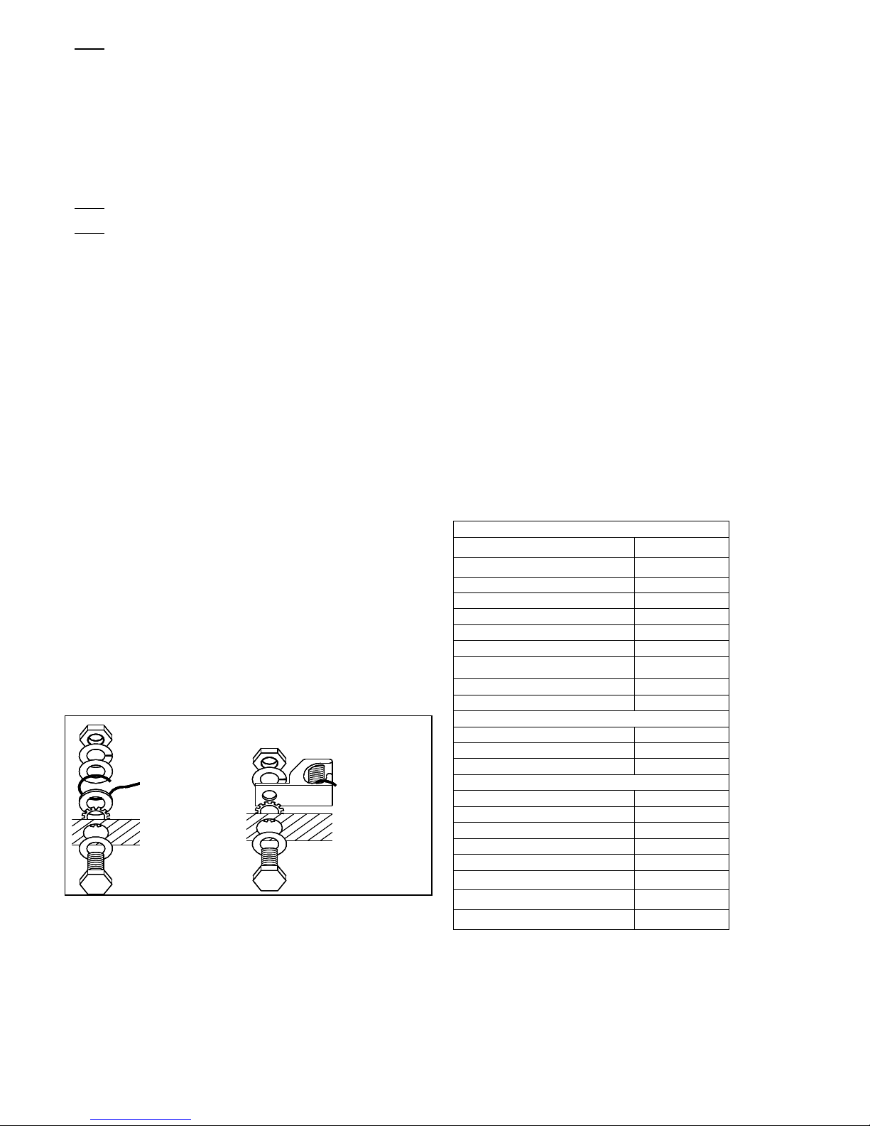
Figure 6. Inst ll tion Ex mple of Grounding
10. BLOCKING DIODES
In systems utilizing a battery, blocking diodes are ty ically laced
between the battery and PV module out ut to revent battery from
discharging at night. Kyocera PV modules are made of olycrystalline
cells with high electrical “back flow” resistance to nighttime battery
discharging. As a result, Kyocera PV modules do not contain a
blocking diode when shi ed from the factory. Most PV charge
regulators and inverter incor orate nighttime disconnect feature,
however.
11. BYPASS DIODES
Partial shading of an individual module in a source circuit string
(i.e. two
or more modules connected in series) can cause a reverse voltage
across the shaded cells within the module. Module out ut current is
then forced through the shaded area by the remaining illuminated cells
and other PV modules in series with the artially shaded module(s).
The current forced through the shaded cells within PV module (or
modules) causes additional module heating and severe loss of ower.
The ur ose of by ass diodes is to rovide a low-resistance current
ath around the shaded cells, thereby minimizing PV module heating
and array current losses.
PV modules em loy by ass diodes that have:
・ Rated Average Forward Current [I
F(AV)
] Above maximum system
current at highest PV module o erating tem erature.
・ Rated Re etitive Peak Reverse Voltage [V
RRM
] Above maximum
system voltage at lowest PV module o erating tem erature.
12. MAINTENANCE
Kyocera PV modules are designed for long life and require very little
maintenance. Under most weather conditions, normal rainfall is
sufficient to kee the module glass surface clean. If dirt build-u
becomes excessive, clean the glass surface only with a soft cloth using
mild detergent and water. USE CAUTION WHEN CLEANING THE
BACK SURFACE OF PV MODULE TO AVOID PENETRATING THE
BACK SHEET. PV modules that are mounted flat (0°tilt angle) should
be cleaned more often, as they will not "self clean" as effectively as
modules mounted at a 15°tilt or greater. Once a year, check the
tightness of terminal screws and the general condition of the wiring.
Also, check to be sure that mounting hardware is tight. Loose
connections may result in a damaged PV module or array.
13. SPECIFICATIONS
Under certain conditions, a hotovoltaic module may roduce more
voltage and current than re orted at Standard Test Conditions (STC).
Refer to Section 690 of the National Electrical Code for guidance in
series string sizing and choosing overcurrent rotection.
T ble.2 Kyocer KD Series Module Specific tion
Electric l Ch r cteristics : @ STC
Model Ty e KD135SX-UPU
Rated Power, Watts (Pmax) (W) 135 ±5%
O en Circuit Voltage (Voc) (V) 22.1
Short Circuit Current (Isc) (A) 8.37
Voltage at Load (V m) (V) 17.7
Current at Load (I m) (A) 7.63
Maximum System Voltage 600
Recommended maximum number of PV
modules connected in series 21
Factory installed By ass Diode (Qty) 8
Series Fuse Rating (A) 15
Therm l Ch r cteristics :
Tem . Coefficient of Voc (V / ℃) -0.80x10⁻¹
Tem . Coefficient of Isc (A / ℃) 5.02x10⁻³
Tem . Coefficient of V m (V / ℃) -9.20x10⁻²
Physic l Ch r cteristics :
Length, Inches (mm) 59.1 (1500)
Width, Inches (mm) 26.3 (668)
De th (frame), Inches (mm) 1.81 (46)
De th (including j-box), Inches (mm) -
Weight Pounds (kg) 27.6 (12.5)
Mounting Hole Diameter, Inches (mm) 0.35 (9) Qty-4 cs
Grounding Hole Diameter, Inches (mm) 0.35 (9) Qty-4 cs
A lication Class Class A
NOTES
(1) Standard Test Conditions of irradiance of 1000 W/m2,
s ectrum of air mass 1.5, and cell tem erature of 25 deg C.
(2) See module drawing for mounting and grounding hole
locations.
(3) Tolerance of Voc and Isc is +/-10%.
Nut
S ring washer
Flat washer
Ground conductor
Cu washer
Star washer
Aluminum frame
Flat washer
Bolt
Nut
S ring washer
Flat washer
Ground conductor
Cu washer
Star washer
Aluminum frame
Flat washer
Bolt
Nut
S ring washer
Flat washer
Star washer
Ground lug
Bolt
Aluminum
frame
Nut
S ring washer
Flat washer
Star washer
Ground lug
Bolt
Aluminum
frame
4
SECTION J-J
1.81"
0.79"
0.41"
KD135SX-UPU
"C"
"B"
"D"
"A" "H"
GR
"G"
GR
K
K
"E"
"F"
GR
J J
GR
φ
"I"
[TYP.]
GROUND HOLE
MARKED
MODULE DRAWING
JUNCTION BOX
SEE DETAILS
DIM.H
1.81"
1.18"
SECTION K-K
0.47"
0.47"
DIODE DETAIL
SYMBOL
+ -
TERMINAL DESIGNATIONS
DIODE POSTS
DO NOT USE
TYPE 'IM' J-BOX
1:NEGATIVE POST
2:POSITIVE POST
- +
1 2
DIODE(8PL)
MODULE DIMENSIONS
KD135SX-UPU
MODULE TYPE
59.1
"
DIM.A
26.3
"
DIM.B
0.49
"
DIM.D
25.3
"
DIM.C
53.5"
DIM.E
11.0
"
DIM.G
2.76
"
DIM.F
37.1
"
J-BOX TYPE
0.35
"
DIM.I
IM
KYOCERA Sol r Group S les Office
 KYOCERA Cor oration
Cor orate Solar Energy Grou
6 Takeda Tobadono-cho Fushimi-ku, Kyoto 612-8501, Ja an
Phone : 81-75-604-3476
Fax : 81-75-604-3475
htt ://www.kyocera.com/
 KYOCERA Solar, Inc.
7812 East Acoma Drive, Scottsdale, AZ 85260, U.S.A.
Phone : 1-480-948-8003 or 1-800-223-9580
Fax : 1-480-483-6431
htt ://www.kyocerasolar.com/
 KYOCERA Solar Pty Ltd.
Level 3, 6-10 Talavera Road,
North Ryde NSW 2113, Australia
Phone : 61-2-9870-3946
Fax : 61-2-9888-9673
htt ://www.kyocerasolar.com.au/
 KYOCERA Solar do Brasil Ltda.
Av. Guignard 661, Loja A
Recreio dos Bandeirantes-Rio de Janeiro, 22790-200, Brazil
Phone : 55-21-3261-7111
Fax : 55-21-3261-7103
htt ://www.kyocerasolar.com.br/
 KYOCERA Fineceramics GmbH
Fritz-Mueller-Strasse 27, 73730 Esslingen, Germany
Phone : 49-711-93934-999
Fax : 49-711-93934-950
htt ://www.kyocerasolar.de/
 KYOCERA Asia Pacific Pte. Ltd.
298 Tiong Bahru Road, #13-03/05 Central Plaza,
168730, Singa ore
Phone : 65-6271-0500
Fax : 65-6271-0600
htt ://www.kyocera.com.sg/
 KYOCERA Asia Pacific Ltd.
Room 801-802, Tower 1 , South Seas Centre,
75 Mody Road, Tsimshatsui East, Kowloon, Hong Kong
Phone : 852-2723-7183
Fax : 852-2724-4501
 KYOCERA Asia Pacific Pte. Ltd. Tai ei Branch
10 FI., No.66, Nanking West Road, Tai ei, Taiwan
Phone: 886-2-2555-3609
Fax: 886-2-2559-4131
 KYOCERA (Tianjin) Sales & Trading Cor oration
Room 2107, Ruoy chai Building,
No.8 Yong An Dong Li, Jian Guo Men Wai Road,
Chao Yang District, Beijing, 100022, China
Phone : 86-10-8528-8838
Fax : 86-10-8528-8839
htt ://www.kyocera.com.cn/
 KYOCERA Korea Co., Ltd.
Di lomatic Center Room # 406, 1376-1
Seocho-2Dong, Seocho-Ku, Seoul, 137-072,Korea
Phone: 82-2-3463-3538
Fax: 82-2-3463-3539
htt ://www.kyocera.co.kr/

Other Kyocera Solar Panel manuals

Kyocera KS12 User manual

Kyocera

Kyocera KS12 User manual

Kyocera KD135GX-LPU User manual

Kyocera

Kyocera KD135GX-LPU User manual

Kyocera KC-TYPE User manual

Kyocera

Kyocera KC-TYPE User manual

Kyocera KD205GX-LPU User manual

Kyocera

Kyocera KD205GX-LPU User manual

Kyocera KD235GX-LPB User manual

Kyocera

Kyocera KD235GX-LPB User manual

Kyocera KD210GX-LPU User manual

Kyocera

Kyocera KD210GX-LPU User manual

Kyocera MYGEN User manual

Kyocera

Kyocera MYGEN User manual

Kyocera KD130GX-LPU User manual

Kyocera

Kyocera KD130GX-LPU User manual

Kyocera KD135GX-LPU - MOUNTING GUIDE User manual

Kyocera

Kyocera KD135GX-LPU - MOUNTING GUIDE User manual

Kyocera KD 200-60 F User manual

Kyocera

Kyocera KD 200-60 F User manual

Kyocera KD215GX-LPU User manual

Kyocera

Kyocera KD215GX-LPU User manual

Kyocera KD135SX-UPU User manual

Kyocera

Kyocera KD135SX-UPU User manual

Kyocera KC85T User manual

Kyocera

Kyocera KC85T User manual

Kyocera KS10 User manual

Kyocera

Kyocera KS10 User manual

Kyocera KD225GX-LPB User manual

Kyocera

Kyocera KD225GX-LPB User manual

Kyocera KD Series Quick guide

Kyocera

Kyocera KD Series Quick guide

Kyocera KD130GX-LP User manual

Kyocera

Kyocera KD130GX-LP User manual

Kyocera KC-120-1 User manual

Kyocera

Kyocera KC-120-1 User manual

Kyocera KD185GX-LPU User manual

Kyocera

Kyocera KD185GX-LPU User manual

Kyocera KD130GX-LP User manual

Kyocera

Kyocera KD130GX-LP User manual

Kyocera KS7 User manual

Kyocera

Kyocera KS7 User manual

Kyocera KC65T User manual

Kyocera

Kyocera KC65T User manual

Kyocera KK Series Quick guide

Kyocera

Kyocera KK Series Quick guide

Kyocera OBSTRUCTION LIGHTING User manual

Kyocera

Kyocera OBSTRUCTION LIGHTING User manual

Popular Solar Panel manuals by other brands

Nice Sole KIT Instructions and warnings for installation and use

Nice

Nice Sole KIT Instructions and warnings for installation and use

REC Peak Energy BLK Series installation manual

REC

REC Peak Energy BLK Series installation manual

Topens TSP30W user manual

Topens

Topens TSP30W user manual

Unique UGP-120WSPB owner's manual

Unique

Unique UGP-120WSPB owner's manual

SW SHS050W user manual

SW

SW SHS050W user manual

Phaesun Sun Peak SPR Series Safety and installation manual

Phaesun

Phaesun Sun Peak SPR Series Safety and installation manual

RAVOLT Generation 2 Installation guidelines

RAVOLT

RAVOLT Generation 2 Installation guidelines

PowerTech ZM9137 user manual

PowerTech

PowerTech ZM9137 user manual

Jinyuan Lighting EcoMatters JY M72 Series installation instructions

Jinyuan Lighting

Jinyuan Lighting EcoMatters JY M72 Series installation instructions

Brunton SolarRoll user guide

Brunton

Brunton SolarRoll user guide

Euro-Line Solar ApolloFLEX Mono instructions

Euro-Line Solar

Euro-Line Solar ApolloFLEX Mono instructions

Nibe PV Series Installer manual

Nibe

Nibe PV Series Installer manual

PowerTech ZM9178 user manual

PowerTech

PowerTech ZM9178 user manual

Astronergy CHSM6610M installation manual

Astronergy

Astronergy CHSM6610M installation manual

Solar Flexi PV SFP010 user manual

Solar

Solar Flexi PV SFP010 user manual

GOAL ZERO Nomad 7 Plus user guide

GOAL ZERO

GOAL ZERO Nomad 7 Plus user guide

GOAL ZERO Nomad 20 user manual

GOAL ZERO

GOAL ZERO Nomad 20 user manual

Sun Power SPR-E-Flex-50 Safety and installation instructions

Sun Power

Sun Power SPR-E-Flex-50 Safety and installation instructions

manuals.online logo
manuals.online logoBrands
  • About & Mission
  • Contact us
  • Privacy Policy
  • Terms and Conditions

Copyright 2025 Manuals.Online. All Rights Reserved.