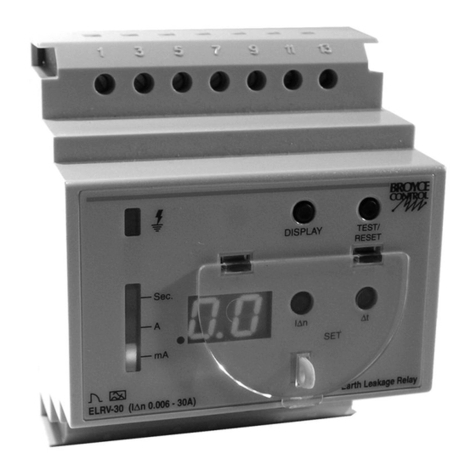
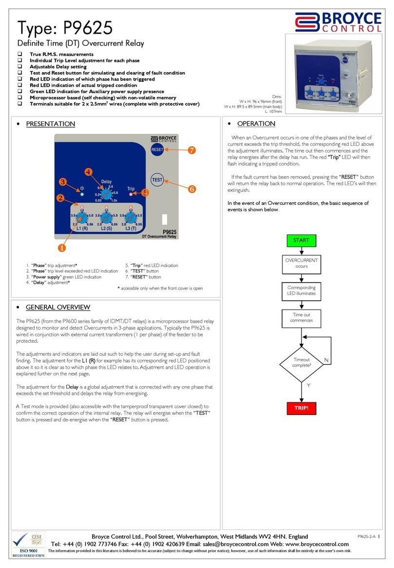
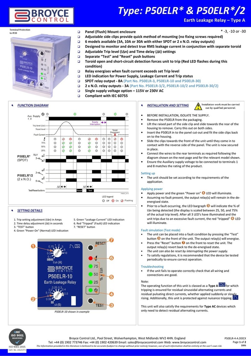
manuals.online logo
Brands
  1. Home
  2. •
  3. Brands
  4. •
  5. Broyce Control
  6. •
  7. Relay
  8. •
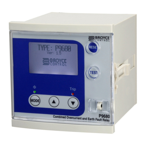
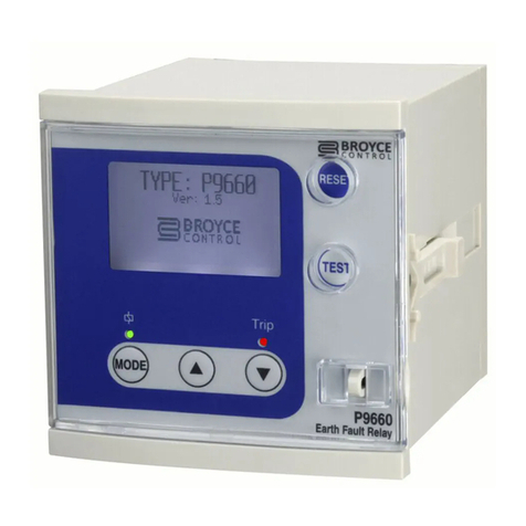
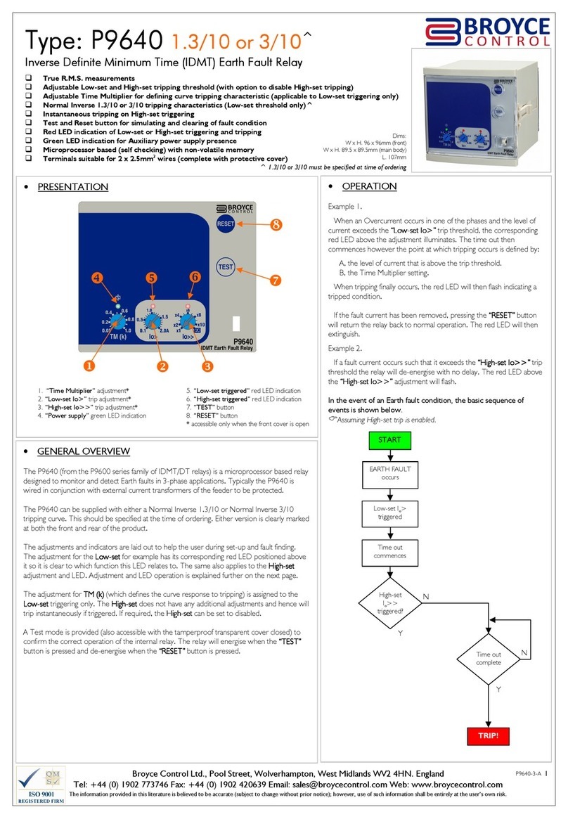
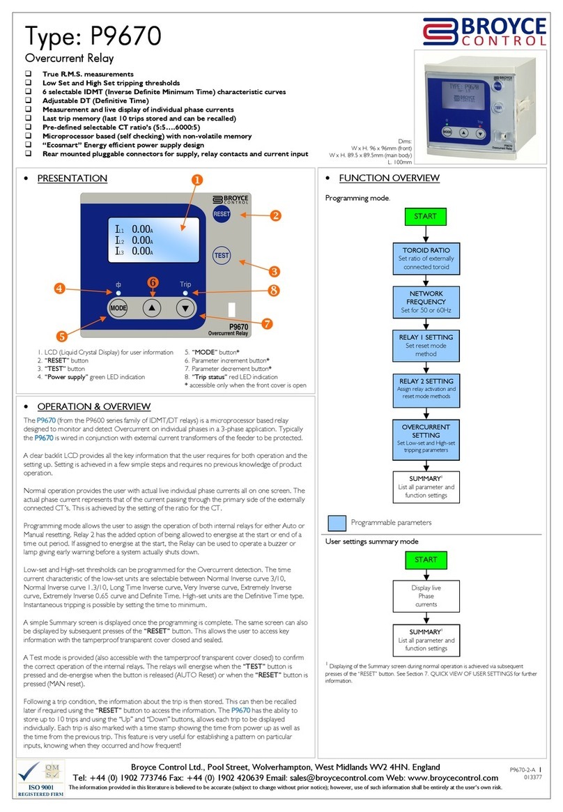
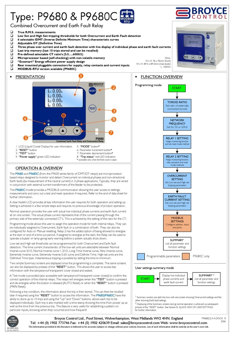
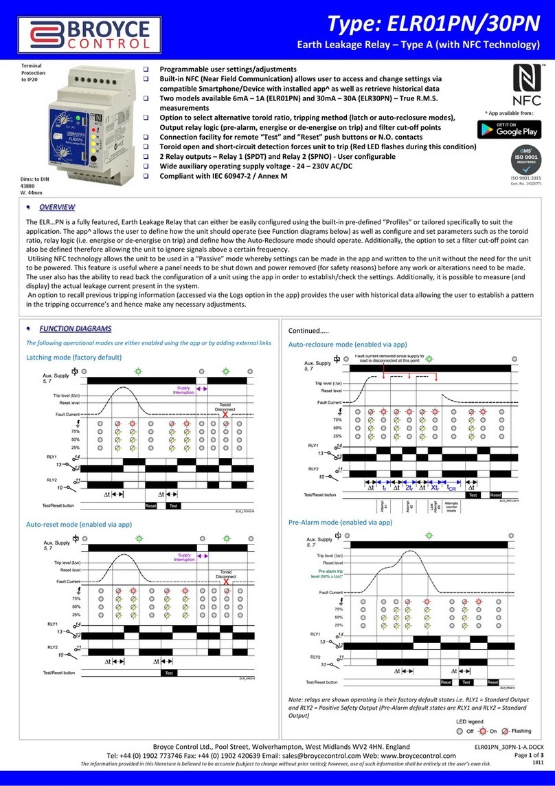
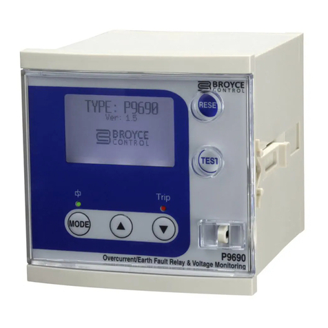
  9. Broyce Control P9600 Series User manual

Broyce Control P9600 Series User manual

Broyce Control Ltd., Pool Street, Wolverhampton, West Midlands WV2 4HN. ngland
Tel: +44 (0) 1902 773746 Fax: +44 (0) 1902 420639 mail: [email protected] Web: www.broycecontrol.com
The information provided in this literature is believed to be accurate (subject to change without prior notice); however, use of such information shall be entirely at the user’s own risk
.
P9630-2-A
1
11
1
XXXXXX
P
Type: P963
Type: P963Type: P963
Type: P9630
00
0
Inverse
Inverse Inverse
Inverse Definite Time (
Definite Time (Definite Time (
Definite Time (I
II
IDT)
DT)DT)
DT) Overcurrent
Overcurrent Overcurrent
Overcurrent Relay
Relay Relay
Relay

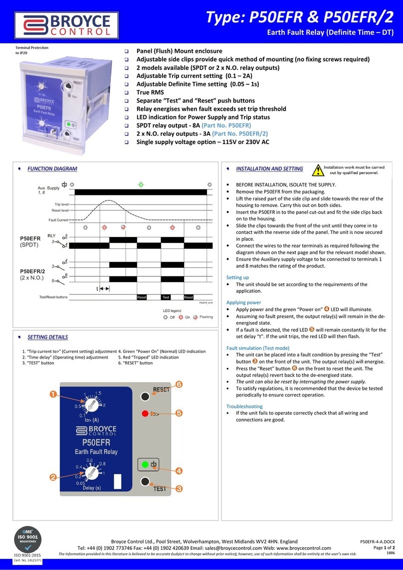
True R.M.S. measurements

Adjustable Low-set tripping threshold

Adjustable High-set tripping threshold with option to disable

Adjustable Time Multiplier for defining curve tripping characteristic applicable to Low-set triggering only)

Instantaneous tripping on High-set triggering

Test and Reset button for simulating and clearing of fault condition

Red LED indication of Low-set or High-set triggering and tripping

Green LED indication for Auxiliary power supply presence

Microprocessor based self checking) with non-volatile memory

Terminals suitable for 2 x 2.5mm
2
wires complete with protective cover)
•G N RAL OV RVI W
The P9630 (from the P9600 series family of IDMT/DT relays) is a micro rocessor based relay
designed to monitor and detect Overcurrents in 3- hase a lications. Ty ically the P9630 is
wired in conjunction with external current transformers (1 er hase) of the feeder to be
rotected.
The adjustments and indicators are laid out such to hel the user during set-u and fault
finding. The adjustment for the Low
LowLow
Low-
--
-set
setset
set for exam le has its corres onding red LED ositioned
above it so it is clear to which function this LED relates to. The same also a lies to the High
HighHigh
High-
--
-
set
setset
set adjustment and LED. Adjustment and LED o eration is ex lained further on the next age.
The adjustment for IDT
IDT IDT
IDT (which defines the curve res onse to tri ing)
is assigned to the Low
LowLow
Low-
--
-
set
setset
set triggering only. The High
HighHigh
High-
--
-set
setset
set does not have any additional adjustments and hence will tri
instantaneously if triggered. If required, the High
HighHigh
High-
--
-set
setset
set can be set to disabled.
A Test mode is rovided (also accessible with the tam er roof trans arent cover closed) to
confirm the correct o eration of the internal relay. The relay will energise when the “TEST”
“TEST”“TEST”
“TEST”
button is ressed and de-energise when the “RESET”
“RESET”“RESET”
“RESET” button is ressed.
•OP RATION
Exam le 1.
When an Overcurrent occurs in one of the hases and the level of
current exceeds the “L
“L“L
“Low
owow
ow-
--
-set
setset
set I>”
I>” I>”
I>” tri threshold, the corres onding
red LED above the adjustment illuminates. The time out then
commences however the oint at which tri ing occurs is defined by:
A, the level of current that is above the tri threshold.
B, the Time Multi lier setting.
When tri ing finally occurs, the red LED will then flash indicating a
tri ed condition.
If the fault current has been removed, ressing the “RESET”
“RESET” “RESET”
“RESET” button
will return the relay back to normal o eration. The red LED will then
extinguish.
Exam le 2.
If a fault current occurs such that it exceeds the “High
“High“High
“High-
--
-set I
set Iset I
set I>>”
>>”>>”
>>” tri
threshold the relay will de-energise with no delay. The red LED above
the “High
“High“High
“High-
--
-set I
set Iset I
set I>>”
>>”>>”
>>” adjustment will flash.
In the event of an Overcurrent condition, the basic sequence of
events is shown below.

Assuming High-set trip is enabled.
•PR S NTATION
1. “Time Multiplier” adjustment* 5. “Low-set triggered” red LED indication
2. “Low-set I>” tri adjustment* 6. “High-set triggered” red LED indication
3. “High-set I>>” tri adjustment* 7. “T ST” button
4. “Power supply” green LED indication 8. “R S T” button
* accessible only when the front cover is o en







START
OVERCURRENT
occurs
Low-set I>
triggered
Time out
commences
High-set
I>>
triggered?
N
Y
TRIP!
Timeout
com lete?
N
Y

Dims:
W x H. 96 x 96mm (front)
W x H. 89.5 x 89.5mm (main body)
L. 107mm
Broyce Control Ltd., Pool Street, Wolverhampton, West Midlands WV2 4HN. ngland
Tel: +44 (0) 1902 773746 Fax: +44 (0) 1902 420639 mail: [email protected] Web: www.broycecontrol.com
The information provided in this literature is believed to be accurate (subject to change without prior notice); however, use of such information shall be entirely at the user’s own risk
.
P9630-2-A
2
22
2
XXXXXX
P
•S TTING & OP RATION
Setting of the P9630 is carried out using the 3 otentiometers located behind the
trans arent cover.
1. IDT (k)
The adjustment for “IDT
“IDT“IDT
“IDT (k)
(k) (k)
(k)”
””
” (Time Multi lier)
defines the tri ing characteristic when the “Low
“Low“Low
“Low-
--
-set”
set”set”
set”
threshold “I>”
“I>”“I>”
“I>” has been exceeded. The lower the
setting, the faster the res onse to tri ing. The higher
the setting, the slower the res onse.
2. Low-Set Trip threshold (I>)
The adjustment for the “Low
“Low“Low
“Low-
--
-set”
set”set”
set” can be set from 2
to 6A. When the threshold is exceeded due to an
Overcurrent condition, the corres onding red LED
above the adjustment illuminates indicating activity.
When tri ing finally occurs, the red LED will then flash.
3. High-Set Trip threshold (I>>)
The adjustment for the “High
“High“High
“High-
--
-set”
set”set”
set” can be set from
x1 to x10 then disable i.e.
The scale markings are multi liers of what has been
set on the “Low
“Low“Low
“Low-
--
-set”
set”set”
set” threshold. For exam le if the
“Low
“Low“Low
“Low-
--
-set”
set”set”
set” is set to 4A and “High
“High“High
“High-
--
-set”
set”set”
set” x8, this will be the
equivalent of 4 x 8 = 32A.
When the threshold is exceeded due to an
Overcurrent condition, the corres onding red LED
above the adjustment illuminates indicating activity.
When tri ing finally occurs, the red LED will then flash.

If tripping occurs whereby the High-set level is exceeded, only the LE for the
High-set will illuminate/flash. This allows the user to clearly identify which threshold
was triggered causing the trip.

There is no delay associated with High-set therefore, tripping is instantaneous.
•L D FUNCTION SUMMARY

The green LE will remain illuminated for as long as power is applied to the Aux.
connections (Terminals 1 and 2).
In res onse to an Overcurrent condition:
Status I> I>>
Normal
Low-set triggered
Low-set Tri ed
High-set triggered
High-set Tri ed
In res onse to Test and Reset button o eration:
Button press I> I>>
Key:
LED off
LED on
LED flashing
•INSTALLATION
•B FOR INSTALLATION, ISOLAT TH SUPPLY. THIS PRODUCT IS
D SIGN D TO CONN CT TO S V RAL TYP S OF CIRCUITS.
NSUR ALL AR ISOLAT D
•Remove the P9630 from the ackaging.
•Lift the raised art of the side cli in order to remove from the housing. Carry
this out on each side.
•Insert the P9630 into the anel cut-out and fit the side cli s back on to the
housing.
•Slide the cli s towards the front of the unit until they come in to contact with
the reverse of the anel. The unit is now secured in lace.
•Connect wires to the rear terminals as required.
•The P9630 is now ready for owering and setting.

The front window of the P9630 is supplied with a clear protective film which can be
removed as and when necessary.
•NORMAL OP RATION
•A ly ower to the unit and the green “Power su ly”
“Power su ly”“Power su ly”
“Power su ly” LED will illuminate.
•T ST MOD
•Press and hold the button and the relay will energise. Both the red “I>”
“I>”“I>”
“I>”
and “I>>”
“I>>” “I>>”
“I>>” LED’s will illuminate.
•Release the button and the relay will remain energised.
•Press the button to de-energise the relay. Both red LED’s will
extinguish.

Testing should be carried out on a regular basis to check the integrity of the
P9630.
O NOT use this product to provide a means of isolating circuits in
order to work on when placed in the “TEST”
“TEST”“TEST”
“TEST” mode. This should only be
done by means of operating isolators, circuit breakers or other
methods of removing power in this application.
Installation work must be carried
out by qualified personnel.
Broyce Control Ltd., Pool Street, Wolverhampton, West Midlands WV2 4HN. ngland
Tel: +44 (0) 1902 773746 Fax: +44 (0) 1902 420639 mail: [email protected] Web: www.broycecontrol.com
The information provided in this literature is believed to be accurate (subject to change without prior notice); however, use of such information shall be entirely at the user’s own risk
.
P9630-2-A
3
33
3
XXXXXX
P
Housing:
Flame retardant Lexan
Protection: IP55 / IP20 (rear)
Weight: ≈ 590g
Mounting: Panel mounting. Cut-out = 91 x 91mm (± 0.5mm)
Max. anel thickness: 12mm
Terminal conductor size: 0.05 - 2.5mm
2
(30 - 12AWG)
Recommended tightening
torque: 10in lb (1Nm)
Wire stri ing length: 0.24 – 0.30in (6 – 7.5mm)
A rovals: Conforms to IEC. CE and and RoHS Com liant.
EMC: Immunity: EN/IEC 61000-6-2
Emissions: EN/IEC 61000-6-4
Generic: IEC 60255-26 (EMC), IEC 255-3, IEC
60255-151
( ) Bold digits in brackets refer to terminal numbers on the rear of the unit.
Options:
The P9600 range also includes individual Overcurrent or Earth fault relays
available with either IDT or IDMT tri ing characteristics. Please refer to se arate
data sheets.
Tripping Curve Characteristics.
•T CHNICAL SP CIFICATION
Su ly voltage Un (1, 2): 115VAC ±15%
230VAC ±15%
(Voltage should be specified at time of ordering)
Rated frequency: 50/60Hz
Isolation: Over voltage cat. III
Rated im ulse
withstand voltage: 4kV (1.2 / 50µS) IEC 60664
Power consum tion: 3W max.
Rated current in ut In: 5A (directly connected)
Rated frequency: 50Hz
Burden: <0.4VA @ In
Overload: 4 x In (continuous)
External CT’s
(9, 10, 11, 12, 13, 14): Class P recommended. (with 5A secondary)
Overcurrent settings:
Low-set tri (I>): 2.0 – 6.0A (40 – 120%)
Time multi lier (IDT): 0.05 – 1.0
High-set tri (I>>): x1 – x10 or disable ( )
High-set definite time: Instantaneous (<50mS)
Pick u value: +2% of tri setting
Accuracy:
Protection thresholds: ± 5%
Res onse time: ± 5% (with a minimum of 50mS)
Re eat accuracy: ± 0.5% @ constant conditions
Ambient tem erature: -10 to +60°C
Relative humidity: +95% (non-condensing)
Out ut:
(RL1 - 3, 4, 5): 1 x SPDT relay
Out ut rating: AC1 250V 8A (2000VA)
AC15 250V 5A (1250VA)
DC1 25V 8A (200W)
Electrical life: ≥ 150,000 o s at rated load
Dielectric voltage: 2kV AC (rms) IEC 60947-1
Rated im ulse
withstand voltage: 4kV (1.2 / 50µS) IEC 60664
Max. DC Load Breaking Ca acity Electrical Endurance
•CONN CTION DIAGRAM
L1
L2
L3
N
A1
A2
RL1
Aux.
911
10
12
13
14
15
16
1
3
2
4
5
6
7
8
I
L1
I
L2
I
L3
•DIM NSIONS
96
96
10
95
89.5
96
12
80
Front view Side view
All dimensions are in mm.
t
t
t
t
(s)
(s)
(s)
(s)
10
1
0.1
k
kk
k
1.0
0.9
0.8
0.7
0.6
0.5
0.4
0.3
0.2
0.1
1 10 20
I/I>
I/I>I/I>
I/I>

This manual suits for next models

1

Other Broyce Control Relay manuals

Broyce Control P50EFR User manual

Broyce Control

Broyce Control P50EFR User manual

Broyce Control P9625 User manual

Broyce Control

Broyce Control P9625 User manual

Broyce Control ELR01PN User manual

Broyce Control

Broyce Control ELR01PN User manual

Broyce Control ELRV-30 User manual

Broyce Control

Broyce Control ELRV-30 User manual

Broyce Control ELRV-30 User manual

Broyce Control

Broyce Control ELRV-30 User manual

Broyce Control P9650 User manual

Broyce Control

Broyce Control P9650 User manual

Broyce Control P9680 User manual

Broyce Control

Broyce Control P9680 User manual

Broyce Control EcoSmart P9670 User manual

Broyce Control

Broyce Control EcoSmart P9670 User manual

Broyce Control P50ELR Series User manual

Broyce Control

Broyce Control P50ELR Series User manual

Broyce Control P9660 User manual

Broyce Control

Broyce Control P9660 User manual

Broyce Control P9640 User manual

Broyce Control

Broyce Control P9640 User manual

Broyce Control P9620 User manual

Broyce Control

Broyce Control P9620 User manual

Broyce Control P9680C User manual

Broyce Control

Broyce Control P9680C User manual

Broyce Control P9690 User manual

Broyce Control

Broyce Control P9690 User manual

Popular Relay manuals by other brands

F&F BIS-419-LED quick start guide

F&F

F&F BIS-419-LED quick start guide

Schweitzer Engineering Laboratories SEL-787 instruction manual

Schweitzer Engineering Laboratories

Schweitzer Engineering Laboratories SEL-787 instruction manual

Pilz PNOZ X3.2 operating manual

Pilz

Pilz PNOZ X3.2 operating manual

Mikro DIN310 user manual

Mikro

Mikro DIN310 user manual

Seg HighTECH MRR1 manual

Seg

Seg HighTECH MRR1 manual

ABB Relion 615 series installation manual

ABB

ABB Relion 615 series installation manual

Thytronic NA011 manual

Thytronic

Thytronic NA011 manual

GE F60 instruction manual

GE

GE F60 instruction manual

Omron K8AB-VS Series quick start guide

Omron

Omron K8AB-VS Series quick start guide

Astrel Group rialto installation manual

Astrel Group

Astrel Group rialto installation manual

SLV SLV CONTROL 470806 Quick installation guide

SLV

SLV SLV CONTROL 470806 Quick installation guide

ABB SPAM 150 C technical information

ABB

ABB SPAM 150 C technical information

NR Electric PCS-9611 instruction manual

NR Electric

NR Electric PCS-9611 instruction manual

BrickElectric BEM104 manual

BrickElectric

BrickElectric BEM104 manual

Eurotherm TE200S user manual

Eurotherm

Eurotherm TE200S user manual

DLI DIN4 user guide

DLI

DLI DIN4 user guide

Mart BR-11 user manual

Mart

Mart BR-11 user manual

GE CEY52B instructions

GE

GE CEY52B instructions

manuals.online logo
manuals.online logoBrands
  • About & Mission
  • Contact us
  • Privacy Policy
  • Terms and Conditions

Copyright 2025 Manuals.Online. All Rights Reserved.