1. Safety Warnings
This instrument has been designed, manufactured and
testedaccordingtothefollowingstandards.
IEC
61010
-
1
MeasurementCAT
Ⅲ
300
VPollutiondegree
2
IEC
61010
-
031
IEC
61326
This instruction manual contains warnings and safety
rules which must be observed by the user to ensure
safe operation of the instrument and retain it in safe
condition.Therefore,readthroughtheseoperating
instructionsbeforeusingtheinstrument.
#
WARNING
●
Readthroughandunderstandinstructionscontained
inthismanualbeforestartingusingtheinstrument.
●
Save and keep the manual handy to enable quick
referencewhenevernecessary.
●
Thisinstrumentshouldonlybeusedbysuitably
trained person and be sure to follow measurement
proceduresdescribedinthemanual.Kyoritsu
assumes no responsibility for damage and injury
causedbymisuseornotfollowinginstructionsinthe
manual.
●
Besuretounderstandandfollowallsafety
instructionscontainedinthemanual.
Besuretoobservetheaboveinstructions.
Failure to follow the above instructions may cause
injury,instrumentdamageand/ordamagetoequipment
undertest.
The symbol
#
indicated on the instrument means that
theusermust refertorelated partsinthemanualfor safe
operationoftheinstrument.
Besuretocarefullyreadtheinstructionsfollowing
#
each
symbolinthemanual.
#
DANGER
isreservedforconditionsandactionsthat
arelikelytocauseseriousorfatalinjury.
#
WARNING
is reserved for conditions and actions
thatcancauseseriousorfatalinjury.
#
CAUTION
isreservedforconditionsandactionsthat
cancauseinjuryorinstrumentdamage.
#
DANGER
●
Nevermakemeasurementonthecircuitinwhichelectrical
potentialtogroundover
300
VAC/DCexists.
●
Donotattempttomakemeasurementinthepresenceof
flammablegasses.Otherwise,theuseoftheinstrument
maycausesparking,whichcanleadtoanexplosion.
●
BesuretokeepyourfingersbehindtheFingerbarrier
partoftestlead.
●
Never attempt to use the instrument if its surface or
yourhandiswet.
●
Donotopentheinstrumentcasewhenmaking
measurement.
#
WARNING
●
Neverattempttomakeanymeasurementifany
abnormalconditions are noted, such asbrokencase,
crackedtestleadsandexposedmetalparts.
●
Donotturnthefunctionselectorswitchwithtest
leadsconnectedtotheinstrument.
●
Donotinstallsubstitutepartsormakeany
modificationtotheinstrument.
●
Donottrytoreplacethebatteriesifthesurfaceofthe
instrumentiswet.
●
Make sure to disconnect test leads from the device
undertestwhenopeningthecaseforbattery
replacement.
●
UseofourProtectiveCapoffersdifferentlengthsofthe
exposedmetalpartsuitableforthetestenvironments.
PleaseattachtheCapontothemetalpartunderCAT.
IIIorhighertestenvironments.
#
CAUTION
●
AlwaysmakesuretocheckFunctionswitchissetting
totheappropriaterangebeforestartingmeasurement.
●
Donotexposetheinstrumenttothedirectsun,high
temperatureandhumidityordewfall.
●
When the instrument will note be in use for a long
period,placeitinstorageafterremovingthebatteries.
●
Useaclothdippedinwaterorneutraldetergentfor
cleaningtheinstrument.Donotuseabrasivesorsolvents.
●
TheCapshouldbefirmlyattachedtotheProbes.
Pleaserefertofollowing explanationofthe symbols
markedontheinstrumentorinthemanual.
●
Symbols
:
Ground
:
AC
:
DC
:
ACandDC
Ω
:
Resistance
:
Diode
:
Buzzer
:
Capacitor
Hz
:
Frequency
:
Doubleorreinforcedinsulation
●
Measurement
CAT
Ⅱ:
Primaryelectricalcircuitof equipmentwith
powercordforconnectiontooutlet.
CAT
Ⅲ:
Primaryelectricalcircuitofthe
equipment, which is supplied power from
a distribution board, and cable run from a
distributionboardtoanoutlet.
2. Features
Thisisa DigitalMulti Meterprovidingmostportability
bymeansofstowingtheinstrumentbodytogetherwith
probeinthenotebook-sizecover.
●
Designedtointernationalsafetystandards.
IEC
61010
-
1
MeasurementCAT.
Ⅲ
300
V
Pollutiondegree
2
IEC
61010
-
031
(probeassemblies)
●
REL function to check the difference of measured
values
●
Autopowerofffunctiontosavebatteryconsumption
●
Dataholdfunction
●
DiodeandContinuitycheckfunction
●
Auto-rangingfunction
●
Frequencymeasurementfunction
●
DUTYmeasurementfunction
(ExpressPulsewidth/Pulseperiodasa
percentage)
3. Specification
●
Measuringrangesandaccuracy
(
23
±
5
℃
,underthe
45
%
〜
75
%RH)
DCVFunction(
5
Autoranging):Inputimpedanceapprox.
10
M
Ω
Range Measuringrange Accuracy
400
mV
0
〜
600
V
±
0
.
8
%rdg
±
5
dgt
4
V
40
V
400
V
600
V
±
1
.
0
%rdg
±
5
dgt
ACVFunction(
4
Autoranging):Inputimpedanceapprox.
10
M
Ω
Range Measuringrange Accuracy
4
V
0
〜
600
V
±
1
.
3
%rdg
±
5
dgt(
50
/
60
Hz)
±
1
.
7
%rdg
±
5
dgt(
〜
400
Hz)
40
V
400
V
±
1
.
6
%rdg
±
5
dgt(
50
/
60
Hz)
±
2
.
0
%rdg
±
5
dgt(
〜
400
Hz)
600
V
ResistanceFunction(
6
Autoranging)
Range Measuringrange Accuracy
400
Ω
0
〜
40
M
Ω ±
1
.
0
%rdg
±
5
dgt
4
k
Ω
40
k
Ω
400
k
Ω
4
M
Ω
40
M
Ω ±
2
.
5
%rdg
±
5
dgt
Diodecheck/ContinuitycheckFunction
Function Measuringrange
Diodecheck Testcurrentapprox.
0
.
4
mA
Continuitycheck Buzzerbeepsbelowabout
120
Ω
CapacityFunction(
6
Autoranging)
Range Measuringrange Accuracy
4
nF
〜
200
uF
±
5
.
5
%rdg
±
10
dgt
40
nF
±
3
.
5
%rdg
±
10
dgt
400
nF
±
3
.
5
%rdg
±
5
dgt
4
uF
40
uF
200
uF
±
4
.
5
%rdg
±
5
dgt
Frequency(
4
Autoranging)/DUTYFunction
Range Measuringrange Accuracy
10
Hz
〜
10
kHz
Inputsensitivity:
morethan
1
.
5
V(RMS)
±
0
.
1
%rdg
±
5
dgt
100
Hz
1000
Hz
10
kHz
DUTY
0
.
1
〜
99
.
9
%
(Pulsewidth/Pulseperiod)
±
2
.
5
%rdg
±
5
dgt
Note:
*AtVoltagefunction,theAuto-rangingfunctionisreleased
bypressingtheSELECTkey.Tomeasureavoltageagain,
turntheFunctionswitchtothe"OFF"positiononce.Then
setittotheVoltagefunctionagain.
● Standards :
IEC
61010
-
1
MeasurementCAT
Ⅲ
300
V,pollutiondegree
2
IEC
61010
-
031
cappedconditionforCAT.III
300
V
uncappedconditionforCAT.II
300
V
IEC
61326
● Method of operation : △
∑method
● Indication:
LCDmaximumvalue
3999
(ACV,DCV,
Ω
,F)
units,symbols
● Over range display :
"OL"symbolisdisplayedontheLCD.
In case that the value is beyond effective measuring
range at the position of
Ω
function range and manual
range.
● Auto-ranging :
Range shifts to upper range when indicated value is
morethan
3999
.Rangeshiftstolowerrangewhen
indicatedvalueislessthan
360
.
● Sampling rate :
approx.
400
ms
● Operating Environmental conditions
−
indooruse
−
altitudeupto
2000
m
●
Temperature & Humidity range(guaranteed accuracy):
23
℃±
5
℃
Relativehumidity:lessthan
75
%
● Operating Temperature & Humidity range:
0
℃〜
+
40
℃
Relativehumidity:lessthan
80
%
● Storage Temperature & Humidity range:
-
20
℃〜
+
60
℃
Relativehumidity:lessthan
70
%
● Insulation Resistance:
Itshouldbemorethan
10
M
Ω
/DC
1000
Vbetween
electricalcircuitandenclosures.
● Withstand Voltage :
ItshouldbemorethanAC
3700
V/foroneminute
betweenelectricalcircuitandenclosures.
● Overload Protection :
Voltagefunction:
720
V(RMS.)
10
seconds
Resistancefunction:
250
V(RMS.)
10
seconds
Diode/Continuity:
250
V(RMS.)
10
seconds
Capacityfunction:
250
V(RMS.)
10
seconds
Frequencyfunction:
250
V(RMS.)
10
seconds
● Dimensions :
approx.
107
(L)x
54
(W)x
10
(D)mm
● Weight :
approx.
70
g(includingbatteries)
● Power source :
TwoLR
44
(SR
44
)
1
.
5
Vorequivalent
● Accessories :
TwoLR
44
(SR
44
)batteries
Portableholder
Instructionmanual
#
CAUTION
The voltage shown above is the overload protection
(overvoltageprotection)fortheinstrument.
Makesurenottoexceedthevalueofvoltageshown
above.
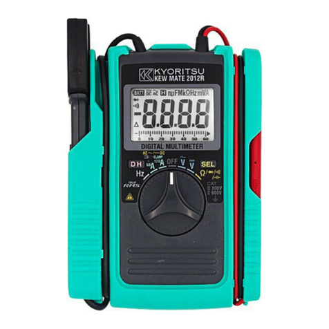
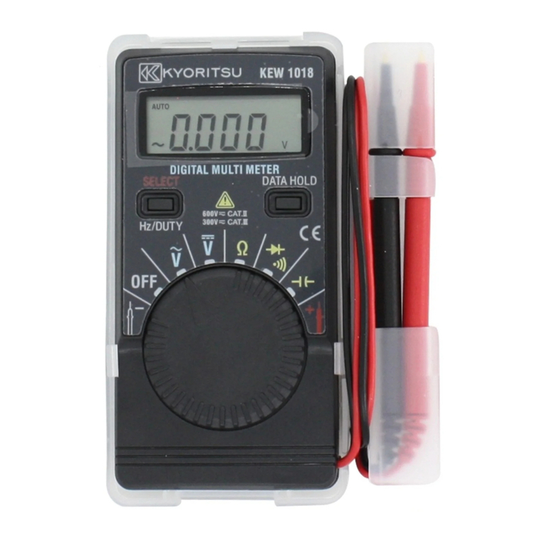
4. Instrument Layout
①
FunctionSelectorSwitch
④
DATAHOLDKey
②
Display
⑤
TestLeads
③
SELECTKey
5. Preparation
5
-
1
CheckingBatteryVoltage
Set the Function Selector Switch to other positions
excepttheOFFposition.
Battery Voltage is enough if indication is clear and
BTsymbolisnotindicatedinthisbout.
IfBTsymbolisindicatedornoindicationonthe
display,followtotheBatteryReplacementprocedures
showninitem
9
inthisdocumentandreplacewithnew
batteries.
INSTRUCTION MANUAL
6. Measurements
6-1VoltageMeasurement(DCV,ACV)
#
DANGER
●
Toavoidthedangerofgettingelectricalshock,
nevermakemeasurement ona circuitover
600
V
AC/DC.(electricalpotentialtoground
300
VAC/DC)
●
DonotoperateFunctionSelectorSwitchduring
measurement.
●
Donotmakemeasurementwhenopeningthe
instrumentcase.
6
-
1
-
1
DCVoltageMeasurement(DCV)
(
1
)SettheFunctionSelectorSwitchto" "position.
(Then, "AUTO"," "and"mV" symbols are indicated
onthedisplay.)
(
2
)Connect the black test lead to the negative side of
thecircuitunderthetestandtheredtestleadtothe
positiveside of thecircuit,then the measured value
is indicated on the display. If you connect the test
leads the other way, "
-
" symbol is indicated on the
display.
6
-
1
-
2
ACVoltageMeasurement(ACV)
(
1
)SettheFunctionSelectorSwitchto" "position.
(Then,"AUTO","
",and"V"symbolsareindicated
onthedisplay.)
(
2
)Connectthetestleadstothecircuitundertest.
Measuredvalueisindicatedonthedisplay.
Note)Even if short-circuit the input line at the range of
AC
4
V,
2
〜
5
dgtmayremainindicated.
6-2ResistanceMeasurement
#
DANGER
●
To avoidthedangerofgettingelectricalshock,
never make measurement of the circuit in which
electricpotentialexists.
●
Donotmakemeasurementwhenopeningthe
instrumentcase.
(
1
)SettheFunctionSelectorSwitchto"
Ω
"position.
(Then,"AUTO"and"M
Ω
"symbolsareindicated
onthedisplay.)Makesurethatthe"OL"symbol
is indicated on the display at this bout, then short
thetest lead tips and check "
0
"is indicated on the
display.
(
2
)Connectthetestleadstobothendsoftheresistance
undertest.
Measuredvalueisindicatedonthedisplay.
Note)Evenifshort thetestlead tips,indicatedvalue may
notbe "
0
".But this is because of the resistance of
testleadsandnotafailure.
6-3ContinuityCheck/DiodeCheck
#
DANGER
●
To avoidthedangerofgettingelectricalshock,
never make measurement of the circuit in which
electricpotentialexists.
●
Donotmakemeasurementwhenopeningthe
instrumentcase.
6
-
3
-
1
ContinuityCheck
(
1
)
SettheFunctionSelectorSwitchto"
/ "position.
(Then, " " and
Ω
symbols are indicated on the
display.)
(
2
)Make sure that the "OL" symbol is indicated on the
displayatthisbout,thenshortthetestleadtipsand
check"
0
"isindicatedonthedisplayandcheckifthe
buzzerbeeps.
(
3
)Connectthetestleadstobothendsoftheresistance
undertest.
Measuredvalueisindicatedonthedisplay.The
buzzerbeepsbelowabout
120
Ω
.
Note)Evenifshortthetestlead tips,indicatedvalue may
notbe "
0
".But this is because of the resistance of
testleadsandnotafailure.
6
-
3
-
2
DiodeCheck
(
1
)
SettheFunctionSelectorSwitchto"
/ "position.
(Then, " " and "
Ω
" symbols are indicated on the
display.)
(
2
)PresstheSELECTKeytwiceandsettheinstrument
toDiode Check mode.(Then,"
"and "V" symbols
are indicated on the display.) Make sure that the
"OL"symbolisindicatedonthedisplayatthis
bout, then short the test lead tips and check "
0
" is
indicatedonthedisplay.
(
3
)Connect the black test lead to the cathode side of
theDiodeandtheredtestleadtotheanodesideof
theDiode.
ForwardvoltageofDiodeisindicatedonthedisplay.
(
4
)Connecttheblacktestleadtotheanodesideofthe
Diode and the red test lead to the cathode side of
theDiode.Normally, "OL" symbol is indicated on the
display.
Conclusion:Diode is OK if the instrument complies with
aboveitems(
3
)and(
4
).
Note)Open-circuitvoltagebetweenmeasuringterminalsis
approx.
1
.
5
V.(measuringcurrentapprox.
0
.
4
mA)
6-4CapacitanceMeasurement
#
DANGER
●
To avoidthedangerofgettingelectricalshock,
never make measurement of the circuit in which
electricpotentialexists.
●
Donotmakemeasurementwhenopeningthe
instrumentcase.
●
Makesuretodischargethecapacitorbeforemaking
measurement.
(
1
)SettheFunctionSelectorSwitchto" "position.
(Then, "AUTO" and "nF" symbols are indicated on
thedisplay.)
(
2
)PresstheSELECTkeyand"
0
"shallbeindicated.
(Then,"
△
"symbolisindicatedonthedisplay.)
(
3
)Connectthetestleadstobothendsoftheresistance
undertest.
Measuredvalueisindicatedonthedisplay.
Measuring unit "nF" / "uF" is automatically chosen
andindicatedduetothemeasuredvalue.
Note)It may take some time according to the measuring
capacitance.
Measuringcapacitance <
4
uFMeasuringtime is
about
2
seconds
Measuring capacitance <
40
uF Measuring time is
about
7
seconds
Measuring capacitance <
100
uF Measuring time is
about
15
seconds
6-5FrequencyMeasurement
#
DANGER
●
To avoid the danger of getting electrical shocks,
nevermakemeasurement ona circuitover
300
V
AC/DC.(electricalpotentialtoground
300
VAC/DC)
●
DonotoperateFunctionSelectorSwitchduring
measurement.
●
Donotmakemeasurementwhenopeningthe
instrumentcase.
FrequencycanbemeasuredatACVfunctionsby
pressing"Hz/DUTY"Switch.Concerningwiththe
directionforuseof"Hz/DUTY"Switch,please
referencetotheitem
7
-
1
Hz/DUTYinthisdocument.
Note)
Theminimuminputcanbemeasuredisapprox.
1
.
5
V.
Tomeasureafrequency,measure thevoltageonthe
electrical circuit in advance. Then press the "Hz/
DUTY"Keytoenterintofrequencymeasurement.
Readingsoffrequencymayfluctuateorbe
influencedundernoisyenvironment.
7. How to use Function Switches
7-1SELECT,Hz/DUTYKey
Ateachfunction,theactionsofSELECT,Hz/DUTYkey
aredifferentsopleaserefertofollowingitemsandmake
activeuseofthem.
●
ACVfunction
(AbovetwokeysactasHz/DUTYswitchkey.)
CapableofselectingtheVoltage,Frequencyor
DUTYmeasurementmode.
At the initial condition, Voltage measurement has
beenselectedfortheACVfunction.
Bypressing"Hz/DUTY"key,measuringmode
changes.
"Voltage"
→
"Frequency"
→
"DUTY"
●
*
AtVoltagefunction,theAuto-rangingfunctionis
released by pressing the SELECT key. To measure a
voltage again, turn the Function switch to the "OFF"
positiononce.ThensetittotheVoltagefunctionagain.
●
DCV,
Ω
andCapacitancemeasurement
(AbovetwokeysactasREL
△
key.)
Indicatethedifferencebetweenmeasuredvalues.
When any function ("DCV", "
Ω
" and "Capacitance")
selected,themeasuredvaluecanbestoredby
pressing SELECT key and after that, the difference
betweenstored value andmeasuringvalueis
indicatedonthedisplay
(
△
markiskeep lightingonthedisplaywhileavalue
isstored)
Thestoredvaluecanbereleasedbypressing
"SELECT"keyagain.
"Release"
→
"Memory"
●
Continuitycheck/Diodecheckfunction
(ChangebetweenContinuitycheckandDiodecheck)
Attheinitial condition, "Continuity check" mode has
beenselectedfortheContinuitycheck/Diodecheck
function.
Bypressing"SELECT"key,measuringmode
changes.
"Continuitycheck"
→
"Diodecheck"
Therelativemeasurement isallowed inthefollowing
range.
*Measuring range = Full scale value at a range
−
initialvalue
7-2DATAHOLDKey
Themeasuredvaluecanbeholdatallfunctions.
By pressing "DATA HOLD" key, "DH" symbolindicated
onthedisplayandtheindicatedvaluecanbeheld.
Bypressing"DATAHOLD"keyagain,"DH"symbol
disappearsfromthedisplayandhelddataisreleased.
8. Auto Power Off
Autopowerofffunctionoperateswhenabout
15
minutes
passedafterpoweronthisinstrument.WhenAuto
powerofffunctionoperatesandtheinstrumentpowered
off, the power-off statue returns to normal by pressing
anykey.
9. Battery Replacement
#
DANGER
●
Neveropentheinstrumentcasewhenmaking
measurement.
●
Toavoidgettingelectricalshock,besuretoremove
test leads from the instrument when opening the
instrumentcaseinordertoreplacebatteries.
(
1
)RemovethePortableholderfromtheinstrument.
(
2
)Loosen one screw on the bottom of the instrument
andopenthebatterycover,thenreplacebatteries.
Battery:TwoLR
44
(SR
44
)
1
.
5
Vorequivalent
10. Maintenance
Use a cloth dipped in water or neutral detergent for
cleaningtheinstrument.Donotuseabrasivesor
solvents.
DISTRIBUTOR
Kyoritsureservestherightstochangespecifications
or Designs described in this manual without notice
andwithoutobligations.
CARD TYPE AUTO RANGE DIGITAL MULTIMETER
KEW 1018
