manuals.online logo
Brands
  1. Home
  2. •
  3. Brands
  4. •
  5. Kyosho
  6. •
  7. Motorized Toy Car
  8. •
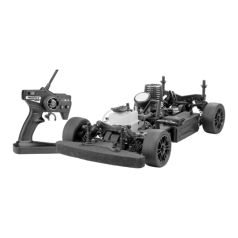
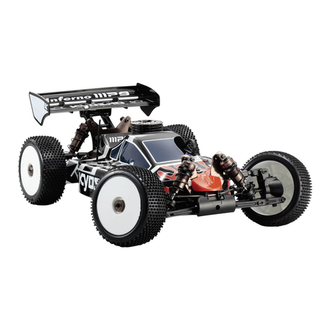
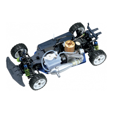
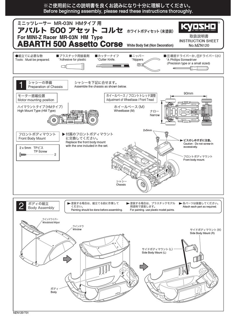
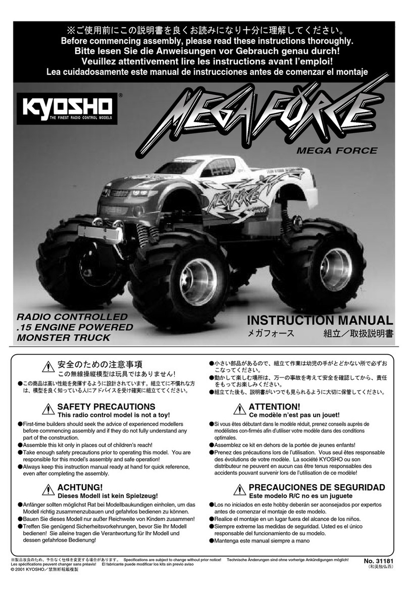
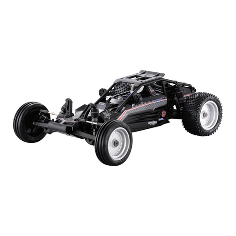
  9. Kyosho Presto User manual

Kyosho Presto User manual

This manual suits for next models

1

Other Kyosho Motorized Toy Car manuals

Kyosho Inferno GT2 ReadySet User manual

Kyosho

Kyosho Inferno GT2 ReadySet User manual

Kyosho MINI-Z Racer MR-03 User manual

Kyosho

Kyosho MINI-Z Racer MR-03 User manual

Kyosho EP FAZER Dirt Hog User manual

Kyosho

Kyosho EP FAZER Dirt Hog User manual

Kyosho MAD FORCE KRUISER 2.0 VE User manual

Kyosho

Kyosho MAD FORCE KRUISER 2.0 VE User manual

Kyosho CUP Series User manual

Kyosho

Kyosho CUP Series User manual

Kyosho Javelin 4WD User manual

Kyosho

Kyosho Javelin 4WD User manual

Kyosho EP ULTIMA RB Type-R User manual

Kyosho

Kyosho EP ULTIMA RB Type-R User manual

Kyosho INFERNO MP7.5 Sports2 readyset User manual

Kyosho

Kyosho INFERNO MP7.5 Sports2 readyset User manual

Kyosho Mini-Z Racer MR-02 MM Type User manual

Kyosho

Kyosho Mini-Z Racer MR-02 MM Type User manual

Kyosho PureTen GP Alpha 2 4WD SERIES User manual

Kyosho

Kyosho PureTen GP Alpha 2 4WD SERIES User manual

Kyosho INFERNO ST-R User manual

Kyosho

Kyosho INFERNO ST-R User manual

Kyosho RAGE VE User manual

Kyosho

Kyosho RAGE VE User manual

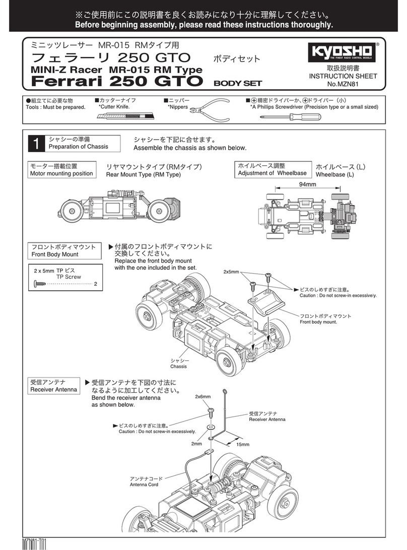
Kyosho MINI-Z Racer MR-015 RM Type User manual

Kyosho

Kyosho MINI-Z Racer MR-015 RM Type User manual

Kyosho INFERNO MP7.5 Sports 3 readyset User manual

Kyosho

Kyosho INFERNO MP7.5 Sports 3 readyset User manual

Kyosho TF7 User manual

Kyosho

Kyosho TF7 User manual

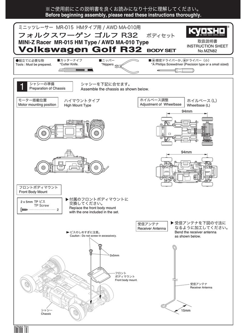
Kyosho MINI-Z Racer AWD MA-010 Type User manual

Kyosho

Kyosho MINI-Z Racer AWD MA-010 Type User manual

Kyosho Inferno ST-RR User manual

Kyosho

Kyosho Inferno ST-RR User manual

Kyosho Fazer VE User manual

Kyosho

Kyosho Fazer VE User manual

Kyosho MINI-Z RACER User manual

Kyosho

Kyosho MINI-Z RACER User manual

Kyosho Mini-Z Racer MR-02 MM Type User manual

Kyosho

Kyosho Mini-Z Racer MR-02 MM Type User manual

Kyosho SCORPION XXL VE User manual

Kyosho

Kyosho SCORPION XXL VE User manual

Kyosho MINI-Z Racer MR-015 RML Type User manual

Kyosho

Kyosho MINI-Z Racer MR-015 RML Type User manual

Kyosho MINI-Z Racer MR-02 RM Type User manual

Kyosho

Kyosho MINI-Z Racer MR-02 RM Type User manual

Kyosho FX-101 Series User manual

Kyosho

Kyosho FX-101 Series User manual

Popular Motorized Toy Car manuals by other brands

Reely Dune Fighter 3S operating instructions

Reely

Reely Dune Fighter 3S operating instructions

REVELL 1970 Chevelle SS 454 manual

REVELL

REVELL 1970 Chevelle SS 454 manual

Team Losi Micro Rally Car Operation guide

Team Losi

Team Losi Micro Rally Car Operation guide

Jamara Mercedes-AMG GLE 63 Instruction

Jamara

Jamara Mercedes-AMG GLE 63 Instruction

Eduard Humber Scout Car Mk.I exterior quick start guide

Eduard

Eduard Humber Scout Car Mk.I exterior quick start guide

Jamara VW T1 Bus Instruction

Jamara

Jamara VW T1 Bus Instruction

REVELL 68 CHEVY CHEVELLE SS 396 manual

REVELL

REVELL 68 CHEVY CHEVELLE SS 396 manual

Schumacher Pro Cat instruction manual

Schumacher

Schumacher Pro Cat instruction manual

Tamiya TT-01 TYPE E instruction manual

Tamiya

Tamiya TT-01 TYPE E instruction manual

Eduard Krupp Protze 6x4 1/48 quick start guide

Eduard

Eduard Krupp Protze 6x4 1/48 quick start guide

New Bright 61072UEP quick start guide

New Bright

New Bright 61072UEP quick start guide

Team Durango DEX410v5 manual

Team Durango

Team Durango DEX410v5 manual

Jamara Mercedes Actros Muldenkipper 2,4 GHz Instruction

Jamara

Jamara Mercedes Actros Muldenkipper 2,4 GHz Instruction

PLAYMOBIL 9536 manual

PLAYMOBIL

PLAYMOBIL 9536 manual

Atomic BZ3 instruction manual

Atomic

Atomic BZ3 instruction manual

Jamara McLaren Senna 2,4GHz instructions

Jamara

Jamara McLaren Senna 2,4GHz instructions

Aiyaplay 370-290V00 user manual

Aiyaplay

Aiyaplay 370-290V00 user manual

ZEROTRIBE Zetricks ZT1144 instruction manual

ZEROTRIBE

ZEROTRIBE Zetricks ZT1144 instruction manual

manuals.online logo
manuals.online logoBrands
  • About & Mission
  • Contact us
  • Privacy Policy
  • Terms and Conditions

Copyright 2025 Manuals.Online. All Rights Reserved.

INTEGRA4WD
"""'"(J*PitEST'O
RADIO CONTROLLED OFFROAD RACING BUGGY KIT
.Sophisticated
double-wishbone independent suspension
on
all four wheels with four-wheel drive for maximum traction.
• Race-proven square-section
17S
aluminum alloy ladder frame is strong and light. Accurate alignment of all components
is assured.
• Coil springs with special oversize oil-filled shock absorbers for top handling
on
even the .roughest tracks.
• Front suspension has compound caster upper wishbone angle plus kingpin angle for top directional stability after jumps.
• Mid-ship engine position balances buggy perfectly, minimizes inertia for
quick
maneuverability, and optimizes weight
transfer for acceleration.
• Special lightweight three-piece wheels, custom fuel tank, heavy-duty servo saver and special high-grip knobby
tires are included.
PRESTO
KIT
No. 3059
INSTRUCTION
MANUAL
I'
G&1i:'i~j
.21
SIZE
BUGGY
VANNING
KIT
No. 3058
"
THINGS YOU
Will
NEED
BESIDES THIS
KIT
2
CHANNEL
RADIO
SYSTEM
A
twO
channel, 2 servo radio control sys-
tem
is
required for running this
kit
_ The
various
components
are
pictured
below_
TRANSMITTER
This
type
of
radio system can also be used
for
other
models requ iring
only
two
chan-
nels
of
control.
ITEMS
YOU
WI
LL
NEED
FOR
RUNNING
Electric
Starter
1.5
Volt
Glow Plug 12
Volt
Field
w/hard
foam
Glow Fuel Fuel Bulb Glow Plug Battery
Connector
Battery
"Do-Nut"
••
,.,*
PRESTO
CHECK
YOUR
RADIO
SYSTEM
Follow
the
instructions
that
came with
your
radio system
to
check
out
its
operation.
You will also need
to
supply
your
radio with
the
proper
number
of batteries (usually 7
or
8
in
the
transmitter
and 4 for
the
re-
ceiver.)
BATTERIES
FOR
RADIO
2
CHANNE
L
RADIO
SYSTEM
ENGINE
AND
EXHAUST
SYSTEM
The
as
Max
21VF-B,
21VF-C,
21
FSR-C,
21
FSR-B,
Enya
21
CX
BUGGY
and
Irvine
20
or
25
CAR
engines
will
mount
with
little
or
no
modifications.
Others
will
require
either
additional
parts
not
listed
here
or
more
than
slight
modifications_
If
you
are
p
la
nning
to
use
an
aircraft
type
engine
you
MUST
supply
it
with
a
heat
sink
device
to
help
cool
the
engine.
Without
a
heatsink,
the
engine
will
overheat
and
be
destroyed.
You
will
need
to
purchase
a
muffler
and
manifold.
The
Kyosho
KC-32
Muffler
is
recommended
and
will
work
those
engines
listed
above.
You
must
choose
the
proper
manifold
based
upon
the
engine
you
are
using.
For
the
as
21VF-B
and
VF-C
use
the
KC-31
Manifold.
For
as
and
Enya
side
exhaust
models,
use
the
KC-44
Manifold
and
for
Irvine
engines
use
the
KC-44A
Manifold.
See
page
15
for
more
details
on
these
items.
Cl)/
<2\
KC-31
RE
MANIFOLD
~'i
KC-44
KC-44A
~
SE MANIFOLD n
REQUIRED
TOOLS
These ARE included with
the
kit:
1.
5mm
allen wrench m
=!:=m"'m"""a=lIe"'n
"""w
"'
re
"'
n
"'
c
"'
h"""''''''''''''#; J
3mm
allen wrench
These ARE NOT included with
the
kit:
Phillips screwdriver
5/16"
nut
driver
Ot====L[=
=
~:-'
=)
Sharp
hobby
knife
~
Standard
~
Four-way
Wrench
~
Cyanoacrylate glue (such as
Jet,
CA,
Hot
Stuff
or
Krazy
Glue) C
II
...
M
...
.,
Ip
Polyurethane
Paint . .
~g
.
(1
(--"'
; ' I
\
~
;
. _
J.
Masking
tape
~
:=::r
====
=
Paint Brush
IMPORTANT!
BEFORE
YOU
BEGIN
A WORD OF WARNING
is
necessary, especially
if
this happens
to
be
your
first gas-powered vehicle. Gas-powered cars are subjected
to
stress
and strain
due
to
J-vigh
engine RPM, rough terrain and
the
raCing/high per-
formance usage th'
at
they
receive.
As
a result,
they
need continual pre-
ventative maintenance to keep them
in
operating
condition.
This
is
a sophisticated model with a large
number
of moving parts. Before
you
begin assembl.y,
take
a look through
the
box
and these instructions
carefully
to
decide
whether
or
not
you
are ready for this challenge!
If
you
do
not
feel
that
this
type
of
model
is
for
you,
it may
be
returned
to
the
dealer as long
as
it
is
NEW
and
UNUSED. UNDER NO CIRCUM-
STANCES
CAN
YOUR DEALER ACCEPT A KIT FOR RETURN IF
ASSEMB LY HAS ALREADY BEGUN!
If
this
is
not
what
you
bargained
for,
then
go
no
further
and
return this
kit
to
the
dealer immediately.
BUT,
if
a little maintenance
doesn't
bother
you
and
the
thrill
of
high per-
formance
driving
is
for
you,
then
don't
hesitate
another
minute! Read
thrnlJoh this entire manual thoroughly to familiarize yourself with
the
METRIC
NUTS
AND
BOLTS
All
nuts and bolts used
throughout
this kit are metric size. Therefore,
some
of
the
notations
may
not
be
familiar to
you.
An
M3
nut
is
a 3
millimeter (3mm) nut.
An
M3
x 15 screw
is
15 mm long and
3mm
in
diameter.
Some
round
parts may be labeled
as
a "4.ji Washer" (this
would be a washer with a
4mm
inside diameter!
or
a
"3
%Bushing"
(a
bushing with a
3mm
inside diameter).
At
various points
throughout
the
manual these parts are labeled and pictured
in
their
actual size
on
the
left hand side
of
the
page.
For
your
reference, 1 millimeter equals ap-
proximately
.039
inches.
M3
x
15
SCREW
4,9WASHER
O!ijilll!!!!I!!IM!!jj!!!!!!!!NI!!!\ij
I I
3mm
@=4mm
In addition
to
the damp
er
oil
and
different
ial oil (red liquids)
cem
el
t,
a
th
e
nut
s and bolts
of
the car WI
LL
eventually fall
you
will
also
find
a small tube labeled "screw
cement"
. This
out.
Use
this
type
of
cement
only
on the nuts and bolts. When
it
blu
is
h
-g~ee
n
locking compound should
be
used
on
all NUTS' calls
for
ceme
nt
in the manual,
use
an
"instant"
type
of
glue
AND
BOLTS in the car including those parts which
ar
e
ALREADY
~uch
as
Jet, CA or
Hot
Stuff.
AS
SE
M
BLED
to
en
su
re reli
ability
.
If
you
do
not
use
the screw
iJ
SMALL
PARTS USED
M3
X 10 SCREW (2)
~
~
iL
I "
11\
II
'
J~
A~3G~~~CREW
(2)I
111
1
~
0 II
M4
X
6SCREW
III
M4 X
lOBO
LT (1)
@
~
M3
NYLON
NUT
(1)
@ 4,a'WASHER (1)
~
6
STEERING
LINKAGE
GUIDE
(1)
~
SMALL
PARTS USED
~
M3Xl0SCREW(2)
~
li
J>
KING
PIN (4)
M 1
30
BALL
U (FOR THE
TIE
ROD)
El
SMALL
PARTS USED
o
0'5;
,DAMPER
BALL
(2)
While
th
ll
front
dampers
(shocks) are al·
ready a
ss
embled
, y
ou
must
fill
them
with
oil.
Disassemble the
spring
damp·
ers
by
first
removing
the
spring
retainers,
then
the
springs.
11
1; SPRING
RETAINER
FRONT
SUS.
~
I
..
'
'Ii
FRONT
DAMPER
j]j,
SPRING STOPPER
You may then unscrew the
damper stopper and
fill
the damper
with
oil.
i
l
~
FRONT
~
SPRING DAMPER
STOPPER
,
(j)
TANK
STAY
MAl
N CHASSIS
M3
X10SCREWS
I
~~
~~
JOINTCOL~AR(A)
~~./
_
l?
~.,.a"'<:r')·
~
/
NOTE:
The
left
chassis r
rail
is
marked
with
an
~
m
HUB
CARRIERS
t
'r-
--
i1
)
MOUNT
oval
hole
here. /__
M3
X
20
i
(0
-
--
-
t
- - 0
SHAFT
@.-
M3NUT
)]
(':l
c:;lJ
MAIN
CHASSIS
(R)
(\
CD
"•
.,.,
~
f. /
-~
~
"'"
FLANGED
SCREW
M4X6SCREW
c -
4.0'WASHER
SERVOSAVER
@
STEERING
LINKAGE
GUIDE
@
SERVO
SAVER
SERVOSAVER
@
HUB
CARRIER
MOUNT
(R)
LEFT
I
M4
X
10BOLT
M3
X
10SCREW
ill
HUB
CARRIER
EJ
FRONT
DAIVIPERS
'"
KINGPlN
~
NOTE
:
We
provide
two
vials
of
0-lfjl
DAMPER
BALL
ll
I
DAMPER
OIL
0
/
(THIN)
DAMPER
STOPPER
6
o 0
2.
oil
in
this
kit.
One
is
thin
and
is
u
sed
for
the
damp
e
rs
.
The
other
is
thi
cker and used
for
the
differen·
tials.
EXCESS
OIL
.L
~
/([
8;
BALL
END
~
I.
4.
Fill
the
damp
-Replace
the
Leaving gaps
as
You
may
now
tighten
er
with
all. is
ton
a
nd
shown
above.
de·
th
e
dam
er s
topper
us-
~
I
SMALL
PARTS USED
M3
X 14
SELF
UllillilliI
'II
Ii
ilJJ
TAPPING SCREW m
[5;U)M3
X 3 SET SCREW (2)
IiliiEl
M3
X
ti
SET SCREW (4)
MlJ
M4 X 6 SET SCREW (4)
o -
LOWER=:==!
12~
ARM
SHAFT
A (2)
O=
___
----;:::-_UPPER
I
@
ARM
SHAFT
B
(2)
I
~
fI.J
"DAMPER
BUSHING
12)
'.\/
®
~
3.9'
STOPPER (2)
\];
@J
@DAMPER
COLLAR
(2)
@ o
~
~
18
FRONT
LOWER
ARM
RING (2)
2mm
BALLS
(16)
RETAINER
(2 )
1J!
AXLE
BEARING
~
SMALL
PARTS USED
o
1!1
1~,nlilC
1111
III!!
11
0
1'1
11"
ii
i
M3
X
20
SCREW (4)
rlmnrn-.
M4 X 10
SE
LF
~
TAPPING SCREW (4)
~
M3
FLANGED
NUT
(4)
~
SMALL
PARTS USED
nUi!l!OIgt
1iiiii
:!!!iii!!!
jj
iiiiillliliii'ii1
l1iil
'. )
M3
NUT
(1)
M3FLANGED
NUT
(1)
if}
TIE
ROD L (1)
III
fi,ll
;
111
11
! !
o
TIE
ROD S (1)
@
]
-
D
~------'
@l
T'E
ROD
END
(4)
(~}l!liT
IE
ROD
BALL
(2)
Assemble
the
tie
rods
and
ends
to
the
lengths
as
shown
below.
~~ROD
l
~
TIE
ROD END
-....~
...
flW
TIE
ROD END
NOTE:
Do
not
overtighten
the
self
tapping
screws!
I!II
Ii
II" I
M3
X
20
...."...
-
----
SCREWS
~'--
___
A
:.L
:3TI E ROD
(S)
~
I
I J '@
TIE
ROD @
TIE
ROD
(S)
86/tj/tj
&
BA
LL
~
7
/
---
'
~
i?,
BULKHEAD
(L)
NOTE:
Avoid excessive force
when
tightening
the
set
screws
onto
the
hub
carrier
and
bulkhead.
I')
Q LOWER
ARM
SHAFT
(A)
.AS\')--
-
~
M3
X
20
SCREWS
(FRONT
OF
CAR)
Remove
the
small
set
screw
and
fill
the
differential
with,
the
thick,
red oil.
~
......., .
~
SMALL
PARTS USED
M3
X
12
SELF
G
1II
Ijl
III
Ul
TAPPING SCREW (3)
M4
X
10SELF
(}IIrrmD
TAPPING SCREW (2)
M4X
18SELF
I\III\III\IIII\D
TAPPING SCREW (2)
O
~
:
3l)
AXLE
BEAR~NG
,_,
~oO
RING
(2)
2mm
BALLS(16)
RETAINER
(2)
®
AXLE
BEARING
}-----
-----
~
TAPPING
SCREWS
(FRONT
OF
CAR)
D
4P'WASHER
M4
X
10
SE
LF
'--0-'
Assemble
the
TAPPING
SCREW~
axle
as
they
shown here &
in
step 4.
I
'3j;
DISK
~
Add
oil
to
the
rear
differ-
ential
as
did
to
the
<2~
~
BULKHEAD
PLATE
tj
~
BULKHEAD
(R) @
AXLE
BEARING
@
o
'4~
DAMPER
COLLAR
(1)
@
4,9
X 1mm
THICK
WASHER (1)
~il
DAMPER
STAY
(A)
~
BULKHEAD
PLATE
o 0
°0FORWARD
The na
rrow
side faces
forward.
u:
BULKHEAD
(R)
1-
M3
X 12 SELF
TAPPING SCREW
Leave
about
6mm
of
this
\
screw exposed
for
the
time
being.
6mm
Q1)
BULKHEAD
(U
M3
X 12 SELF
TAPPING SCREW
m
SMALL
PARTS USED
M3 X 12
SELF
sc
rew
GII
IIIIIII
l'tD
TAPPING SCREW (2)
Q
UI
I"
nli
ll
1"
Di~
,
II
M3
X 14
SCR
EW
(2)
n:'.i3
M3
X 5 SET SCREW (1)
@
M3NUT
(THIN
TYPE) (2)
J
:3jJ
BRAKE
ARM
(1)1
C§=~
'
3
1>
BRAKE
PLATE
(A)
I
l~3~
BRAKE
PLATE (B)
• " '
fli
~
REAR
AXLE
·
you
front
.
(Remember
to
u
se
th
e
thick
oil).
1=1
BRAKE
CALIPER
M3
X
14SCREW
"
'
~
I.
M3NUTS
(THIN
TYPE)
NOTE
:
Do
not
overtighten
the
self
tapping
screws!
M4
X 18
SELF
bearings
are
(FOLLOW
STEPS 1-31N ORDER.)
2.
3~
'
BRAKE
PLATE
(B)
3.
Install the
M3
X 12
SELF
TAPPING
SCREWS
caliper assembly
so
th
at
the
disk
ca
n be inserted.
'8'
''''''
DISK
!}---
M3
X 5
SET
SCREW
,1
~
Q.l
BRAKE
'
~
ARM
@
BRAKE
SHAFT
JOINT
COLLAR
~
SMALL
PARTS USED
O
!l!lIl!Ii".'
!!I"iU!iIi~lij
U!lI!
i!l!mm'
l!n
M3
X 20 SCREW (4)
~
M3
FLANGED
NUT
(4)
@
3~WASHER
(1)
IE
SMALL
PARTS USED
rnlIl
M5 X 5 SET SCREW (4)
Install
the
joints
with
about
.5 - 1
mm
play
on
each
side as
shown.
II:l
I
AXLE
JOINT
The
differentials
are
factory
assembled.
Th
is
exploded
view has
been
provided
for
your
convenience.
i--
M2.6 X 5
SCR
EWS
ij>~,ij'
~"
SPROCKET
~
.
DIFF.
&
~
~
BUSHING
JSl--
:w
y~
(!J
BEVEL
M5X5SETSC~
~
@
GEAR(U
@
JOINT
REAR
~
~@CENTERSHr
~-
I)
] BEVEL
SHAFT
~@-
I
(i
i[~
BEVE L GEAR
(S)
~
I
"
@l
DI
FF. SPRING
l
6J
I
;@;
BEVEL
GEAj
(L)
®--iEl
DIFF.
BUSHI1NG
~
~
-
M5 X 4 SET
S~REW
~
REAR
AXLE
(INSTALLATION)
M3
X
20
SCREWS
Install a
3%
washer
on
this bolt
only.
M3
X
20SCREWS
Install
the
M3
flanged
nuts
on
the
other
side, as well.
iil
SMALL
PARTS USED
M3
X 14
SELF
O"IIIIII
I
Il\lJ)
TAPPING SCREW (2)
I!lIllllllllll
M3
X 5
SET
SCREW (4)
O~-----;::®:--A:-:R::-;M~SH;-;-A~F;::;T~l
(2)
&il
REAR SUSPENSION ARMS ?
M3
X 5
SET
SCREWS
O~I
____
-=
____
~~~
~--~
@
IE)
SMALL
PARTS USED
O
Iil!!lll'i
,!!
IIW:;illI
l
\:
i
ill
U
1
IM3 X
14
SCREW (2)
~
1'il!!!I1'
1'!!!
it;!!!jIli\i
:
lllliIl:
:
!Ii!lli'
i
!!!!!l':
:3
X
25
SCREW
(2)
@
C@)
M3NUT
(2)
M3FLANGED
NUT
(2)
~
@
DAMPER
~
BUSHING
(2)
@J
@DAMPER
COLLAR
(2)
~
DAMPER
'I'>-..
_____
BUSHING
W~
@DAMPER
'-@.~
M3
COLLAR
r.
FLANGED
NUT
~~GEO
,.
SCREW
@
DAMPER
STAY
(B)
IE]
SMALL
PARTS USED
mJ
M4
X 6
SET
SCREW (4)
@ ©
M3NYLON
NUT
(2)
()
<I
l
DAMPER
BALL
(2)
o LOWER I
~---:
®
=-
.
-ARM
SHAFT
A (2)
o UPPER)
11
'
ARM
SHAFT
A (2)
@J
@
DAMPER
COLLAR
(2)
@
REAR
DAMPER
ill
REAR
SPRING
~
@
BALL
END
®
ARM
SHAFT
(8)
@
DAMPER
STAY
(8)
MEl
REAR DAMPERS
~M3NUT
/
~
f2;
UPPER
ARM
SHAFT
(A)
m
SMALL
PARTS USED
M3
,X 8 SELF
TAPPING SCREW
(8)
M3
X 5 SCREW (8)
3,0WASHER (8)
o @
COLLAR
(2)
Place
the
four
wheel
shaft
bearings
onto
the
four
wheel
shafts
as
shown
,
WHEEL
SHAFT
" BEARING A
~
"WHEEL
SHAFT
mJ
SMALL
PARTS USED
M3
X 12
CAP SCREW (2)
(0)
® TENSIONER
10:
E RING (1)
GUIDE
(1) (E-4)
After
completing
the
assembly
shown
at
right
, install
the
tensioner
guide
and
E-Ring
onto
the
tensioner
shaft
,
~
SWING SHAFTS
@
REAR
SWING
I~_
_ -
~Q
N'OTE'
Th.
~.:
~;"
......
,
".
thicker
than
the
front
swing
shafts.
@ WHEEL
SHAFT
@ WHEEL
SHAFT
BEARING
FRONT
NOTE:
Remember
that
the
front
swing
shafts
are
thinner
than
the
rear swing
shafts.
@
FRONT
SWING
SHAFT
NOTE:
Fit
the
collar
into
the
joint
first.
Then
Install
the
swing
shaft.
m
SPUR
GEAR
MOUNT
IIi:.I
6)fWASHERS
M3 X
30SCREW
NOTE: If
you
are using
the
OS Max .21
place
thd
circle
mark
on
the
outside
as
shown.
For
Irvine
or
Enya
,
the
circle mark
should
be
placed
on
the
inside.
-------
IE
SMALL
PARTS USED
M3 X 16 CAP
SCREW (2)
Ii
SMALL
PARTS USED
M3
X 10 CAP
SCREW (2)
CLUTCH PIN (S)
FOR
OS
(2)
CLUTCH PIN
(Ll
Drive
the
clutch
FOR IRVII'JE (2)
pins
into
the
fly-
wheel
as
shown
below.
~
NOTE
: Use
short
pins
@,
®
for
OS
Max
and long
CLUTCH
PINS'
t
pins
for
Irvine
or
Enya,
rID:
1') ®
~
®FLYWHEEL
SHORT PINS FOR
OS
LONG PINS FOR
l
()c1
m
12mm
IRVINE
-I
'
..
~
- -
CLUTCH
PIN
(S)
Once installed, the pi
ns
should
project
either
10mm
or
12mm.
NOTE:
If
you
plan
to
use
a side exhaust
engine such
as
the
as Max
.21
FSR-B
or
Enya .
21
Buggy engine
you
will
need
to
purchase the
No.
KC-44
manifold
adapt-
er
.
(For
Irvine
use
No.
KC-44A).
If
you
install
the
as Max
.21
V F-B rear exhaust
engine,
use
the
No.
KC-31 adapter.
IE
SMALL
PARTS USED
8,0WASHER (1)
(@
E Ring
Install
the
clutch
~pring
(E-3) (1)
and
~
a
~
Shoes
as
shown
b~~:~
/
sm~al
.
bend here.
~
. \
0t
' \
~
r:t~
,
_~
~
SPUR
GEAR
MOUNT
(INSTALLATION)
Completed
spur gear
mount
assembly
~
~
<U
/"
I[»
M3
X
16
CAP SCREWS
----->:<
I
=--!
ill
FLYWHEEL
OS
MAX
INSTALLATION
@CLUTCH
SHEET
:9l
PI
LOT
SHAFT
PILOTSHAFT
~
~
®
CLUTCH
SHEET
CIRCLE
MARK
INSIDE
M3
X
10
SCREWS
~
IRVINE
OR
ENYA
INSTALLATION
FLYWHEEL
~
SPACER
@
(ENYAONLYI
FLYWHEEL
~
t)~ f
..kf":>-!~J':;;'~~F"::!::-,Ai
,
/
~'
,
J
~
~
...
C"
CI
RCLE
,
MARK
For
Irvine,
trim
the
crankshaft
to
[]
CLUTCH
OUTSIDE
14mm.
For
Enya
trim
it
to18mm
.
(5)
EN~INE
MOUNT
(A)
Smooth
off
the end
of
the
shaft
before
installing
the
pilot
shaft.
Do
not
cement
the
clutch
lining.
Simply
press
it
Insert 6 rollers
into
:3
PI
LOT
SHAFT
into
place.
the
clutch
bearing
as
shown below.
'~CLUTCH
~
~BEARING
apWASHER
~~/
~~BEARING
~
CLUTCH
"
~1sl
®
LINING
ROLLERS
______
~-
S/WASHER
~
,~
®
CLUTCH
BELL
(12T)
-:»
~
6
~--:-
I
[J
SMALL
PARTS USED
M3X
10
CAP SCREW (2)
IOD
.
111111!
,l
llm
w
IIIII
J
M3X
16
CAPSCREW
(1)
@
3,0WASHER
Adj
ust
the
meshing
of
the
gears
so
that
they
move
freely
but
still
maintain
good
contact.
"Backlash"
is
the
amount
of
ply
in
the
gear mesh.
You
should
have a
small
amount
of
backlash.
:
,1V
SPUR
GEAR
r@
CLUTCH
BELL
(12T)
Barely
loosen 3
motor
bolts
to
make
your
backlash
adjustments
retighten
when
adjustments
are
complete.
~
SMALL
PARTS USED
~
@ CHAII\J
JOINT
(1)
r;JJ
®CHAIN
WASHER
(1)
#
I®
CHAIN
CLIP
(1)
~
SMALL
PARTS USED
@
M4
NUT
(2)
~
ENGINE
M3
X 10 CAP
SCREWS
~
CHAIN
Install
the
strap
as
shown
to
the
bulkhead
plate.
This
pre-
vents
the
chain
from
derailing.
FRONT
01
FFERENTIAL
To
dissassemble
the
chain,
remove
the
chain
joint
and
clip.
~
BUIVIPER
MOTOR
ASSEMBLY
@
TENSIONER
SHAFT
DIFFERENTIAL
Adjust
the
tensioner
shaft
so
that
the
chain
has
about
3mm
of
play
or
slack.
I