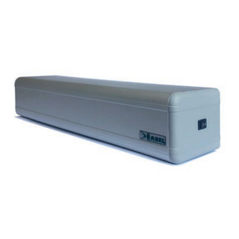
Label EVOLUS Manual

ASSEMBLY GUIDEBOOK
ASSEMBLY GUIDEBOOK
EVOLUS AUTOMATED
EQUIPMENT ASSEMBLY
GUIDEBOOK
EVOLUS
EVOLUS
“EVOLUS” ASSEMBLY GUIDEBOOK - GB - Rel.1.2- 03/2010 - CD0500ITA_GI
GB


NUT M6
(q.ty 18)
T.C.E.I.
M6x10
(q.ty 12)
T.C.E.I.
M6x8
(q.ty 6)
T.C.E.I.
M5x8
(q.ty 4)
T.C.E.I.
M5x10
(q.ty 4)
T.B.E.I.
M5x12
(q.ty 2)
T.C.E.I.
M5x20
(q.ty 4)
WASHER
M6
(q.ty 4)
KIT CONTENT
3
2
1
3
4
SIDE PANEL PAIR
ELECTRONIC CONTROL UNIT
MOTOR ASSEMBLY WITH ENCODER
COVER LINKS
CARRIAGE WITH DOUBLE WHEEL AND
THIRD ANTI-DERAILMENT WHEEL
510
6
7
8
9
UPPER BELT COUPLING
LOWER BELT COUPLING
CABLE GLAND
IDLE PULLEY
MECHANICAL LIMIT SWITCH
9
1
3
5
6
8
10
4
7
2
4
KIT OF SCREWS
1) WARNINGS
This assembly manual is addressed to professionally specialized personnel only.
Read carefully all the instructions before product assembly, as a wrong assembly could be a source of danger.
Before assembling the product, always check its integrity.
Keep packaging materials out of children's reach, as they might be a source of danger.

4
12
13
14
17
16
12 clip
transom
sliding rail
casing
casing compensating profile
rail gasket
brush
13
14
15
16
17
15
18
18
21
3
4
5
6
7
8
9
10
1
10
4
11
2
1
3
4
side panel pair
electronic control unit
motor assembly with encoder
cover links
carriage with double wheel and
third anti-derailment wheel
510
6
7
8
9
upper belt coupling
lower belt coupling
cable gland
idle pulley
mechanical limit switch
driving belt
11
FIG.1
FIG.2
2)COMPONENT ARRANGEMENT

5
2000
2500
3000
3500
4000
4500
5000
5500
6000
6500
949
1199
1449
1699
1949
2199
2449
2699
2949
3199
516,5
641,5
766,5
891,5
1016,5
1141,5
1266,5
1391,5
1516,5
1641,5
1575
1950
2325
2700
3075
3450
3825
4200
4575
4950
400 345
345
345
345
345
345
345
345
345
345
400
400
400
400
400
400
400
400
400
SINGLE DOOR RH LEAF
WITHOUT ELECTRIC LOCK
SINGLE DOOR LH LEAF
WITHOUT ELECTRIC LOCK
DOUBLE DOOR LEAF WITHOUT ELECTRIC LOCK
TRANSOM LENGTH LT
LT=2PL-B+2S+24
FREE PASSAGE PL
PL=(LT+B)/2-S-6
LEAF WIDTH LM
LM=(LT-B)/4+S/2-6
IDLE PULLEY F
LT*3/4+75 MOTOR M CONTROL UNIT C
2000
2500
3000
3500
4000
4500
5000
5500
6000
6500
968
1218
1468
1718
1968
2218
2468
2718
2968
3218
1008
1258
1508
1758
2008
2258
2508
2758
3008
3258
1913
2413
2913
3413
3913
4413
4913
5413
5913
6413
650 595
845
1095
1345
1595
1845
2095
2345
2595
2845
900
1150
1400
1650
1900
2150
2400
2650
2900
TRANSOM LENGTH LT
LT=2PL-B+S+24
FREE PASSAGE PL
PL=(LT+B-S)/2-12
LEAF WIDTH LM
LM=(LT-B+S)/2-12
IDLE PULLEY F
LT-87
MOTOR M
LT-LM-342
CONTROL UNIT C
LT-LM-397
S
LT
PL
B
LM
SS
B
LM LM
PL
LT
S
LT
PL
B
LM
F
M
C
F
M
C
M
C
F
2000
2500
3000
3500
4000
4500
5000
5500
6000
6500
968
1218
1468
1718
1968
2218
2468
2718
2968
3218
1008
1258
1508
1758
2008
2258
2508
2758
3008
3258
1913
2413
2913
3413
3913
4413
4913
5413
5913
6413
650 595
845
1095
1345
1595
1845
2095
2345
2595
2845
900
1150
1400
1650
1900
2150
2400
2650
2900
TRANSOM LENGTH LT
LT=2PL-B+S+24
FREE PASSAGE PL
PL=(LT+B-S)/2-12
LEAF WIDTH LM
LM=(LT-B+S)/2-12
IDLE PULLEY F
LT-87
MOTOR M
LT-LM-342
CONTROL UNIT C
LT-LM-397
FIG.3
FIG.4
FIG.5

2000
2500
3000
3500
4000
4500
5000
5500
6000
6500
943
1193
1443
1693
1943
2193
2443
2693
2943
3193
516,5
641,5
766,5
891,5
1016,5
1141,5
1266,5
1391,5
1516,5
1641,5
1575
1950
2325
2700
3075
3450
3825
4200
4575
4950
400 345
345
345
345
345
345
345
345
345
345
ELECTRIC LOCK E
1000
1250
1500
1750
2000
2250
2500
2750
3000
3250
400
400
400
400
400
400
400
400
400
SINGLE DOOR RH LEAF
WITH SLIM ELECTRIC LOCK
2000
2500
3000
3500
4000
4500
5000
5500
6000
6500
968
1218
1468
1718
1968
2218
2468
2718
2968
3218
SINGLE DOOR LH LEAF
WITH SLIM ELECTRIC LOCK
1008
1258
1508
1758
2008
2258
2508
2758
3008
3258
1913
2413
2913
3413
3913
4413
4913
5413
5913
6413
650 595
845
1095
1345
1595
1845
2095
2345
2595
2845
85
85
85
85
85
85
85
85
85
85
900
1150
1400
1650
1900
2150
2400
2650
2900
DOUBLE DOOR LEAF WITH SLIM ELECTRIC LOCK
FE
M
C
TRANSOM LENGTH LT
LT=2PL-B+2S+12
FREE PASSAGE PL
PL=(LT+B)/2-S-6
LEAF WIDTH LM
LM=(LT-B)/4+S/2-6
IDLE PULLEY F
T*3/4+100 MOTOR M CONTROL UNIT C ELECTRIC LOCK E
T/2 + 5
2000
2500
3000
3500
4000
4500
5000
5500
6000
6500
968
1218
1468
1718
1968
2218
2468
2718
2968
3218
1008
1258
1508
1758
2008
2258
2508
2758
3008
3258
2188
2688
3188
3688
4188
4688
5188
5688
6188
6688
525 470
720
970
1220
1470
1720
1970
2220
2470
2720
1903
2403
2903
3403
3903
4403
4903
5403
5903
6403
775
1025
1275
1525
1775
2025
2275
2525
2775
TRANSOM LENGTH LT
LT=2PL-B+S+24
FREE PASSAGE PL
PL=(LT+B-S)/2-12
LEAF WIDTH LM
LM=(LT-B+S)/2-12
IDLE PULLEY F
LT-212
MOTOR M
LT-LM-467
CONTROL UNIT C
LT-LM-522
ELECTRIC LOCK E
LT - 62
TRANSOM LENGTH LT
LT=2PL-B+S+24
FREE PASSAGE PL
PL=(LT+B-S)/2-12
LEAF WIDTH LM
LM=(LT-B+S)/2-12
IDLE PULLEY F
LT-87
E
F
M
C
MOTOR M
LT-LM-342
CONTROL UNIT C
LT-LM-397
ELECTRIC LOCK E
75
M
C
E
F
S
LT
PL
B
LM
SS
B
LM LM
PL
LT
S
LT
PL
B
LM
6
FIG.3-E
FIG.4-E
FIG.5-E

6) ASSEMBLY OF PARTS
Cut the rail gasket (17) 24mm shorter with respect
to the total length LT
Cut the sliding rail (14) 60mm shorter with
respect to the total length LT
Cut the covering guard (15) 24mm shorter with
respect to the total length LT
Cut the transom (13) 24mm shorter with respect to
the total length LT
Insert the rail gasket (17) in the lower slot of the transom making it adhere completely for the whole length and then
insert the sliding rail (14) on the rail gasket.
In order to facilitate the insertion, it is advisable to use a carriage with two lower wheels leaning on the
sliding rail and the central wheel adhering to the upper guide of the transom, and then to make it slide all
along the rail easing the rail positioning on the gasket.
12
7
34
56
12
1
14
3
1
6
5

Insert No. 10 nuts M6 in the upper slot of the transom which will be used to fix the motor, the control unit,the idle pulley
and the two cover links. In case three cover links are used (for transoms longer than 4500mm.), insert No. 12 nuts M6.
Insert No. 4 nuts M6 in the lower slot of the transom which will be used to fix the opening mechanical limit switch and
the closing mechanical limit switch or the electric lock, if any and if required.
78
Insert the carriage (5) in the transom and vertically adjust the central wheel by operating on the adjustment screw,
and by keeping the two side wheels leaning on the lower sliding guide.
The central wheel must only skim the upper part of the transom without pressing, so that the carriage can slide freely.
Now, take care that the carriage cannot get out of its seat
and that the central wheel performs its duty of anti-
derailment.
Insert two carriages for each leaf in the transom. In case of
double leaf, there are 4 carriages, the two internal
carriages have a belt coupling and the two external
carriages are free.
In case of single leaf, there are 2 carriages, the carriage on
the left has a belt coupling and the carriage on the right is
free, regardless of the opening direction.
Assemble the electric lock coupling bracket in the
first carriage on the left with respect to the electric lock,
if any, using No. 2 screws M5 X 8.
9
10
8
8
7
9
10

9
Assemble the electric lock coupling bracket in the
first carriage on the right with respect to the electric
lock, if any, using No. 2 screws M5 X 8.
Assemble the lower belt coupling in the left carriage, in case of single leaf, or in the internal carriage of the left leaf, in
case of double leaf, by using No. 2 screws M5 X 8.
Then assemble the belt block on the belt coupling by using No. 2 screws M5 X 10.
Assemble the upper belt coupling in the internal carriage of the right leaf, in case of double leaf, by using No. 2
screws M5 X 8.
Lower belt coupling Upper belt coupling
Fix the mechanical limit switch (10) to the left side of the transom, as per fig. 3, 4, 5 using screws M6 x 10 with
washers M6.
Apply the rubber buffer on the outer rh border of the limit switch.
This mechanical limit switch corresponds to the opening limit switch in case of double leaf door or single leaf door
with leftward opening, and to the closing limit switch in case of single leaf door with rightward opening without electric
lock.
11
12 13
14 15
11
12
13
14
15

Fix the second mechanical limit switch (10) in the centre of the transom in case of double leaf and only if the electric
lock is not present, as per fig. 3, using screws M6 x 10 with washers M6.
Apply the rubber buffer on the outer lh border of the limit switch.
This mechanical limit switch corresponds to the closing limit switch in case of double leaf door.
In case of single leaf door, fasten the mechanical limit switch to the right side of the transom, as per fig. 4 and 5.
This mechanical limit switch corresponds to the opening limit switch in case of single leaf door with rightward
opening, and to the closing limit switch in case of single leaf door with leftward opening without electric lock.
Fix the idle pulley (9) to the right side of the transom,
as per fig. 3, 4, 5 using screws M6x10.
16
17
Fix the motor assembly with encoder (3) to the right
side of the transom as per fig. 3, 4, 5 using screws
M6x10.
18
If required, fix the battery plate under the electronic control unit container, by fastening it with No. 2 t.c.c. screws 3.9 x
6.5 and place the emergency battery on it.
19 20
Fix the electronic control unit (2) to the right side of the transom, as per fig. 3, 4, 5 using screws M6x8.
Connect, to the electronic control unit, the motor cable, the encoder cable and the negative pole of the battery; the positive pole
will be connected after the automated equipment start-up.
The Battery charger board shall be inserted in the connector J1 of the electronic control unit.
21 22
10
16
17 18
19
20
21
22

11
Fix No. 2 support links of the cover (4) to the transom by using No. 2 screws M6x10 for each link and connect the
articulation by inserting the plastic pin.
In case of automated equipment longer than 4500mm. provide No. 3 support links, one of which must be exactly in
the centre of the transom.
The central link can be useful, in case of double leaf door, to support the motion radar connecting cable.
Should the third link be required to support the radar connecting cable, regardless of the transom length, it is
possible to order it separately.
Then, turn the articulation upwards towards the link, in
order to close it.
Install the driving belt (11) rolling it up around the idle
pulley; the belt tensioning screw of the pulley shall be
loosened.
Insert the driving belt in the bracket of the lower belt
coupling taking care to make it adhere thoroughly to
the eyelets provided in the bracket and lock it by
tightening the screw slightly.
Pull manually the belt from the upper side of the
pulley towards the inside of the transom and insert
it in the upper belt coupling bracket (only for double
leaf doors).
Take care to place the carriages with belt coupling
next to the closing mechanical limit switch or next to
the electric lock bracket, if any, before tightening
the belt block screws.
23 24
25 26
27
28
23
24
23
25 26
27 28

Roll the belt up around the motor pulley and pull it
· Finally, cut the driving belt, insert it in the lower belt coupling bracket, and lock it by tightening the screws.
Adjust the belt tensioning by screwing the side screw of the idle pulley and, once the required tension has been
reached, tighten the front screw.
Apply, in the upper part of transom No. 10,
the black plastic cable glands (8) inserting them as per
figure, and place them at regular spacings along the
whole length of the transom.
12
29
30 31
32 33
34
23
30
29
31
32
33
34

13
Install the plastic side panels (1), right and left, on the transom sides and fasten them by using two TCEI screws 5 x 20.
35
If the electric lock is required, place it in the centre of the transom in case of double leaf door, or on the right side of the
transom in case of single leaf door with leftward opening or to the left side of the transom in case of single leaf door
with rightward opening.
The electric lock lever shall hitch to the bracket provided on the carriage.
Comply with the fastening dimensions on fig.3-E, 4-E, 5-E and fasten the electric lock by using screws M6 x 10.
36
Roll the electric lock connecting cable up around the cable gland so that it cannot get entangled in the moving
devices, then connect it to the electric lock cabling by using two terminals and insert the connector of the electric lock
in the LOCK 1 connector of the electronic control unit.
40
35 36
37
39
40
37 38
39
38

14
Operation test
1. If the automated equipment is a single leaf door with rightward opening, set the dip 5 of S1 ON, if the automated
equipment is double leaf or single leaf door with leftward opening, set the dip 5 of S1 OFF.
2. If the automated equipment is an EVOLUS 90, set the dip 9 of S2 OFF; if it is an EVOLUS 150 set the dip 9 of S2
ON.
3. If the electric lock model FAIL-SAFE is present, set the dip 9 of S1 ON; if the electric lock model FAIL-SECURE is
present, set the 9 of S1 OFF.
4. Supply power to the control unit with 230Vac, that will emit an initial beep and a short series of close beeps.
5. Press and hold the PS2 SET-UP button as long as the control unit buzzer emits the fast beeps, then release it
when the control unit emits the 4 final beeps preceding motor starting.
6. The electric lock, if any, will free the hooking bracket on the carriage and the motor will run slowly in the closing
direction until when the carriages with belt coupling shall arrive at the end of stroke, afterwards, the motor will run
slowly in the opening direction.
After a small distance of opening stroke, turn off the control unit.
Close the container of the control unit with the cover by
screwing it with the two screws provided.
Insert the articulation of the link provided with pin under
the covering guard.
· Then, this articulation shall be coupled with the link which
had been fastened to the transom, in order to
guarantee the support of the guard when the automated
equipment is open.
41
42
43
41
42
43

15
Place the covering guard on the transom and
fasten it with a TBEI screw 5 X 20.
44 45
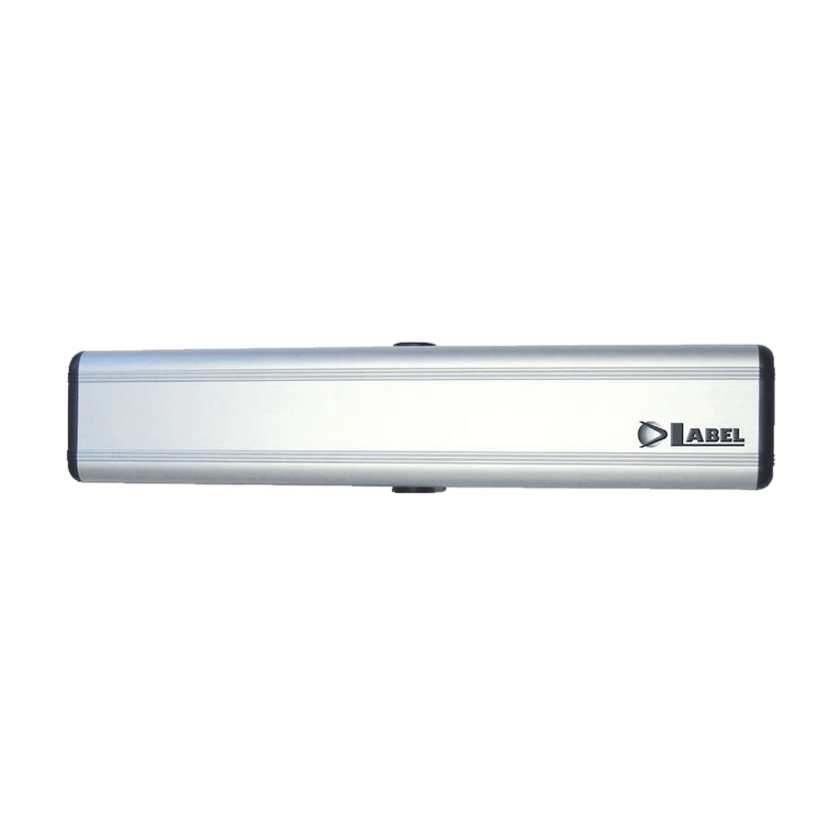
Finally, apply the label with the logo Label on the lower
right side of the guard.
44 45

ASSEMBLY GUIDEBOOK
ASSEMBLY GUIDEBOOK
LABEL S.p.A.
Via Ilariuzzi, 17/A - S.Pancrazio P.se - 43126 - Parma - Italy Tel.
(+39) 0521/6752 - Fax (+39) 0521/675222
www.labelspa.com
Other manuals for EVOLUS
1
Table of contents
Other Label Door Opening System manuals

Label
Label NEXT 120s User manual

Label
Label Neptis SMP User manual

Label
Label NEPTIS PLUS User manual

Label
Label ETERNA 70 User manual

Label
Label NEPTIS/LE User manual

Label
Label NEXT 75 User manual

Label
Label Neptis SLT-B User manual
Label
Label NEXT 75 User manual
Label
Label Neptis SMP User manual
Label
Label ETERNA 90 EASY User manual
Popular Door Opening System manuals by other brands

C.R. Laurence
C.R. Laurence CRL JACKSON 1295 installation instructions

Automatic Technology
Automatic Technology GDO-6 EasyRoller installation manual

Chamberlain
Chamberlain K1A6636 quick start guide

GEZE
GEZE GC 365 R manual

Dormakaba
Dormakaba G-SR EMR Series Fixing instructions

Schartec
Schartec Prime 600 Installation and operating instructions