Lacewing GH4064 User manual

1

2
MPORTANT SAFETY INFORMATION
The warnings, precautions, and instructions discussed in this manual cannot cover all possible conditions and
situations that may occur. The operator must understand that common sense and caution are factors, which
cann`t be built into this product, but must be supplied by the operator.
Assembly / Installation Precaution
1.Assemble only according to these instructions. Improper assembly can create hazards.
2.Wear ANSI-approved safety goggles and heavy-duty work gloves during assembly.
3.This unit contains pieces with sharp edges. The machined edges of the aluminium parts and the ends of
the panel clips may be sharp. Handle all parts carefully.
4.Keep assembly area clean and well lit.
5.Keep bystanders out of the area during assembly.
6.Do not assemble when tired or when under the influence of alcohol, drugs or medication.
7.Product capabilities apply to properly and completely assembled product only.
8.Locate the Greenhouse on a flat, level, surface. A concrete foundation is recommended for a high-quality
installation.
9.WARNING: The brass bushings inside the rollers of this product contain lead, a chemical known to cause
birth defects (or other reproductive harm).
Use / Service Precautions
1. This is not a toy. Do not allow children to play in or climb on this product. Although this greenhouse does
include some caps, there are still some exposed sharp edges. In addition, protective covers may fall off in
time. Children must be supervised if allowed near the greenhouse.
2. Show / Debris Accumulation Hazard. The heavy weight of accumulated snow or other debris can cause
parts of this greenhouse to buckle suddenly. Do not allow debris to accumulate on top of the greenhouse. If
snowfall is expected, place additional supports (not provided) underneath the Crow. Never enter a
greenhouse with accumulated debris on top.
3. Use as intended only.
4. Inspect periodically, replace damaged parts immediately and do not enter greenhouse if parts are loose or
damaged,
5. For your safety,service and maintenance should be performed regularly by a qualified technician.
3

4
5
Read the ENTIRE IMPORTANT SAFETY INFORMATION
section at the beginning of this document including all text under subheadings therein before set up or use of this
product.
IMPROTANT - READ THE FOLLOWING CAREFULLY BEFORE PROCEEDING
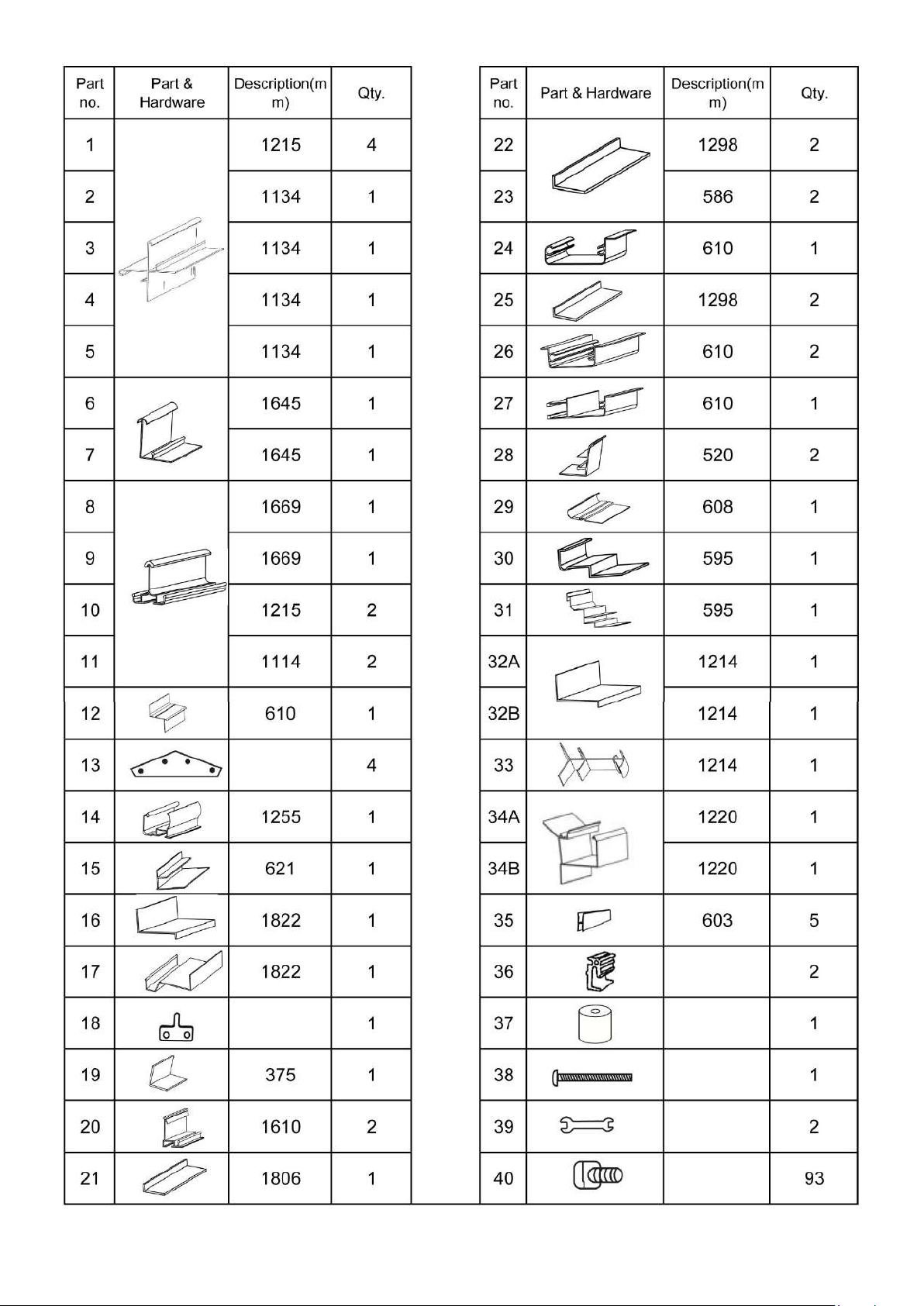
Unless noted otherwise, attach all frame parts using the Bolts 40 and Nuts 48 provided. Tighten nuts by
hands. After installing all the PC panels, continue tightening nuts by tools about 1/4 turn .be careful not to
over tighten
Lay out all parts by number prior to assembly.
Use an assistant or an appropriate support (not included) to keep the partially assembled parts upright during
assembly. Use two assistants to assemble the Crown pieces to the rest of the frame.
Assemble on a clear, calm day. Wind will damage the Greenhouse and make assembly difficult.
Assembling the Foundation
Prior to assembly, a proper foundation must be laid. The greenhouse must be properly supported to help prevent
property damage and injury in the event of strong winds or inclement weather. Wind and ground conditions may
vary from site to site, and may affect the practicality and effectiveness of anchoring methods substantially. If you
have any doubt regarding the stability of the foundation you are to use, consult a professional.
It is always your responsibility to ensure that the greenhouse is properly anchored. Our company cannot be held
responsible for personal injury, damage to the greenhouse, or other property damage that occurs as result of
improperly anchoring the greenhouse.
Be certain to check with local authorities to obtain all required building permits and familiarize yourself with any
building codes that may apply.
Decide on a location for the greenhouse. The location should optimally be a level, well-lit area that is sheltered
from the wind. The door of the greenhouse should not open towards the prevailing wind, if possible.
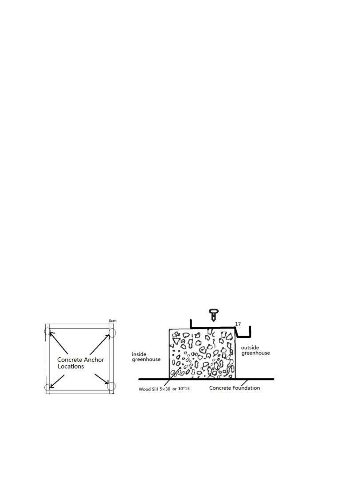
Concrete Anchor Foundation
This foundation will be assembled out of 6x6cm treated wood, hardware and prefabricated concrete anchors
(none provided).
Assemble the 6x6cm treated wood into a frame according to the dimensions shown in the diagram below.
The wood needs to be trimmed to fit. Make certain that the assembly is square and level.
Securely assemble the frame together using proper hardware.
Dig a hole for each of the concrete anchors in the positions shown. The hole should be slightly oversized and
should be deep enough so that the frame will rest almost on the ground when installed.
Place the anchors in the holes carefully, then place the 6x6cm treated wood frame on the anchors. Use a level on
the frame to make sure that the anchors are sunk to the proper depth. If any anchors need to be raised, partially
fill the hole with sand or gravel under the anchor.
6
Once the frame is level, secure it to the anchors. Fill up the holes with the earth you removed previously.
Treated wood base foundation
The wood base will be assembled out of 10x15 and 5x30 treated wood, hardware (galvanized lag bolts / deck
screws), and filling material (such as gravel, none provided)
Assemble the 5x30 treated wood into a frame according to the dimensions shown in the diagram below.
The wood needs to be trimmed to fit. Make certain that the assembly is square and level. Also use a level to
ensure that the base is even.
Assemble the 10x15 treated wood on top of the 5x30 treated wood base you just assembled, as shown in the
cross section below. Fill with filling material (such as gravel) up to the top of 4x6 wood’s inside of the base.
Note: No matter which foundation you choose, position the four greenhouse’s bottom frames with their outer
edges overhanging the outer edges of the base, as shown in the diagrams. Secure four bottom frames to the
base after finishing assembling the greenhouse.
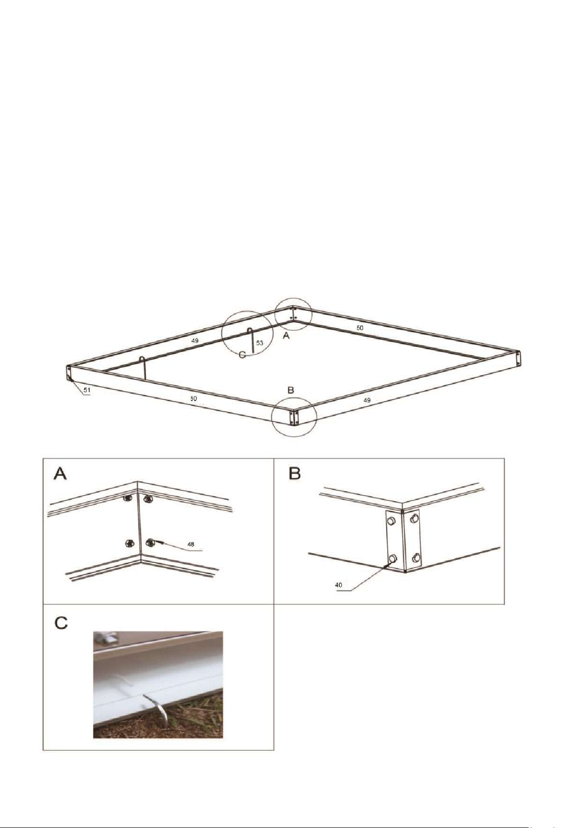
Assembling the Base
Put the foundation parts in orders according to the below diagram. Then use the fasteners, bolts and nuts to
connect all the foundation parts.
Fix the base plate into the ground with screw, and hook the base plate frame with clasps
7
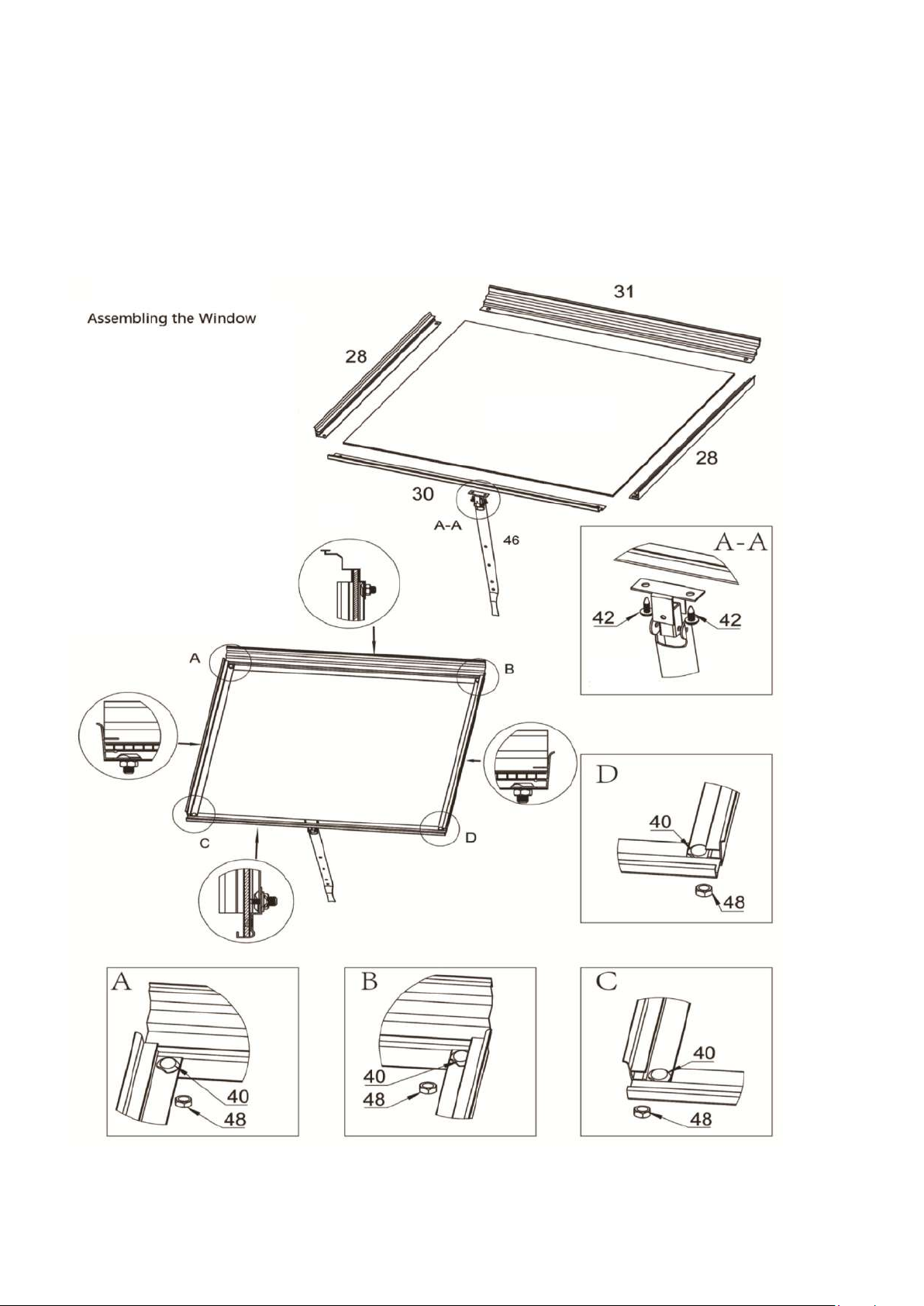
Assembling the window
Follow the steps below for the window.
1. Attach the side window frame 28 to the top window frame 31, as shown in below picture.
2. Insert the bolts 40 into the holes at the bottom of the side window frames 28, so that the threads stick out the
bottom of the window.
3. Remove the protective film from the window pane 5. Slide the window pane 5 into the three sided frame.
4. Slide the bottom window frame 30 onto the bolts 40 which are on the frames 28. Secure it in place with nuts 48.
5. Attach the window brace 46 to the bottom window frame 30 with two window screws 42, the holes on the
window brace 46 should face away from the window.
Assembling the Door
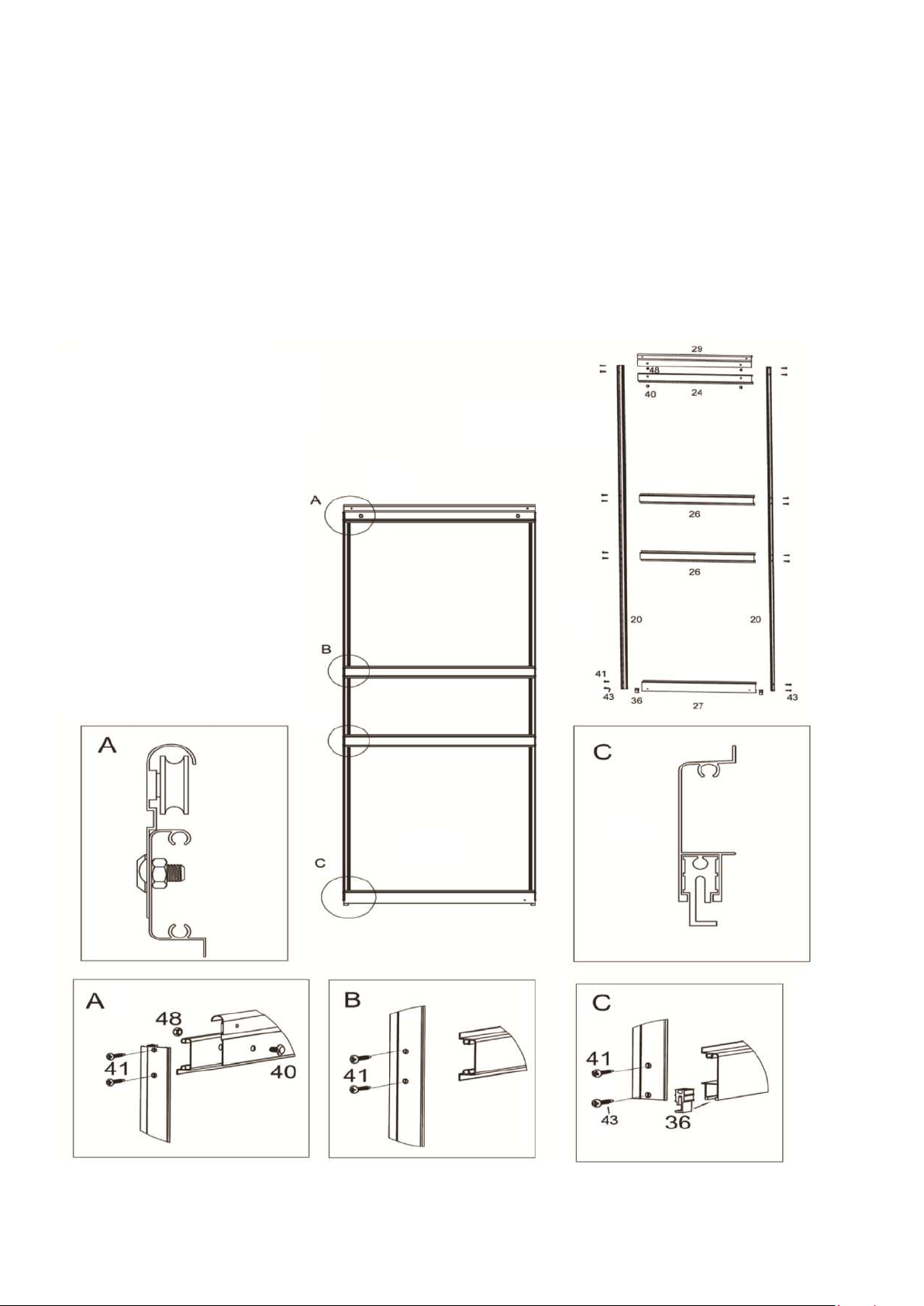
8
The door is assembled using the door screws 41.
The screws thread directly into the rounded portions of the parts in the center of the door.
1. Attach the center door frames 26 to the side door frames 20.
2. Attach the top door frame 24 to the side door frames 20 with the rounded portion facing the front as shown in
the picture.
3. Attach the door slider frame 29 to the top door frame 24 using two bolts 40 and two nuts 48 with the roller on
the top of the door.
4. Insert a door bottom slider 36 into each end of the bottom door frame 27. Install the slider correctly, with the
gap facing the back of the door, see the picture below. Attach the bottom door frame 27 to the side door frames 20
with screws 41 and 43, using two screws on each side - the top screw 41 into the bottom door frame 27 and the
bottom screw 43 into the door bottom slider 36.
9
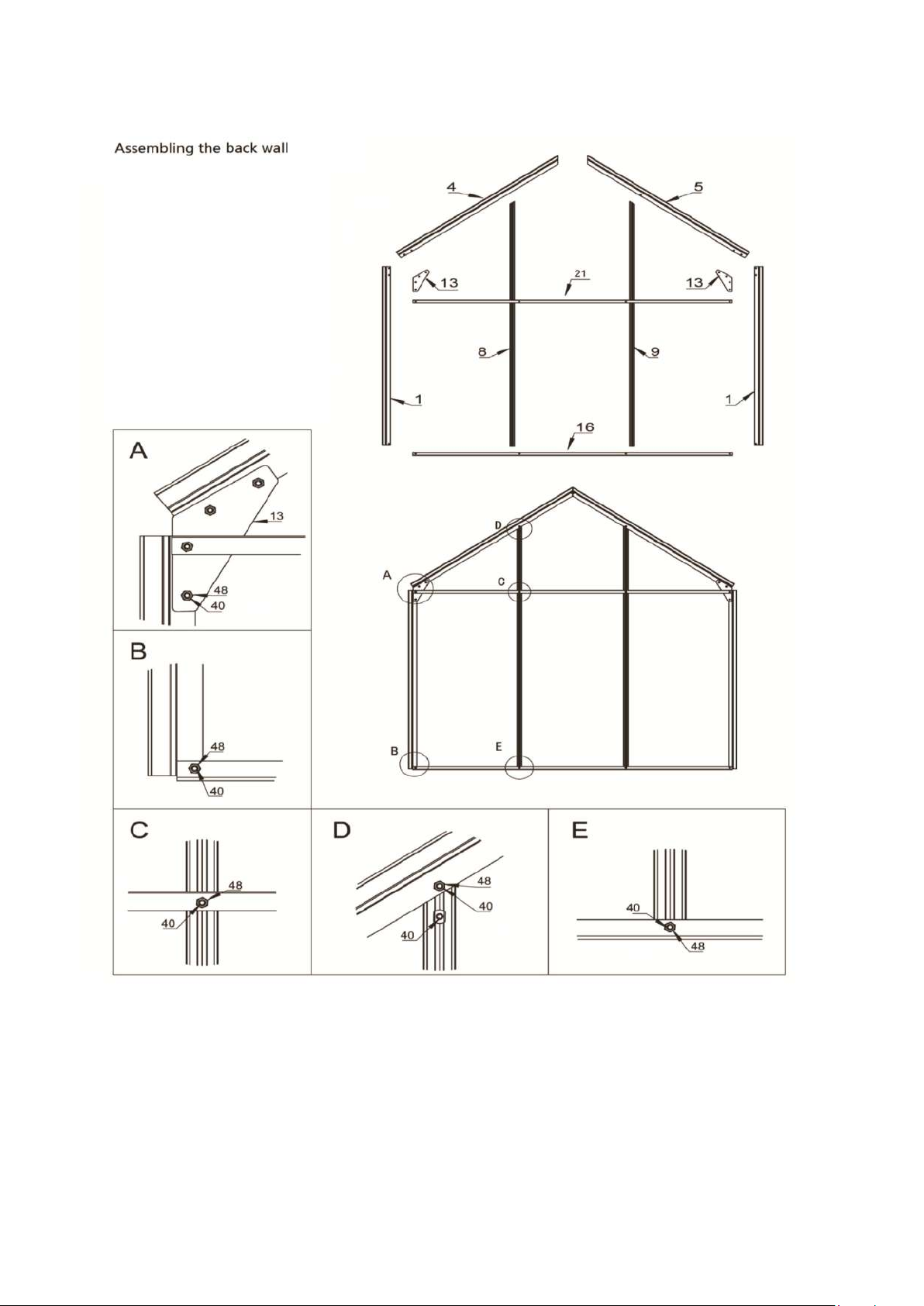
Assembling the back wall
Place 1,4,5,8,9,13,16 and 21 as shown in the picture, insert the screws 40 from bottom to top and tighten by nuts
48.
Assembling the front wall
1. Place 1,2,3,6,7,12,13,17,23 and 25 as shown in the picture, insert the screws 40 from bottom to top and tighten
by nuts 48.
2. Attach the frame12 to the middle of 2 and 3, the cutoff corners of 2 and 3should be at the top and should face
away from the center.
3. Attach the frame 19 to 3 with the door bolt 38 and nut 48, with the door support spacer 37 between the frame
19 and 3.
4. Place three bolts 40 in the slot at the back of the door rail 14. Attach the rail 14 to the top doorway frame 12 and

10
the free end of the vertical frame 19, with the rounded side up.
Assembling the side wall.
Place 10,22,32 and 34 as shown in the picture, insert the screws 40 from bottom to top and tighten by nuts 48.
Other Lacewing Greenhouse Kit manuals


Popular Greenhouse Kit manuals by other brands

ACD PRESTIGE
ACD PRESTIGE MR3 H manual

Vitavia
Vitavia VA0040-TRP Assembly instructions

VegTrug
VegTrug Nursery manual

Riverstone Networks
Riverstone Networks Monticello 041315V Assembly instructions

STC
STC Easy Grow 6x12 Greenhouse Assembly instructions

CLIMA POD
CLIMA POD Spirit V7 Series Assembly instructions


