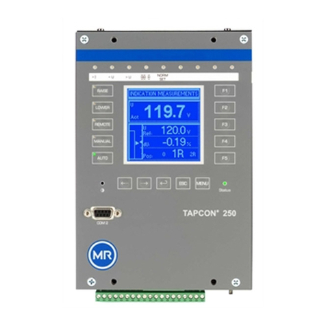
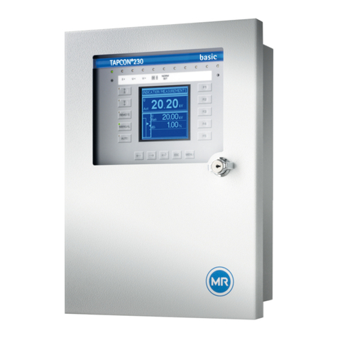
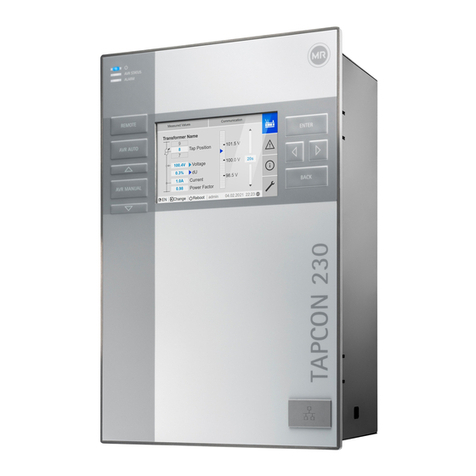
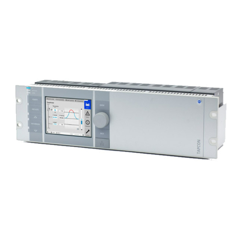
MR TAPCON 230 Expert User manual

Voltage regulator
TAPCON®230 Expert
Operating instructions
7817454/02 EN

© All rights reserved by Maschinenfabrik Reinhausen
Dissemination and reproduction of this document and use and disclosure of its content are strictly prohibited
unless expressly permitted.
Infringements will result in liability for compensation. All rights reserved in the event of the granting of patents,
utility models or designs.
The product may have been altered since this document was published.
We reserve the right to change the technical data, design and scope of supply.
Generally the information provided and agreements made when processing the individual quotations and orders
are binding.
The original operating instructions were written in German.

Table of contents
Maschinenfabrik Reinhausen GmbH 2021 37817454/02 EN TAPCON®230 Expert
Table of contents
1 Introduction......................................................................................................................... 7
1.1 Manufacturer....................................................................................................................................... 7
1.2 Completeness..................................................................................................................................... 7
1.3 Safekeeping........................................................................................................................................ 7
1.4 Notation conventions .......................................................................................................................... 7
1.4.1 Hazard communication system .............................................................................................................................7
1.4.2 Information system................................................................................................................................................9
1.4.3 Instruction system .................................................................................................................................................9
1.4.4 Typographic conventions ....................................................................................................................................10
2 Safety................................................................................................................................. 11
2.1 Appropriate use ................................................................................................................................ 11
2.2 Inappropriate use.............................................................................................................................. 12
2.3 Fundamental safety instructions....................................................................................................... 12
2.4 Personnel qualification...................................................................................................................... 14
2.5 Personal protective equipment ......................................................................................................... 15
3 IT security.......................................................................................................................... 16
3.1 General............................................................................................................................................. 16
3.2 Operation.......................................................................................................................................... 16
3.3 Commissioning ................................................................................................................................. 16
3.4 Communication interfaces ................................................................................................................ 17
3.5 Encryption standards........................................................................................................................ 17
4 Product description.......................................................................................................... 19
4.1 Scope of delivery .............................................................................................................................. 19
4.2 Function description of the voltage regulation .................................................................................. 19
4.3 Performance features ....................................................................................................................... 20
4.4 Operating modes .............................................................................................................................. 21
4.5 Design............................................................................................................................................... 22
4.5.1 Display, operating elements and front interface..................................................................................................22
4.5.2 LEDs ...................................................................................................................................................................23
4.5.3 Connections and fuses........................................................................................................................................24
4.5.4 Nameplate...........................................................................................................................................................25
4.5.5 Safety markings ..................................................................................................................................................26

Table of contents
Maschinenfabrik Reinhausen GmbH 202147817454/02 ENTAPCON®230 Expert
4.5.6 Connection diagram and grounding screw..........................................................................................................26
4.5.7 Visualization ........................................................................................................................................................27
5 Packaging, transport and storage .................................................................................. 33
5.1 Suitability, structure and production ................................................................................................. 33
5.2 Markings ........................................................................................................................................... 33
5.3 Transportation, receipt and handling of shipments........................................................................... 33
5.4 Storage of shipments........................................................................................................................ 34
6 Mounting ........................................................................................................................... 35
6.1 Preparation ....................................................................................................................................... 35
6.2 Minimum distances........................................................................................................................... 36
6.3 Assembly variants............................................................................................................................. 36
6.3.1 Flush panel mounting..........................................................................................................................................36
6.3.2 Wall mounting with housing (optional) ................................................................................................................38
6.4 Connecting device ............................................................................................................................ 40
6.4.1 Cable recommendation .......................................................................................................................................40
6.4.2 Electromagnetic compatibility..............................................................................................................................41
6.4.3 Connecting cables to the system periphery ........................................................................................................44
6.4.4 Connecting the CAN bus.....................................................................................................................................44
6.4.5 Connecting SCADA.............................................................................................................................................47
6.4.6 Wiring voltage measurement/current measurement UI.......................................................................................51
6.4.7 Wiring analog inputs AI .......................................................................................................................................52
6.4.8 Wiring digital inputs DI ........................................................................................................................................53
6.4.9 Wiring digital outputs DO ....................................................................................................................................54
6.4.10 Wiring resistor contact series ..............................................................................................................................54
6.4.11 Connecting the power supply..............................................................................................................................54
6.5 Performing tests................................................................................................................................ 56
7 Initial steps........................................................................................................................ 57
7.1 Establishing connection to visualization ........................................................................................... 57
8 Commissioning................................................................................................................. 60
8.1 Commissioning wizard...................................................................................................................... 60
8.2 Function tests ................................................................................................................................... 60
8.2.1 Checking measured values and status of digital inputs and outputs ..................................................................61
8.2.2 Testing the device control function......................................................................................................................61
8.2.3 Checking parallel operation.................................................................................................................................62

Table of contents
Maschinenfabrik Reinhausen GmbH 2021 57817454/02 EN TAPCON®230 Expert
9 Operation........................................................................................................................... 67
9.1 System.............................................................................................................................................. 67
9.1.1 General ...............................................................................................................................................................67
9.1.2 Configuring the network ......................................................................................................................................69
9.1.3 Setting the device time........................................................................................................................................70
9.1.4 Setting the screensaver ......................................................................................................................................71
9.1.5 Configuring syslog...............................................................................................................................................72
9.1.6 SCADA................................................................................................................................................................74
9.1.7 Linking signals and events ..................................................................................................................................80
9.1.8 Configuring analog inputs ...................................................................................................................................83
9.1.9 Configuring digital inputs and outputs .................................................................................................................85
9.1.10 Event management .............................................................................................................................................87
9.1.11 User administration .............................................................................................................................................88
9.1.12 Hardware.............................................................................................................................................................92
9.1.13 Software ..............................................................................................................................................................92
9.1.14 Import/export manager........................................................................................................................................92
9.2 Power grid......................................................................................................................................... 95
9.2.1 Transformer data.................................................................................................................................................95
9.2.2 Voltage monitoring ............................................................................................................................................100
9.2.3 Current monitoring ............................................................................................................................................102
9.2.4 Power monitoring ..............................................................................................................................................104
9.2.5 Power flow monitoring.......................................................................................................................................106
9.2.6 TAPCON® 2xx retrofit.......................................................................................................................................107
9.3 On-load tap-changer regulator........................................................................................................ 109
9.3.1 Voltage regulation .............................................................................................................................................109
9.3.2 Line drop compensation....................................................................................................................................118
9.3.3 Parallel operation ..............................................................................................................................................121
9.3.4 U bandwidth monitoring ....................................................................................................................................130
9.4 On-load tap-changer....................................................................................................................... 132
9.4.1 Tap position monitoring.....................................................................................................................................132
9.4.2 Tap position capture method.............................................................................................................................133
9.4.3 Target-tap-position operation ............................................................................................................................135
9.4.4 Information about the on-load tap-changer .......................................................................................................135
9.5 Motor-drive unit and control cabinet ............................................................................................... 136
9.5.1 Control of the motor-drive unit...........................................................................................................................136
10 Maintenance and care .................................................................................................... 140
Table of contents
Maschinenfabrik Reinhausen GmbH 202167817454/02 ENTAPCON®230 Expert
11 Fault elimination ............................................................................................................. 141
11.1 General faults ................................................................................................................................. 141
11.2 No regulation in AUTO mode.......................................................................................................... 141
11.3 Unwanted on-load tap-change operation........................................................................................ 142
11.4 Human-machine interface............................................................................................................... 142
11.5 Incorrect measured values ............................................................................................................. 142
11.6 Parallel operation faults .................................................................................................................. 143
11.7 Tap position capture incorrect ........................................................................................................ 144
11.8 Other faults ..................................................................................................................................... 145
12 Disposal........................................................................................................................... 146
13 Technical data................................................................................................................. 147
13.1 Display elements ............................................................................................................................ 147
13.2 Materials ......................................................................................................................................... 147
13.3 Dimensions..................................................................................................................................... 147
13.4 Power supply .................................................................................................................................. 147
13.5 Voltage measurement and current measurement .......................................................................... 148
13.6 Central processing unit................................................................................................................... 149
13.7 Digital inputs ................................................................................................................................... 151
13.8 Digital outputs................................................................................................................................. 152
13.9 Analog inputs.................................................................................................................................. 154
13.10 Communication interfaces .............................................................................................................. 156
13.11 Tap position capture / resistor contact series ................................................................................. 158
13.12 Ambient conditions ......................................................................................................................... 158
13.13 Standards and directives ................................................................................................................ 158
13.14 Connection diagrams...................................................................................................................... 160
TAPCON® 230 Expert ......................................................................................................................................161
Glossary .......................................................................................................................... 164

1 Introduction
Maschinenfabrik Reinhausen GmbH 2021 77817454/02 EN TAPCON®230 Expert
1 Introduction
This technical file contains detailed descriptions on the safe and proper in-
stallation, connection, commissioning and monitoring of the product.
It also includes safety instructions and general information about the prod-
uct.
This technical file is intended solely for specially trained and authorized per-
sonnel.
1.1 Manufacturer
The product is manufactured by:
Maschinenfabrik Reinhausen GmbH
Falkensteinstraße 8
93059 Regensburg
Tel.: (+49) 9 41/40 90-0
E-mail: [email protected]
Further information on the product and copies of this technical file are avail-
able from this address if required.
1.2 Completeness
This technical document is incomplete without the following supporting docu-
ments:
▪ Connection diagrams
▪ Operating Instructions
– Available as a download on the device
– Available for download at www.reinhausen.com
– Available for download in the MR Customer Portal
1.3 Safekeeping
Keep this technical document and all supporting documents ready at hand
and accessible for future use at all times. Download the operating instruc-
tions from the device. The operating instructions are also available on the
Maschinenfabrik Reinhausen GmbH website and in the MR Customer Portal.
1.4 Notation conventions
1.4.1 Hazard communication system
Warnings in this technical file are displayed as follows.

1 Introduction
Maschinenfabrik Reinhausen GmbH 202187817454/02 ENTAPCON®230 Expert
1.4.1.1 Warning relating to section
Warnings relating to sections refer to entire chapters or sections, sub-sec-
tions or several paragraphs within this technical file. Warnings relating to
sections use the following format:
WARNING Type of danger!
Source of the danger and outcome.
► Action
► Action
1.4.1.2 Embedded warning information
Embedded warnings refer to a particular part within a section. These warn-
ings apply to smaller units of information than the warnings relating to sec-
tions. Embedded warnings use the following format:
DANGER! Instruction for avoiding a dangerous situation.
1.4.1.3 Signal words and pictograms
The following signal words are used:
Signal word Definition
DANGER Indicates a hazardous situation which, if not avoided, will result in
death or serious injury.
WARNING Indicates a hazardous situation which, if not avoided, could result
in death or serious injury.
CAUTION Indicates a hazardous situation which, if not avoided, could result
in minor or moderate injury.
NOTICE Indicates measures to be taken to prevent damage to property.
Table1: Signal words in warning notices

1 Introduction
Maschinenfabrik Reinhausen GmbH 2021 97817454/02 EN TAPCON®230 Expert
Pictograms warn of dangers:
Pictogram Definition
Warning of a danger point
Warning of dangerous electrical voltage
Warning of combustible substances
Warning of danger of tipping
Warning of danger of crushing
Table2: Pictograms used in warning notices
1.4.2 Information system
Information is designed to simplify and improve understanding of particular
procedures. In this technical file it is laid out as follows:
Important information.
1.4.3 Instruction system
This technical file contains single-step and multi-step instructions.
Single-step instructions
Instructions which consist of only a single process step are structured as fol-
lows:

1 Introduction
Maschinenfabrik Reinhausen GmbH 202110 7817454/02 ENTAPCON®230 Expert
Aim of action
üRequirements (optional).
► Step 1 of 1.
ðResult of step (optional).
ðResult of action (optional).
Multi-step instructions
Instructions which consist of several process steps are structured as follows:
Aim of action
üRequirements (optional).
1. Step 1.
ðResult of step (optional).
2. Step 2.
ðResult of step (optional).
ðResult of action (optional).
1.4.4 Typographic conventions
Typographic convention Purpose Example
UPPERCASE Operating controls, switches ON/OFF
[Brackets] PC keyboard [Ctrl] + [Alt]
Bold Software operating controls Press Continue button
…>…>… Menu paths Parameter > Control parameter
Italics System messages, error messages,
signals
Function monitoring alarm triggered
[► Number of pages] Cross reference [► Page 41].
Dotted underscore
.............................................
Glossary entry, abbreviations, defini-
tions, etc.
Glossary entry
........................
Table3: Typographic conventions used in this technical file

2 Safety
Maschinenfabrik Reinhausen GmbH 2021 117817454/02 EN TAPCON®230 Expert
2 Safety
▪ Read this technical file through to familiarize yourself with the product.
▪ This technical file is a part of the product.
▪ Read and observe the safety instructions provided in this chapter.
▪ Read and observe the warnings in this technical file in order to avoid func-
tion-related dangers.
▪ The product is manufactured on the basis of state-of-the-art technology.
Nevertheless, risks to life and limb for the user or impairment of the prod-
uct and other material assets due to the function may arise in the event of
improper use.
2.1 Appropriate use
The device keeps the output voltage of a transformer with an on-load tap-
changer constant. The product is designed solely for use in stationary large-
scale electrical energy systems and facilities.
If used as intended, in compliance with the requirements and conditions
specified in this technical document and observing the warning notices in
this technical document and attached to the product, the product does not
pose a risk of injury or damage to property or the environment. This applies
throughout the service life of the product, from delivery, installation and oper-
ation to removal and disposal.
The following is considered intended use:
▪ You will find the standard valid for the product and the year of issue on the
nameplate.
▪ Operate the product in accordance with this technical document, the
agreed-upon delivery conditions and the technical data.
▪ Ensure that all necessary work is performed by qualified personnel only.
▪ Only use the equipment and special tools included in the scope of delivery
for the intended purpose and in accordance with the specifications of this
technical document.
▪ Only operate the product in industrial areas.
▪ Observe the notices in this technical document regarding electromagnetic
compatibility and the technical data.
▪ The product is intended for installation. Make sure that all fire safety pre-
cautions and protection against electric shock are met.
▪ Make sure that the resistance to mechanical stress is met.

2 Safety
Maschinenfabrik Reinhausen GmbH 202112 7817454/02 ENTAPCON®230 Expert
2.2 Inappropriate use
Use is considered to be inappropriate if the product is used other than as de-
scribed in the Intended use section. In addition, observe the following:
▪ The product is not a protective device. Do not use it to handle safety-re-
lated functions.
▪ Do not operate the product in potentially explosive areas.
2.3 Fundamental safety instructions
To prevent accidents, malfunctions and damage as well as unacceptable ad-
verse effects on the environment, those responsible for transport, installa-
tion, operation, maintenance and disposal of the product or parts of the prod-
uct must ensure the following:
Personal protective equipment
Loosely worn or unsuitable clothing increases the danger of becoming
trapped or caught up in rotating parts and the danger of getting caught on
protruding parts. This poses a danger to life and limb.
▪ Wear appropriate personal protective equipment such as a helmet, work
gloves, etc. for the respective activity.
▪ Never wear damaged personal protective equipment.
▪ Never wear rings, necklaces, or other jewelry.
▪ If you have long hair, wear a hairnet.
Work area
Untidy and poorly lit work areas can lead to accidents.
▪ Keep the work area clean and tidy.
▪ Make sure that the work area is well lit.
▪ Observe the applicable laws for accident prevention in the relevant coun-
try.
Working during operation
The product may only be operated in a sound, operational condition. Other-
wise it poses a danger to life and limb.
▪ Regularly check the operational reliability of safety equipment.
▪ Comply with the inspection work, maintenance work and maintenance in-
tervals described in this technical file.

2 Safety
Maschinenfabrik Reinhausen GmbH 2021 137817454/02 EN TAPCON®230 Expert
Invisible laser radiation
Looking directly into the beam or the reflected beam can cause eye damage.
The beam is emitted at the optical connections or at the end of the fiber-optic
cables connected to them on the assemblies. Read the chapter "Technical
Data" [►Section 13, Page 147] for further information.
▪ Never look directly into the beam or the reflected beam.
▪ Never look into the beam with the aid of optical instruments such as a
magnifying glass or a microscope.
▪ In the event that the laser beam strikes your eyes, close your eyes imme-
diately and move your head out of the path of the beam.
Working with current transformers
Dangerous high voltages may occur when a current transformer is operated
with an open secondary circuit. This can lead to injuries and property dam-
age.
▪ Never operate a current transformer with an open secondary circuit; short-
circuit the current transformer to prevent this.
▪ Observe the information in the current transformer operating instructions.
Handling electrical components
Electrical components can be damaged by electrostatic discharge.
▪ Never touch electrical components during commissioning, operation or
maintenance work.
▪ Take suitable measures (such as covers) to ensure that personnel cannot
touch components.
▪ Wear suitable personal protective equipment.
Explosion protection
Highly flammable or explosive gases, vapors and dusts can cause serious
explosions and fire.
▪ Do not install or operate the product in areas where a risk of explosion is
present.
Safety markings
Warning signs and safety information plates are safety markings on the
product. They are an important aspect of the safety concept.
▪ Observe all safety markings on the product.
▪ Make sure all safety markings on the product remain intact and legible.
▪ Replace safety markings that are damaged or missing.

2 Safety
Maschinenfabrik Reinhausen GmbH 202114 7817454/02 ENTAPCON®230 Expert
Ambient conditions
To ensure reliable and safe operation, the product must only be operated
under the ambient conditions specified in the technical data.
▪ Observe the specified operating conditions and requirements for the in-
stallation location.
Modifications and conversions
Unauthorized or inappropriate changes to the product may lead to personal
injury, material damage and operational faults.
▪ Only modify the product after consultation with Maschinenfabrik Rein-
hausen GmbH.
Spare parts
Spare parts not approved by Maschinenfabrik Reinhausen GmbH may lead
to physical injury, damage to the product and malfunctions.
▪ Only use spare parts that have been approved by Maschinenfabrik Rein-
hausen GmbH.
▪ Contact Maschinenfabrik Reinhausen GmbH.
2.4 Personnel qualification
The person responsible for assembly, commissioning, operation, mainte-
nance and inspection must ensure that the personnel are sufficiently quali-
fied.
Electrically skilled person
The electrically skilled person has a technical qualification and therefore has
the required knowledge and experience, and is also conversant with the ap-
plicable standards and regulations. The electrically skilled person is also pro-
ficient in the following:
▪ Can identify potential dangers independently and is able to avoid them.
▪ Is able to perform work on electrical systems.
▪ Is specially trained for the working environment in which (s)he works.
▪ Must satisfy the requirements of the applicable statutory regulations for
accident prevention.
Electrically trained persons
An electrically trained person receives instruction and guidance from an
electrically skilled person in relation to the tasks undertaken and the poten-
tial dangers in the event of inappropriate handling as well as the protective
devices and safety measures. The electrically trained person works exclu-
sively under the guidance and supervision of an electrically skilled person.

2 Safety
Maschinenfabrik Reinhausen GmbH 2021 157817454/02 EN TAPCON®230 Expert
Operator
The operator uses and operates the product in line with this technical file.
The operating company provides the operator with instruction and training
on the specific tasks and the associated potential dangers arising from im-
proper handling.
Technical Service
We strongly recommend having maintenance, repairs and retrofitting carried
out by our Technical Service department. This ensures that all work is per-
formed correctly. If maintenance is not carried out by our Technical Service
department, please ensure that the personnel who carry out the mainte-
nance are trained and authorized by Maschinenfabrik Reinhausen GmbH to
carry out the work.
Authorized personnel
Authorized personnel are trained by Maschinenfabrik Reinhausen GmbH to
carry out special maintenance.
2.5 Personal protective equipment
Personal protective equipment must be worn during work to minimize risks to
health.
▪ Always wear the personal protective equipment required for the job at
hand.
▪ Never wear damaged personal protective equipment.
▪ Observe information about personal protective equipment provided in the
work area.
Protective clothing Close-fitting work clothing with a low tearing strength,
with tight sleeves and with no protruding parts. It mainly
serves to protect the wearer against being caught by
moving machine parts.
Safety shoes To protect against falling heavy objects and slipping on
slippery surfaces.
Safety glasses To protect the eyes from flying parts and splashing liq-
uids.
Visor To protect the face from flying parts and splashing liq-
uids or other dangerous substances.
Hard hat To protect against falling and flying parts and materials.
Hearing protection To protect against hearing damage.
Protective gloves To protect against mechanical, thermal, and electrical
hazards.
Table4: Personal protective equipment

3 IT security
Maschinenfabrik Reinhausen GmbH 202116 7817454/02 ENTAPCON®230 Expert
3 IT security
Observe the following recommendations to operate the product safely.
3.1 General
▪ Ensure that only authorized personnel have access to the device.
▪ Only use the device within an ESP (electronic security perimeter). Do not
connect the device to the Internet in an unprotected state. Use mecha-
nisms for vertical and horizontal network segmenting and security gate-
ways (firewalls) at the transition points.
▪ Ensure that the device is only operated by trained personnel who are fa-
miliar with IT security.
3.2 Operation
Observe the following recommendations during device operation:
▪ Change the password at regular intervals.
▪ Export the security log at regular intervals.
▪ Check the log files regularly for unauthorized system access and other se-
curity-related events.
3.3 Commissioning
Observe the following recommendations for device commissioning:
▪ User IDs must be unique and assignable. Do not use a "Group account"
function or the "Auto login" function.
▪ Activate the "Auto logout" function.
▪ Restrict the rights of the individual user groups as much as is feasible; this
helps avoid errors during operations. A user with the "Operator" role, for
example, should only perform operations and should not be able to
change any device settings.
▪ Delete or disable the default "admin" user ID. This requires first creating a
new user account with the "Administrator" role. You can then use it to
delete or disable the default "admin" account.
▪ Deactivate service user access.
▪ Enable SSL/TLS encryption [►Section 9.1.1, Page 67]; access to the
device is then only possible using the SSL/TLS protocol. In addition to en-
crypting communication, this protocol also checks the authenticity of the
server.
▪ Use TLS version1.2 or higher wherever possible.
▪ Integrate the device into a public key infrastructure. Create your own SSL
certificates for this if necessary and then import them.
▪ Connect the device to a central log server by using the syslog interface.

3 IT security
Maschinenfabrik Reinhausen GmbH 2021 177817454/02 EN TAPCON®230 Expert
3.4 Communication interfaces
1
2
3
4
5
6
X1
RY
SICAM A8000 CP - 8050
ER
X2
X3
X4
X5
ETH
ETH
RS-485
RS-232
Figure1: Interfaces: CPU
Interface Protocol Port Description
X2 TCP 102 IEC61850
X2 TCP 502 Modbus1)
X2 TCP 20000 DNP31)
X2 TCP 2404 IEC 60870-5-104 1)
X3 TCP 80 HTTP for web-based visualization2)
X3 TCP 443 HTTPS for web-based visualization
X3 TCP 22 SSH server3)
X4 - - Serial interface (SCADA)
X5 - - Serial interface (SCADA)
Table5: Interfaces and open ports of the CPU assembly
1) Default setting; if you have modified the port for the control system proto-
col, only the set port is open.
2) Port is closed if you activate the device's SSL encryption.
3) SSH is disabled when MR service access is disabled.
3.5 Encryption standards
The device supports the following TLS versions:
▪ TLS 1.0
▪ TLS 1.1
▪ TLS 1.2

3 IT security
Maschinenfabrik Reinhausen GmbH 202118 7817454/02 ENTAPCON®230 Expert
The device uses the following cipher suites for a TLS-secured connection:
Key exchange Authentication Encryption Key length Operating
mode
Hash func-
tion
TLS ECDHE RSA WITH AES 128 CBC SHA
DHE SHA265
ECDHE ECDSA GCM SHA256
ECDH 256 CBC SHA
RSA SHA256
GCM SHA384
Table6: Cipher suite
The device uses the SHA512 hash function to save passwords.

4 Product description
Maschinenfabrik Reinhausen GmbH 2021 197817454/02 EN TAPCON®230 Expert
4 Product description
4.1 Scope of delivery
Check the shipment for completeness based on the shipping documents.
▪ Voltage regulator
▪ RJ45 patch cables
▪ Shield clamps
▪ Plug connectors
▪ Tension clamps
▪ Technical documents
▪ Additional nameplate
▪ Terminating resistor for CAN bus
▪ Terminating resistor for RS485 bus
Optional
▪ Housing for wall mounting
▪ Device type-dependent:
– Ethernet to FO converter (SFP module)
– Serial to FO converter
4.2 Function description of the voltage regulation
The device keeps the output voltage of a transformer with an on-load tap-
changer constant.
The device compares the transformer's measured voltage (Uactual) with a de-
fined reference voltage (Udesired). The difference between Uactual and Udesired is
the control deviation dU.
The device parameters can be adjusted to the line voltage behavior to
achieve a balanced control response with the on-load tap-changer only per-
forming a small number of tap-change operations.

4 Product description
Maschinenfabrik Reinhausen GmbH 202120 7817454/02 ENTAPCON®230 Expert
Summer Winter
Load profile of the grid
Control variable
Line voltage
Control path
Regulating transformer
Automatic voltage regulator
Desired value
Line voltage
Measurement
transformer
Automatic voltage regulator
Such as for parallel operation
of up to 16transformers
SCADA
Long-distance communication and control center
Inputs
Digital and analog
Figure2: Overview of voltage regulation
4.3 Performance features
▪ Web-based visualization
▪ Automatic voltage regulation
– 1 to 3 desired values
▪ Desired value setting
– Analog
– Using TDSC
▪ Line drop compensation
– R&X compensation: Compensation for voltage drops on the line
– Z compensation: Compensation for voltage fluctuations in the meshed
grid
▪ Integrated monitoring functions:
– Voltage monitoring
– Current monitoring
– Apparent power monitoring
– Active power monitoring
This manual suits for next models
2
Table of contents
Other MR Controllers manuals
Popular Controllers manuals by other brands

National Instruments
National Instruments CompactRIO NI cRIO-9012 operating instructions

Sanyo
Sanyo SHA TM64 AGB instruction manual

Reclaim
Reclaim v1 manual

TIM
TIM Mirus MC ISO Additional information

KLING & FREITAG
KLING & FREITAG CD 44 user manual

controlair
controlair 400 Installation, operation and maintenance instructions