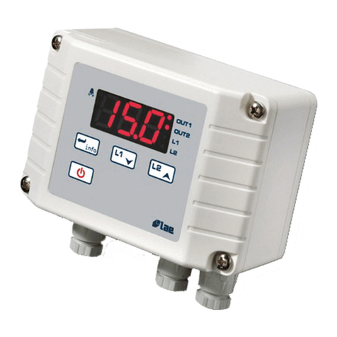
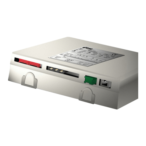
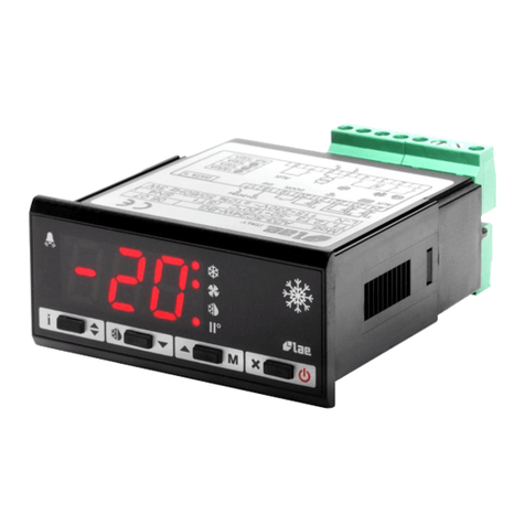
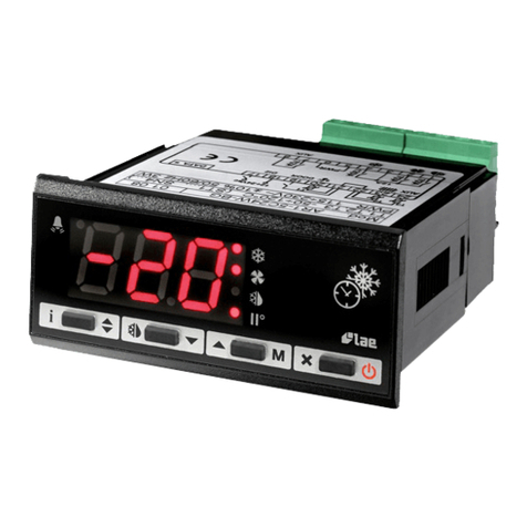
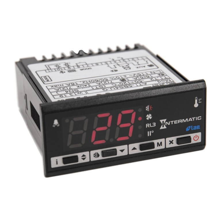
SDU is a controller allowing temperature and
defrost control of static and ventilated
refrigerators.
To get best performance, before installing
and using it, read this instruction sheet
carefully.
1 INSTALLATION
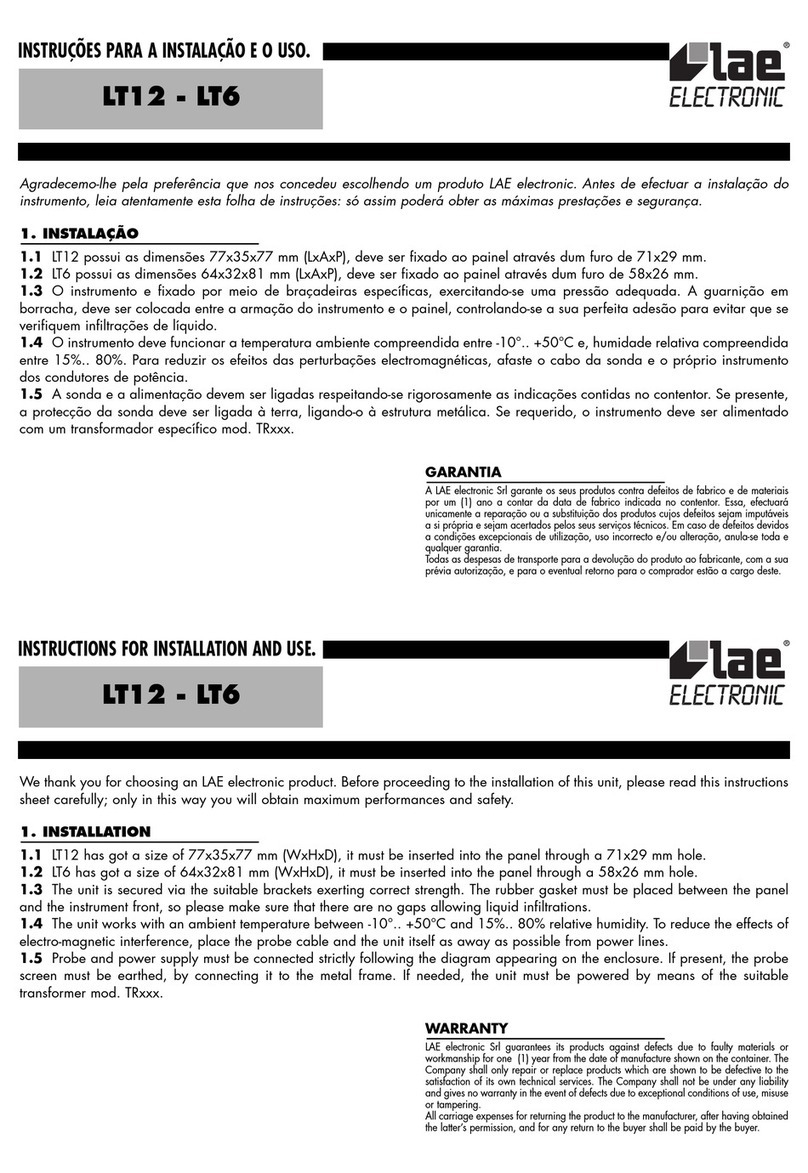
1a The instrument is secured to the panel
from the rear, after making a 29x71 mm
hole, by means of the suitable brackets,
exerting correct strength. If using the rubber
gasket (“S” version), this must be interposed
between the panel and the instrument bezel,
checking the perfect adhesion carefully.
1b For proper functioning the instrument
needs an ambient temperature between
-10°...+50°C and 15%...80% relative
Humidity. To improve protection of the probe
against electro-magnetic interference, which
might compromise its function, place its cable
and the controller away from power lines.
1c Probe, power supply and outputs must be
connected strictly following the diagram on
the enclosure, where the maximum switching
powers and supply voltage are indicated,
too.
The probe screen must not be connected to
any other leads. If the external transformer is
needed, the instrument must be powered by
the suitable transformer supplied by LAE
(mod. TR...).
1d Should the instrument be recalibrated,
in consequence of probe replacement or
considerable cable lengthening, then proceed
as follows: use an accurate thermometer,
make sure that the two probes are at the
same temperature, immersing them in a liquid
if necessary. By means of a screwdriver turn
the trimmer located close to the inscription
“0°ADJ.”.
CAUTION!:
• If the relays switch large loads frequently, we
suggest you contact us to obtain information about the
relay contact life.
• Where delicate or valuable products have to be
maintained in special conditions, we recommend not to
use the same instrument for both control and limit
functions.
2 FUNCTIONING DESCRIPTION
After having installed the instrument and
carried out the connections, power the
instrument.
2a The setpoint, which represents the
On/Off switching temperature of the cooler,
is displayed by pushing ; to change its
value within the limits programmed in SETUP,
while is kept pressed, push to increase
or to decrease. When is released, the
new programmed value is stored.
2b In order to start manual defrost, keep
keys and pressed for 3 sec.; to stop it,
follow the same procedure.
2c When the alarm is entered, as a result of
the temperature staying above the higher
alarm threshold or below the lower one for
longer than the delay (see SETUP), the
indication "AL" is alternated with the actual
temperature; if the unit is fitted with a buzzer
and/or alarm relay, this latter is switched on.
The alarm condition is stored, therefore the
alarm signallings continue regardless of the
temperature. By pressing any of the keys the
buzzer is muted the relay is switched off and,
if the temperature has returned within the
setpoint limits, the indication "AL" disappears;
as long as the alarm condition exists, every
30 min. the buzzer/relay is switched On for
1 min.
During defrost the high alarm is inhibited.
2d The On status of the output and defrost
phase are shown on display through the
lighting up of the LED’s placed close to the
relative symbols.
2e As a result of probe failure, its
connection breakdown or overrange, "PF" is
displayed and the buzzer/relay is switched
on immediately, which can be muted by
pressing any of the pushbuttons. The
compresseur output will operate according to
the duty cycle programmed in SETUP.
2f It’s possible to simulate the behaviour of a
thermal mass inside the refrigerator; this
allows to avoid rapid fluctuations of the
displayed temperature, resulting for example
from door opening or defrost, but also to
reduce hunting due to temperature control.
The fluctuation speed of the displayed
temperature depends on the value assigned to
“Si”; it’s however possible to display the
instantaneous temperature as long as the key
is kept pressed.
3 SETUP
SDU configuration is made through
programming of the control parameters;
access to it is possible through a sequence of
operations preventing accidental activation.
3a Keep keys + + pressed for 3 sec.,
exactly in this sequence.
To select the desired parameter press key .
To show its value press and if necessary
change it via or ; store it with . No
key activation within 10 sec. causes the
controller to switch over to the basic
functioning. It’s also possible to select a
specific parameter and change its value by
following the diagram attached.
3b Parameter description:
SL: minimum setpoint limit (-19°...+99°C).
Sh: maximum setpoint limit (SL...+99°C).
hY: hysteresis which, added to the Set
Point, determines the on switching threshold
of the cooler relay (+01°...+10°K). When you
have to maintain a very small hysteresis hY,
we recommend to program a suitable value
for Pc to ensure a long life to relay/contactor
and compressor.
Pc: it represents the minimum Off time of
the output. It’s the minimum time between Off
and On switching of the cooler regardless of
the temperature measured by the probe
(00...10 minutes).
Po: it allows to programme an offset between
the measured and the displayed temperature
(-19°...+19°K).
PF: in case of probe failure, defrosts are
suspended and the cooler run is not
controlled by setpoint but it is determined by
PF which represents the duty cycle
(00...10*10%), that is the On time and the
Off time within a 10 min. cycle. For ex.: 06=
6 min. On, 4 min. Off. This value should be
calculated keeping into consideration the
normal cooler duty cycle. This function allows
to avoid damage to the goods when the
actual temperature can not be measured as a
result of a probe failure. The minimum
intervention time, during which the operator
can not interrupt the cycle, has 10 min.
duration.
dt: the interval between a defrost and the
next (01...24 hours); defrost duration is not
included. In case of a power failure, when
the power comes on again, the defrost timer
re-starts the counting from the point where it
was interrupted, with ±30 min.
approximation.
dd: defrost duration, i.e. the cooler off cycle
(01...99 minutes).
do: if set at 01, it allows defrost
optimisation, by considering as defrosts
cooler pauses of duration equal or greater
than dd. For ex. dd= 20 min. If the cooler
remains off for 20 min. without interruption,
the timer will be reset and as a consequence
the start of the next defrost will be postponed.
If do= 00, optimisation is excluded.
dF: it allows to select the display indication
during defrost. If dF=00, then the
temperature measured by the probe continues
to be displayed; if -1, the display shows "dF"
until the setpoint is reached again. If
dF=01...99 min., "dF" is displayed all
through defrost and after until the time
programmed has elapsed, unless the setpoint
is achieved before.
AL: lower alarm threshold (-19°C...SL).
Ah: higher alarm threshold (Sh...+99°C).
Ad: it allows to: exclude the alarm function
(-1); programme a delay between the
detection of the alarm condition and its
signalling (00...99 minutes).
Si: by programming a value between 01 and
99 you establish the thermal mass to be
simulated, if 00 is selected the instantaneous
probe temperature is displayed; the greater
the programmed value, the greater the
resulting display slow down will be. It is
important to note that temperature and alarm
control are based on the instantaneous air
temperature and are therefore not
influenced by “Si” values.
YY: 01 DO NOT CHANGE. In case the
value 00 is selected by mistake, after exit
from the SETUP it’s not possible to have
access to it again by following the sequence
described at point 3a.
Act as follows: switch off the unit; while the
three pushbuttons are kept pressed, turn on
the unit again.
WARRANTY
LAE electronic Srl warrant that their products are free of
any defects in workmanship and materials for a period of 1
(one) year from date of production shown on the enclosure.
LAE electronic Srl shall only repair or replace those
products of which defects are due to LAE electronic Srl and
recognised by their technicians. LAE electronic Srl are not
liable for damages resulting from malfunctions of the
products.
Defects due to exceptional operating conditions,
misapplication and/or tampering will void the warranty.
All transport charges for returning the product to the
manufacturer, after prior authorisation by LAE electronic
Srl, and for the return to the purchaser are always for the
account of the purchaser.
SDU
