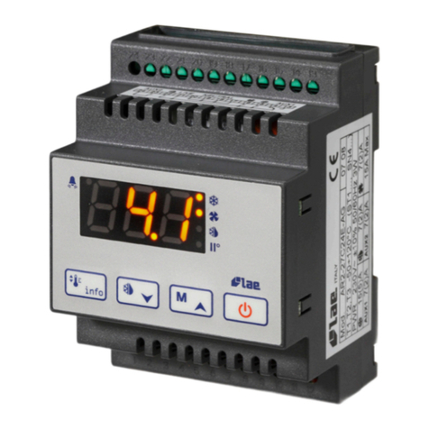
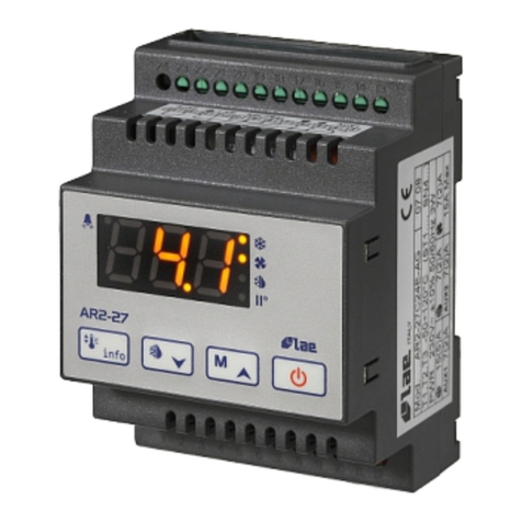
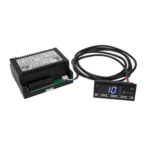
LAE RDC122T1R2 User manual

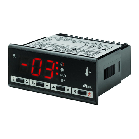
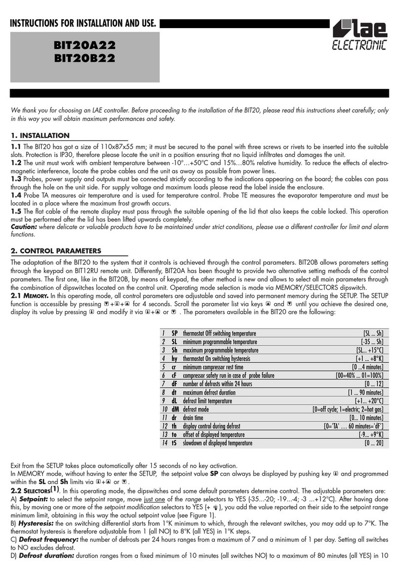
We thank you for choosing an LAE controller. Before proceeding to the installation of the RDC 12, please read this instructions sheet carefully;
only in this way you will obtain maximum performances and safety
1. INSTALLATION
1.1 The instrument has got a size of 77x35x97 mm (WxHxD). It’s inserted into the panel through a 71x29 mm hole and secured via the
suitable brackets exerting corret strength. The rubber gasket must be placed between the panel and the instrument front, so please make sure
that there are no gaps allowing liquid infiltrations.
1.2 The unit works with an ambient temperature between -10°...+50°C and 15%...80% relative Humidity. To reduce the effects of electro-
magnetic interference, place the cables carrying signals (probes and serial connections) and the controller as away as possible from power
lines.
1.3 Probes, power supply and outputs must be wired strictly following the diagram indicated on the enclosure, where the maximum loads
also appear. For supply voltage, the suitable transformer (mod. TRxxx) must be used.
1.4 Probe T1 measures air temperature and is used for the thermostat function; probe T2 measures the evaporator temperature and must be
secured to it on the place where the maximum frost growth occurs.
1.5 The RS485 serial communication port is available on the DATA connector. PIN 1 is identified by a dot.
Caution: • If the relays switch a large load frequently, we suggest you contact us to obtain information about the relay contact life.
• Where delicate or valuable products have to be maintained under strict conditions, please use a different controller for limit and alarm
functions.
2. CONTROL PARAMETERS
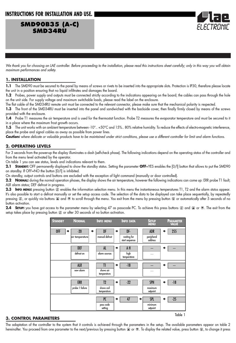
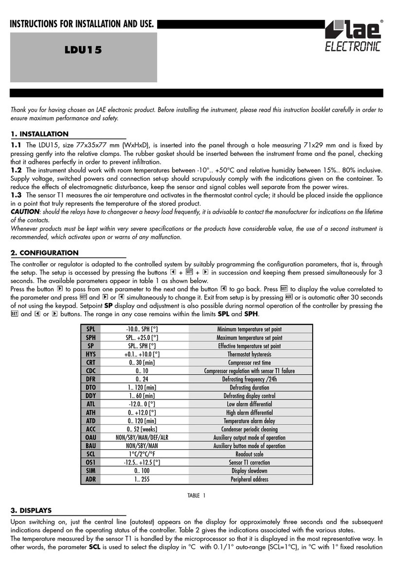
The adaptation of the RDC 12 to the the system that it controls is achieved through the parameters in the SETUP. Access to the parameters is
obtained by pressing + + for 4 seconds. Scroll through the parameters by pressing or until you select the desired one. Check its
value by means of and change it via + or . Exit from the SETUP occurs after 10 seconds of no key activation. To help yourself during
programming, refer to the following table.
3. DISPLAYS
3.1
DURING ORDINARY CONTROL.
At the power up, the display shows “—-” for 5 sec. during which the unit carries out a self-check; then
the temperature T3 appears. In some cases, owing to the structure of the cabinet or air stratification, the probes can not measure the desired
SPL minimum programmable temperature [-50 ... +150°]
SPh maximum programmable temperature [SPL ... +150°]
hyS thermostat on switching hysteresis [+01 ... +20°K]
coF cooler minimum off time [00 ... 10 minutes]
con cooler minimum on time [00 ... 10 minutes]
cdc cooler safety run in case of probe failure [00=off ... 10(0)%=always on]
crS cooler re-start delay after power failure [00 ... 120 seconds]
dLi defrost limit temperature [+01 ... +70°]
dto defrost time out [01 ... 120 minutes]
drP drain time [00 ... 10 minutes]
diS display control during defrost [-01=”dEF”; 00=”T3”; 1... 30 minutes=timed “dEF”]
dty defrost type [Fan=off cycle; ELE=electrical; GAS=hot gas]
Fct evaporator fan control [-01=always on; 00=on/off with cooler; 1... 10 minutes=delayed off]
FrS fan re-start after defrost [-50 ... +150°]
Fid ventilation during defrost [00=off; 01=T2<FrS; 02=always on]
Alo low alarm threshold [-50 ... +150°]
Ahi high alarm threshold [ALo ... +150°]
AdL temperature alarm delay [-01=excluded; 00... 120 minutes]
Ain alarm input selection [probe 1, 2, 3]
oS1 thermostat probe offset [-20 ... +20°K]
oS2 evaporator probe offset [-20 ... +20°K]
oS3 displayed probe offset [-20 ... +20°K]
SiM slowdown of displayed temperature [00 ... 200]
Adr peripheral number [00 ... 255]
INSTRUCTIONS FOR INSTALLATION AND USE.
RDC122T1R2
RDC122T1R3B
RDC122T1R3J

temperature. If necessary, through the parameters oS1, oS2 and oS3 the temperatures t1,and t2 measured by the probes can be adjusted
in order to obtain the desired values for computing: thermostat T1=t1+oS1; defrost T2=t2+oS2; display T3=t1+oS3.
Ex.: Setpoint= -20°; oS1= -2°K; oS3= +6°K, temperature t1 is controlled at -18° and the display shows -12°.
Through the SiM parameter it’s possible to reduce the fluctuations of the displayed temperature by simulating the behaviour of product core
temperature. The slowdown is proportionated to the value programmed to SiM (ex.: 100 simulates approx. a 0.5 l bottle of water). To display
the instantaneous temperatures T1, T2 or T3 press , or respectively.
3.2
DURING DEFROST.
The display is controlled according to the parameter diS, if 00 temperature T3 continues to be displayed. If diS=
-01, then the display shows “dEF” since defrost start as long as the temperature T1 is higher than setpoint+hysteresis hyS. By programming
a value between 1and 30 min., after the defrost “dEF” is still displayed until the time programmed has elapsed unless the above condition
is reached before.
3.3
OTHER DISPLAY STATUS.
During an alarm condition, “ALM” blinks on display. The stand-by status, in which all outputs are off, is signalled
with permanent “—-”. If the keypad has been locked through the serial communication, when attempting to perform any changes, the display
shows “inh”.
4. THERMOSTAT FUNCTION
At power-up the cooler start is delayed by the sum of coF and crS; this latter is used in those applications where it is necessary, after a line
dropout, to avoid simultaneous starts of many compressors at the power-up. For ex.: coF= 03, crS= 05; after power-up, at least 03 minutes
and 05 seconds must elapse before the cooler starts. coF and con are, respectively, the cooler minimum off and on time. The relay which
controls the cooler, after switching off/on or on/off, will remain in that status for at least the pre-programmed time. When you have to maintain
a very small hysteresis hyS, we recommend to program a suitable value for coF and con to ensure a long life to relay/contactor and
compressor.
Temperature control is based on the comparison between temperature T1, the setpoint and the hysteresis hyS programmed. The setpoint is
displayed by pressing . To change it, keep pressed and by pushing key or , select the desired value within the limits SPL and SPh.
The cooler on switching temperature is achieved by adding hyS to the setpoint.
Ex.: setpoint=-03; hyS=04, the relay is off with T1=-03°C and on with T1=+01°C.
When a failure or overrange of probe T1 occurs, the cooler run isn’t controlled according to setpoint but determined by cdc which represents
the cooler duty cycle, i.e. (on time)/(10 minute cycle). For ex.: 04= 4 minutes on time, 6 minutes off time. The cdc value has to be set taking
into consideration the normal cooler duty cycle.
If you wish to switch off the outputs, you can put the RDC12 on a standby via the serial communication or manually, by pressing ++
during self-check following the power-up. During the standby temperature measurement and serial communication however remain active. If
the RDC12 is on a standby, you can get it to go out of this status and resume its ordinary operation by following the same procedure as
described above .
5. DEFROST SETTINGS
Defrost is started when the real time, kept by the internal clock, matches one of the 6 scheduled times.
You have got access to clock and defrost times by keeping + pressed for 4 seconds. To move from one value to the next/previous, press
/ . To display it press , change it by pressing + or .
5.1
CLOCK PROGRAMMING.
To set the minutes of the real time, select Min and press + or . As to the hours, select hrS and proceed
as above. The clock programming range is from 00:00 to 23:59. Be careful if clock programming takes place at the end of an hour (10:59:59
- 11:00:00), if necessary check the clock again before you go further.
The real time is kept even in case of a power failure for a minimum of 5 days, typically 20 days.
5.2
DEFROST PROGRAMMING.
The six defrost start times are identified by the mnemonic dh1... dh6. The time is adjustable in hours and
tens of minutes i.e. 072 and 130 correspond to 7:20 and 13:00. The times assigned to dh1... dh6 do not need to be sequential.
If you want to eliminate one or more defrosts, simply program 240.
Two or more defrosts with time difference smaller or equal to 10 minutes are considered as one defrost. Ex.: dh1=073, dh2=073, dh3=074
there will be one defrost only at 7:30.
The defrost start times are stored in a non-volatile memory and therefore they are not lost in case of a black-out.
5.3 MANUAL DEFROST.
It is possible to manually start or abort defrost by pushing + .
6. DEFROST FUNCTION
6.1 EVAPORATOR HEATING.
During defrost the status of the outputs is determined by parameter dty. If dty=Fan, then the evaporator fans
are kept on, while cooler and defrost outputs are off. If dty=ELE, during defrost the cooler is switched off and the defrost output on. If
dty=GAS, cooler and defrost outputs are on all through defrost.
6.2 TERMINATION.
When defrost is on, it can be terminated on either temperature, when T2 matches the dLi value, or when the maximum
time dto has elapsed.
6.3 DRIPPING.
After the heating phase, the dripping time drP, by delaying the cooler re-start, allows a homogeneous heat spread all over
the evaporator and the drain of the drops of water.
INSTRUCTIONS FOR INSTALLATION AND USE.

The defrost LED is lit when the corresponding output is On; it blinks during defrost through “air blowing” and dripping time.
When probe T2 is faulty, any new defrost is inhibited.
7. EVAPORATOR FAN CONTROL
7.1 RUN WITH THERMOSTAT.
During temperature control, the fans can work in three different ways. If Fct=-01, the fans work continuously.
If Fct=00, the fans are stopped simultaneously with the cooler. If Fct is set between 1and 10 minutes, after the cooler has stopped, the fans
continue to run for the programmed amount of minutes. In both latter two cases, the fans are switched on simultaneously with the cooler.
7.2 RUN DURING AND AFTER DEFROST.
During and immediately after defrost, the fans are controlled by parameters Fid and FrS. If Fid=00,
at the start and all through defrost the fans are off; they are switched on again, after compressor re-start, when the evaporator probe T2
matches the FrS temperature. If Fid=01; in this case the fans are active as long as the evaporator has a temperature lower than FrS. If
Fid=02; all through defrost the fans are on (even with dty=ELE or GAS).
8. ALARM FUNCTION AND PROBE FAILURE
A check on the correct refrigeration plant function is performed by monitoring temperature T1, T2 or T3, selectable via Ain parameter. ALo
and Ahi determine, respectively, the lower and higher temperature alarm threshold.
AdL allows the control of the alarm function: with -01 the temperature alarm is excluded, while, if this parameter is 00, the alarm output is
on immediately when the condition is detected. If AdL is programmed between 01 and 120 minutes, the temperature must constantly remain
over the alarm threshold for the chosen time before the signallings take place.
When the alarm starts, “ALM” blinks on the display, alarm relay and buzzer are switched on. The signallings remain, even when the
alarm condition is over, until the alarm is “acknowledged” by pressing any key. Now, if the temperature is within the alarm limits, any
alarm indication disappears. Otherwise the current temperature is displayed alternating with “ALM”, the relay is always on and, for 1 min.
every 30, the buzzer beeps; all this happens as long as the alarm condition persists.
As a result of failure or overrange of one of the probes, the display shows either “PF1” or “PF2”, the alarm output is switched on immediately.
Also in this case the condition must be acknowledged by pressing any key.
The alarm output contact is also closed when the instrument is powerless.
During defrost and dripping, the high alarm monitoring is inhibited.
9. PROBE RE-CALIBRATION
Should it be necessary to recalibrate the unit, for instance in consequence of probe replacement, then act in the following way: get an accurate
reference thermometer or calibrator; make sure that the offset oSx of the probe to be re-calibrated is 00; switch off then on the unit.
During the self check (5 seconds from power-up), press + + . When the re-calibration function is active choose the desired section by
means of or : 0A1 and 0A2 allow 0°C calibration of the respective probe. SA1 and SA2 allow high temperature calibration to rectify
a gain error. After selecting the desired parameter, press + or to match the read-out value with the one of the reference instrument
(make sure the temperature is stable).
Exit from the recalibration occurs after 10 seconds of no key activation. Therefore, to avoid exit, keep pressed for as long as you need.
10. SERIAL COMMUNICATION
If fitted, the RS485 serial port allows the RDC12 to take part as a peripheral in a data communication network managed by a master PC
supervisor. The data base puts all measurement and control data on line as well as the output status. Adr is the unit identification number
within the network.
Through the serial communication it’s possible to change all control parameters (setpoint and SETUP), start defrost cycles, put the controller on
a standby or inhibit the controller keypad in order to avoid unauthorised access to programming function.
WARRANTY
LAE electronic Srl warrant that their products are free of any defects in workmanship and materials for a period of 1 (one) year from date of production
shown on the enclosure. LAE electronic Srl shall only repair or replace those products of which defects are due to LAE electronic Srl and recognised by their
technicians. LAE electronic Srl are not liable for damages resulting from malfunctions of the products.
Defects due to exceptional operating conditions, misapplication and/or tampering will void the warranty.
All transport charges for returning the product to the manufacturer, after prior authorisation by LAE electronic Srl, and for the return to the purchaser are
always for the account of the purchaser.

WIRING DIAGRAM
VIA PADOVA, 25
31046 ODERZO /TV /ITALY
TEL. 0422 815320 - 815303
TELEFAX 0422 814073
www.lae-electronic.com
E-mail: [email protected]
PARTNER VENEZIA • 041 5460713
INSTRUCTIONS FOR INSTALLATION AND USE.
SETUP
1SPL -50 ... 150 -30
2SPh SPL ... 150 20
3hyS 01 ... 20 02
4coF 00 ... 10 00
5con 00 ... 10 00
6cdc 00 ... 10 05
7crS 00 ... 120 00
8dLi 01 ... 70 10
9dto 01 ... 120 30
10 drP 00 ... 10 03
11 diS -01 ... 30 10
12 dty FAn; ELE; GAS ELE
13 Fct -01; 00... 10 01
14 FrS -50 ... 150 -10
15 Fid 00; 01; 02 00
16 Alo -50 ... 150 -32
17 Ahi Alo ... 150 22
18 AdL -01; 00... 120 10
19 Ain 1; 2; 3 01
20 Ado —————- 01 Don’t change
21 oS1 -20 ... 20 00
22 oS2 -20 ... 20 00
23 oS3 -20 ... 20 00
24 SiM 00 ... 200 00
25 Adr 00 ... 255 01
This manual suits for next models
2
Table of contents
Other LAE Controllers manuals
Popular Controllers manuals by other brands

Ltech
Ltech WiFi-RDM01 user manual

Unitronics
Unitronics Vision OPLC V130-J-TR20 installation guide

Kampmann
Kampmann 30515 Assembly and installation instructions

Sven
Sven AVR SLIM-1000 LCD Operation manual

Federal Signal Corporation
Federal Signal Corporation SignalMaster 330104 SMC1 instructions

Traxxas
Traxxas XL-5 instructions