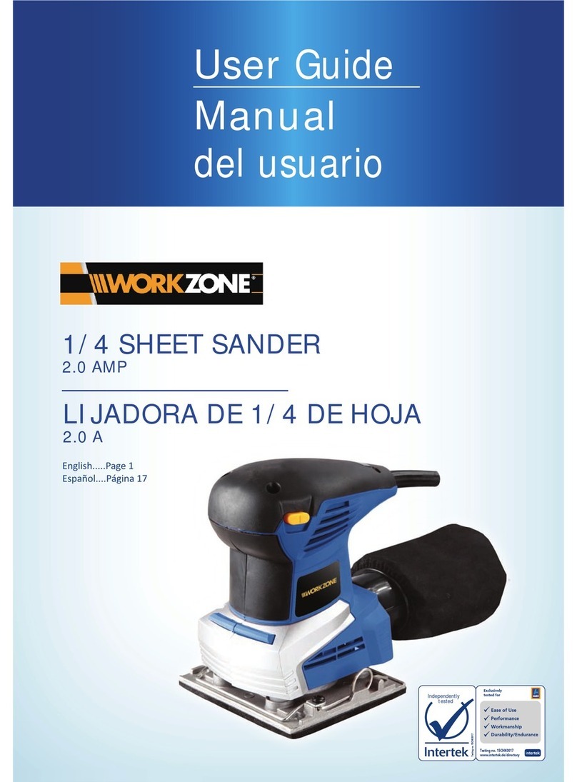
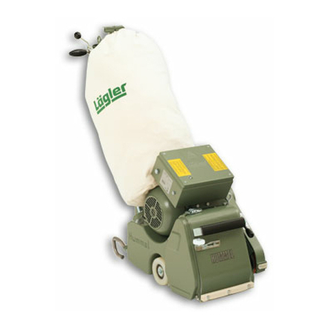
Lagler Flip User guide

EDGE-, CORNER- AND STAIR-SANDING MACHINE FLIP®
FLIP®
English / Englisch
Operation,
Maintenance, Safety
Translation of original operating instructions
for the edge-, corner- and stair-sanding machine
00.320.20.002 01.12.2012
*00.320.20.002*

FLIP®01.12.2012
English / Englisch
FLIP®- COMPONENTS
Dust bag
Rocker switch
Guide roller
Handle
Motor
Attachment
Fig. 1 Components of the edge-, corner- and stair-sanding machine FLIP®
Motor cable
Fan housing
Pipe socket with
locating flange
2

FLIP®01.12.2012
English / Englisch
1 Introduction....................................................................................................................................................................4
1.1 Features of the machine ...............................................................................................................................................4
1.2 Description of the machine ..........................................................................................................................................4
1.3 Proper use as intended.................................................................................................................................................4
1.4 Protective devices.........................................................................................................................................................5
2 Hazard warnings and safety instructions ...................................................................................................................5
2.1 Hazard warnings............................................................................................................................................................5
2.2 General safety instructions ..........................................................................................................................................8
3 Technical data..............................................................................................................................................................10
4 Commissioning.............................................................................................................................................................12
4.1 Preparing the machine................................................................................................................................................12
4.2 Connecting the power cable ......................................................................................................................................13
4.3 Starting the machine...................................................................................................................................................14
4.4 Switching off the machine..........................................................................................................................................15
5 Working with the FLIP®...............................................................................................................................................16
5.1 General application tips..............................................................................................................................................16
5.2 Replacing the sanding medium..................................................................................................................................17
5.3 Emptying the dust bag.................................................................................................................................................19
6 Transport and storage.................................................................................................................................................23
7 Maintenance work and replacement of wearing parts...........................................................................................24
7.1 Cleaning and care........................................................................................................................................................25
7.2 Tightening the V-belt ...................................................................................................................................................26
7.3 Replacing the V-belt....................................................................................................................................................27
7.4 Replacing the complete sanding plate......................................................................................................................29
7.5 Replacing the motor pulley.........................................................................................................................................30
7.6 Replacing the carbon brushes ...................................................................................................................................32
7.7 Checking the dust suction system.............................................................................................................................34
7.8 Adjusting the guide rollers .........................................................................................................................................35
7.9 Replacing the wheels and the guide rollers.............................................................................................................38
7.10 Adjusting the wall-protecting roller ..........................................................................................................................39
7.11 Replacing the wall-protecting roller .........................................................................................................................40
8 Regular inspection and maintenance work in accordance with accident prevention regulations ...................41
9 Causes of faults ...........................................................................................................................................................43
10 Circuit diagram.............................................................................................................................................................47
11 Spare parts...................................................................................................................................................................48
12 Service passport..........................................................................................................................................................59
13 EU Declaration of conformity .....................................................................................................................................60
CONTENTS
WARNING! Death, severe physical injury or significant property damage can occur if the cor-
responding cautionary measures are not taken.
CAUTION! Moderate to light physical injury or property damage can occur if the corresponding
cautionary measures are not taken.
ATTENTION! An undesired event can occur if the corresponding instructions are not followed.
3

FLIP®01.12.2012
English / Englisch
INTRODUCTION
1.1 FEATURES OF THE MACHINE
In figure 1 (page 2), we have indicated the most important com-
ponents of the FLIP®. Take your time to become familiar with the
machine.
1.2 DESCRIPTION OF THE MACHINE
The FLIP®edge-sanding machine works with a sanding plate on
which Velcro sanding discs can be fastened. Traditional sanding
discs fastened with a tension screw can, of course, also be used.
The work zone is protected by the attachment. The fan housing, on
which the electric motor is mounted in vertical position, is located
on the attachment. A motor power cable is used to connect the
machine to the power supply system. The motor switch with ON/OFF
positions is located on the switch box cover of the motor housing.
The machine is moved by means of two guide rollers at the rear
side of the machine. The handles are located on top of the motor. A
rotatable pipe socket is mounted on the rear of the fan housing which
feeds the sanding dust into the dust bag. The dust bag is connected
to the pipe socket via a flange with two quick-release fasteners. The
power cable is attached to the bag’s fixing bracket with Velcro tape
so that it is kept out of the working area of the machine.
There are three different attachments for the FLIP®(part numbers
are in Section 11, Spare parts):
• short attachment for sanding edges and stairs
• long attachment for sanding edges and below radiators or
similar objects
• attachment for sanding corners (corner attachment)
1.3 PROPER USE AS INTENDED
The FLIP®edge-sanding machine is suitable for the dry sanding of
wooden floors, cork floor and wooden stairs in the professional and
rental business sectors.
Any other form of use is not permitted without the approval of the
manufacturer!
Introduction
1
You have purchased a high-quality product
from LÄGLER®. We wish you a great deal
of success with your FLIP®. All LÄGLER®
products are subjected to a thorough
inspection before leaving the factory.
Please read these operating instructions
completely before you begin working with
your FLIP®. These operating instructions
include important information on
occupational safety and will provide you
with answers to many questions so that
you can work with the machine safely
and without any problems. If you cannot
find a specific subject in these operating
instructions, please read the LÄGLER®
application technique guidelines “Sanding
Wooden Floors” (http://www.laegler.com)
or contact our service department, your
retailer or your importer.
WARNING!
RISK OF DEATH from electrical shock:
The machine may never be used for wet
processing operations of any kind!
4

FLIP®01.12.2012
English / Englisch
HAZARD WARNINGS AND SAFETY INSTRUCTIONS
2.1 HAZARD WARNINGS
WARNING!
RISK OF DEATH from suffocation and RISK OF INJURY:
• Never wrap the power cable around your neck or other
parts of the body!
RISK OF DEATH from electrical shock:
• The machine may never be used for wet processing opera-
tions of any kind!
• Do not expose the machine to rain! Do not use the machine
in moist or wet environments!
• The machine must be switched off and the power plug must
be removed from the socket during all maintenance work and
work on the electrical equipment!
• Avoid body contact with grounded parts, e.g. pipes, radiators,
ovens, refrigerators!
• The quality of the motor cable and the power cable must
match the quality of the original LÄGLER®cable!
• The power cable must be protected from mechanical and/or
electrical damages in the workplace!
WARNING!
RISK OF DEATH, RISK OF INJURY, RISK OF
FIRE:
• Be certain to read the hazard warnings
and safety instructions before using the
machine!
• Instruct your coworkers and col-
leagues accordingly! Otherwise, these
persons could be exposed to danger or
injured!
ATTENTION!
• Keep these hazard warnings and safety
instructions in a safe place!
• Note the valid regulations and legal
conditions in your country!
Hazard warnings and safety instructions
2
1.4 PROTECTIVE DEVICES
The following parts of the machine are safety devices and thus must
always be kept in perfect condition:
Attachment cover, short/ = Dust protection, protection against
long V-belts
Attachment, short/long = Protection against sanding disc and
V-belts
Handle, motor housing, = Protection against current-carrying
switch box cover parts
2
5

FLIP®01.12.2012
English / Englisch
WARNING!
RISK OF DEATH from electrical shock:
• Do not carry or pull by the machine by the cable! Do not pull
on the cable to remove the plug from the socket! Protect the
cable against heat, oil and sharp edges!
RISK OF EXPLOSION due to sparks while sanding or a high dust
concentration in the air:
• Do not use the machine near
- sources of fires,
- flammable liquids or gases,
- potentially explosive areas!
• Do not smoke in a dusty environment, e.g. while sanding or
emptying the dust bag!
RISK OF FIRE from spontaneous combustion or from sparks while
sanding:
• There is a high risk of fire when sanding woods with a large
amount of resin, waxed floors or metal! Therefore, the ma-
chine must always be cleaned carefully directly after sanding.
Be certain to note the warning notices of the paint, oil and
wax manufacturers!
• Cloths, pads, et cetera which have been immersed in oil or wax
can spontaneously combust! Be certain to note the warning
notices of the paint, oil and wax manufacturers!
• The dust bag must always be removed from the machine af-
ter sanding and emptied into a waste bag with the emptying
fixture! Dispose of these waste bags in a non-combustible
container! Cover this container with a non-combustible cover
and be certain to store it and the dust bag outdoors ( Sec-
tion 5.3, Emptying the dust bag)!
RISK OF FIRE from the overheating of the cable.
• Only cables with wire cross-section of at least 1.5 mm² may
be used as motor cables and power cables!
HAZARD WARNINGS AND SAFETY INSTRUCTIONS
2
6

FLIP®01.12.2012
English / Englisch
WARNING!
HEALTH RISK CAUSED BY DUST:
• Make sure that the dust bag is properly fastened to the ma-
chine!
• If the machine is operated correctly, the mandatory dust emis-
sion values will not be exceeded! When emptying the dust
bag, it is advisable to wear a respiratory protective mask P3
(part number in Section 11, Spare parts)!
• Wear a respiratory protective mask of at least filter class P2
when conducting work that creates dust!
CAUTION!
RISK OF INJURY and RISK OF PROPERTY DAMAGE from rotating
tools and parts of the machine:
• Before turning on the machine, make sure that all tools and
adjustment tools have been removed from the machine!
• The machine may not be started if the sanding plate is on the
floor! Therefore, tip the machine backwards slightly to start
the machine ( Section 4.3, Starting the machine)!
• Do not reach into rotating tools or parts of the machine!
• Do not let children or other persons touch the machine or
cable and keep them out of the work area!
• Do not wear any long articles of clothing or jewellery! These
could be caught by moving parts!
RISK OF INJURY and RISK OF PROPERTY DAMAGE from uninten-
tional starting of the machine:
• The power plug must be removed from the socket when the
machine is switched off!
• Make sure that on/off switch is not set to on when connecting
the machine to the current supply!
RISK OF INJURY and RISK OF PROPERTY DAMAGE from the rolling
away, tipping or falling of the machine:
• The machine must be secured against rolling away, tipping
or falling when not in use!
Always ensure that the machine is standing firmly!
HAZARD WARNINGS AND SAFETY INSTRUCTIONS
2
7

FLIP®01.12.2012
English / Englisch
CAUTION!
RISK OF INJURY and RISK OF PROPERTY DAMAGE from unsuitable
parts:
• Only use tools, accessories and spare parts from LÄGLER®for
the FLIP®( Section 11, Spare parts)! There is no guarantee
for external parts or liability for damage caused by them!
HEALTH RISK caused by noise:
• Use hearing protection when conducting work that produces
noise!
RISK OF PROPERTY DAMAGE:
• Do not store the unused machine with sanding media on the
sanding plate! The sanding media can cause scratches on
the ground!
• Improper transport will result in damage to the machine!
2.2 GENERAL SAFETY INSTRUCTIONS
• Provide good illumination in the workplace!
Well lit construction sites reduce the risk of injury and allow
you to better evaluate the quality of your work.
• Keep your work area clean!
Untidy work area create a risk of accidents.
• Use the proper machines!
Do not use low-performance machines or additional devices
for heavy jobs. Do not use the machine for purposes and work
that it is not intended for.
• Do not overload the machine!
It works better and more safely in the power range noted.
• Do not bend too far over the machine!
Avoid unnatural postures. Make sure that you stay in a stable
position and keep your balance at all times.
• Be attentive!
Pay attention to your work. Work carefully and do not use the
machine if you are not concentrating.
HAZARD WARNINGS AND SAFETY INSTRUCTIONS
2
8

FLIP®01.12.2012
English / Englisch
• Maintain your machines with care!
Keep your machines clean so that you can work better and
more safely. Follow the maintenance guidelines and the
instructions for replacing tools. Regularly inspect the cable
and have it replaced by a qualified electrician if it is damaged.
Inspect the extension cable regularly and replace it if it is
damaged. Keep the handles dry and free of oil and grease.
• Check your machines for damage!
Before using the machines, you must inspect the safety
devices or damaged parts carefully to ensure that they are
working perfectly and as intended. Check whether the moving
parts are working properly, that they are not sticking, that no
parts are broken, whether all parts are in perfect condition
and installed properly and whether all other conditions which
could influence the operation of the machine are in order.
Damaged safety devices and parts must be properly repaired
or replaced by an authorized service shop insofar as nothing
to the contrary is indicated in the operating instructions.
Damaged switches must be replaced by a qualified
electrician. Do not use the machine if it cannot be started or
switched off by using its switch.
• Store your machines safely!
Store your unused machines in a dry, closed location out of
the reach of children!
HAZARD WARNINGS AND SAFETY INSTRUCTIONS
2
9

FLIP®01.12.2012
English / Englisch
TECHNICAL DATA
Technical data
Manufacturer....................................................... Eugen Lägler GmbH
Machine type..................................................edge-sanding machine
Serial number ................................................................see type plate
Year of manufacture .....................................................see type plate
Motor type .................................................................. universal motor
Voltage .......................................................................................... 230 V
Frequency ..................................................................... 50/60 Hz (CPS)
Output........................................................................................1.35 kW
Fuse protection...............................................................................10 A
Insulation class ................................................................................... F
Protection class ............................................................................IP 22
Protection system ............................................................................... 2
Safety devices......................................................no-voltage release,
thermal overload protection
Sanding disc diameter................................................150 mm (~ 5.9”)
Sanding disc diameter, corner attachment................61 mm (~ 2.4“)
Sanding disc speed under load ................. approx. 3100 1/min (rpm)
Sanding disc speed under load,
corner attachment .................................... approx. 7750 1/min (rpm)
Attachment height without wall-protecting roller.....44 mm (~ 1.7”)
Attachment height with wall-protecting roller ..........58 mm (~ 2.3”)
Corner attachment height ............................................51.5 mm (~ 2”)
Attachment length, short version..............................155 mm (~ 6.1”)
Attachment length, long version ............................. 315 mm (~ 12.4”)
Corner attachment length ..........................................225 mm (~ 8.9”)
Overall height without dust bag...............................460 mm (~ 18.1”)
Overall length without dust bag
- with short attachment.......................................... 460 mm (~ 18.1”)
- with long attachment............................................620 mm (~ 24.4”)
- with corner attachment .......................................530 mm (~ 20.9”)
Overall width..............................................................260 mm (~ 10.2”)
Total weight .................................................................9.8 kg (21.6 lbs)
Dust emissions at workplace.............< 0.2 mg/m³ (0.0024 gr./cu.yd.)
(measured as per the testing requirements GS-HO-15 of
German lumber industry professional association)
Workplace-related noise emission values..........................86 dB (A)
Measurement uncertainty constant of the
noise emission values...........................................................4 dB (A)
Vibration total value ahv ........................................................< 2.5 m/s²
(measured at the handle)
3
NOTE on noise emission:
The values indicated are emission values
and must not represent safe workplace
values as well.
Although a correlation exists between emis-
sion levels and immission levels, it is not
always possible to determine whether addi-
tional precautionary measures are required.
Factors that can have an effect on the
immission level existing at the workplace
include the duration of the effects, the
characteristics of the work area and other
sources of noise, e.g. the number of ma-
chines and processing operations in the
vicinity. The permissible workplace values
may also vary from country to country.
This information, however, is intended to
enable the user to better estimate the dan-
gers and risks.
NOTE:
The motor data indicated here refers to
machines used in the Federal Republic of
Germany. Exported machines may have
other data that can be seen on the motor
type plate.
10
FLIP®01.12.2012
English / Englisch
Application purposes
Dry edge-sanding, corner-sanding and stair-sanding of wood and
cork floors.
Basic equipment
Machine ready for use, dust bag, extension cable 3 x 1.5 mm² (length:
10 m), universal spanner, respiratory protective mask (P3), emptying
fixture, waste bag, cable tie and operating instructions.
Special accessories
Long attachment, corner attachment, foldable earmuff
Wearing parts
Please check the condition of the wearing parts mentioned below
at regular intervals in order to be able to work safely and optimally
at all times.
Replace the following in case of wear and/or damage:
• Extension cable
• Motor cable
• Rocker switch
• Velcro coating on the sanding plate
• V-belt
• Motor pulley
• Sanding plate, complete
• Dust bag
• Guide roller
• Paper tensioning disc
• Screw for paper tension
• Carbon brushes
TECHNICAL DATA
3
NOTE:
You will find the corresponding part number
for the special accessories and wearing
parts in Section 11, Spare parts.
WARNING!
RISK OF DEATH from electrical shock:
The machine may never be used for wet
processing operations of any kind!
11

FLIP®01.12.2012
English / Englisch
Fig. 3 Push the dust bag over the locating flange (1.) and
fix it in place with the two metal studs (2.).
4
Commissioning
The section describes how to start using the FLIP®on-site. In order
to prevent damage and malfunctions, you must proceed in the order
of steps indicated below.
4.1 PREPARING THE MACHINE
ATTENTION!
Please note that the packaging serves as a transport container
for the machine, accessories and the sanding medium. Fur-
thermore, the machine can be sent back safely in the original
packaging without risk should there be any problems.
1Unpack the machine carefully. Dispose of the packing materi-
als according to the environmental regulations.
2Pull out the stop bolt on the suction socket of the fan housing
(Fig. 2, 1.) and at the same time insert the pipe socket into the
fan housing (Fig. 2, 2.).
3Turn the pipe socket so that the opening of the elbow piece
is facing the back and the stop bolt can snap into place when
it is let go.
4The pipe socket can be turned 360°. Four fixed positions exist
where the stop bolt can snap into place in the pipe socket.
CAUTION!
RISK OF INJURY and RISK OF PROPERTY DAMAGE:
The stop bolt must always snap into place in the pipe socket!
5Push the dust bag opening over the locating flange to the
end of the elbow piece (Fig. 3, 1.). Fix the dust bag into place
using the two metal studs (Fig. 3, 2.).
Fig. 2 Pull the stop bolt (1.) and insert the pipe socket
into the fan housing (2.).
COMMISSIONING
12

FLIP®01.12.2012
English / Englisch
Fig. 4 Secure the dust bag using the quick-release
fasteners.
Fig. 5 Connect the motor cable to the extension cable.
6Attach the dust bag to the locating flange using the two quick-
release fasteners (Fig. 4).
4.2 CONNECTING THE POWER CABLE
1Insert the plug of the motor cable in the coupler of the exten-
sion cable (Fig. 5).
2Attach the extension cable coupler to the dust bag using the
Velcro loop (Fig. 6).
3Insert the extension cable into a sufficiently protected power
socket.
COMMISSIONING
4
Fig. 6 Attach the extension cable coupler to the dust
bag.
13

FLIP®01.12.2012
English / Englisch
4.3 STARTING THE MACHINE
CAUTION!
RISK OF INJURY and RISK OF PROPERTY DAMAGE from rotating
parts of the machine:
• Always tip the machine backwards slightly (Fig. 7) before
starting the machine so that the sanding disc is raised off
the floor!
• Never allow the machine to run unattended!
1Tip the machine backwards slightly (Fig. 7).
2Flip the rocker switch to “I” (Fig. 8, 1.). The switch button will
snap into the place and the motor will be started.
3 Tip the machine forward and begin sanding.
CAUTION!
RISK OF PROPERTY DAMAGE:
If the switch button does not snap into switch position “I”, do
not continue sanding! Otherwise the motor can be permanently
damaged!
Remedy the following causes for the malfunction:
• The electrical network has undervoltage! Use a transformer
if necessary.
• The extension cable is too long (longer than 20 m or the
cable cross-sections of the extension cable are smaller
than 1.5 mm²!
• The carbon brushes of the motor have reached their wear
limit and must be replaced ( Section 7.6, Replacing the
carbon brushes).
• The switch is defective! It must be replaced by a qualified
electrician (circuit diagram Section 10)!
COMMISSIONING
4
Fig. 8 Start (1.) and switch off (2.) the machine using the
rocker switch.
Fig. 7 Tilt the machine backwards slightly before starting
and switching off the machine.
14

FLIP®01.12.2012
English / Englisch
4.4 SWITCHING OFF THE MACHINE
CAUTION!
RISK OF INJURY and RISK OF PROPERTY DAMAGE from rotating
parts of the machine:
Always tip the machine backwards slightly (Fig. 7) before
switching off the machine so that the sanding disc is raised
off the floor!
1Tip the machine backwards slightly (Fig. 7).
2Flip the rocker switch to “O” (Fig. 8, 2.). The switch button will
snap into the place and the motor will be switched off.
3 Wait until the sanding plate comes to a complete stop before
stand the machine back on the sanding plate!
CAUTION!
RISK OF INJURY and RISK OF PROPERTY DAMAGE:
Always remove the power plug from the socket after you have
switched off the machine!
ATTENTION!
Do not store the unused machine with sanding media on the
sanding plate! The sanding media can cause scratches on the
ground!
COMMISSIONING
4
15

FLIP®01.12.2012
English / Englisch
WORKING WITH THE FLIP®
5.1 GENERAL APPLICATION TIPS
WARNING!
RISK OF DEATH from electrical shock:
The machine may never be used for wet processing opera-
tions of any kind!
ATTENTION!
• Bear in mind that the FLIP®operates at very high cutting
speeds! For this reason, there is a risk of burn marks for
finer grit grades!
• Do not apply excessive pressure to the attachment while
sanding! This will significantly worsen the sanding finish
by causing deep scratches or burn marks and could cause
the motor to switch off from overheating!
The FLIP®is a very versatile machine. The attachment can be
changed in a matter of seconds. The FLIP®is used for the sanding
of transitions, borders, edges, corners and stairs.
• Deep sanding marks due to the selection of a too coarse grit
grade can be prevented by starting the first sanding operation
with the finest grit grade possible.
• Prevent sanding marks made by previously used grit grade by
adhering to the order of the sandpaper grit grade and never
skip more than one grit grade.
• After replacing the sanding disc, start working in poorly lit
areas of the room in order to remove the initial aggressive-
ness of the sanding medium.
• Always vacuum the floor or stairs thoroughly before the first
sanding operation and after each additional one.
• Clean the wheels of the machine regularly.
Working with the FLIP®
Fig. 9 Guide the FLIP®with both hands.
5
NOTE:
For more information free of charge, please
contact: within Germany
- Telephone: 0800 / 52 34 537
- Fax: 0800 / 48 66 353
within the USA
- Telephone: 800-848-6635
or
- Telephone: 0049 - 7135 - 98 90 - 0
- Fax: 0049 - 7135 - 98 90 - 98
- e-mail: info@laegler.com
- Internet: http://www.laegler.com
You will also find important and interesting
application tips in the LÄGLER®application
technique guidelines “Sanding Wooden
Floors” (http://www.laegler.com)!
16

FLIP®01.12.2012
English / Englisch
Fig. 10 Remove the Velcro sanding disc from the sanding
plate.
5.2 REPLACING THE SANDING MEDIUM
ATTENTION!
• Only use sanding discs with paper as the base! Do not use
any sanding discs with thick bases such as fibre discs,
cutting discs or similar materials! Otherwise the sanding
plate will be damaged!
• Do not use any double sanding discs (with sanding grit on
both sides)! Otherwise the Velcro coating on the sanding
plate will be damaged!
• Always use only one sanding disc! Otherwise the sand-
ing results will not be satisfactory and the dust suction
system will not be fully operational!
• You will receive the best sanding finish and price/perfor-
mance ratio with the Velcro sanding discs from LÄGLER®!
Depending on the material being sanded, you will use various
sandpaper grit grades. Proceed as follows to change the sanding
medium:
5.2.1 VELCRO SANDING DISCS
1Switch off the machine.
2Pull the power plug out of the socket!
3Lay the machine on its side, avoiding damage to the floor and
the machine!
4Pull the worn-out Velcro sanding disc off of the sanding plate
(Fig. 10).
5Place a new Velcro sanding disc on the sanding plate. The
Velcro sanding disc must be positioned in the centre of the
sanding plate. The hole in the centre of the sanding disc and
the universal spanner make this step easier (Fig. 11).
6Press the Velcro sanding disc onto the sanding plate.
Fig. 11 Mount the new Velcro sanding disc in a centred
position and press down.
WORKING WITH THE FLIP®
5
17

FLIP®01.12.2012
English / Englisch
Fig. 12 Remove the screw with the universal spanner.
Fig. 13 Remove the screw and the paper tensioning disc
(1.) and remove the sanding disc (2.).
5.2.2 CONVENTIONAL SANDING DISCS
1Switch off the machine.
2Pull the power plug out of the socket!
3Lay the machine on its side, avoiding damage to the floor and
the machine!
4Use the universal spanner to remove the screw from the
sanding plate (Fig. 12).
5Remove the screw and paper tensioning disc (Fig. 13, 1.).
Remove the sanding disc from the sanding plate (Fig. 13, 2.)
and put all three parts aside.
6Put on a new sanding disc and insert the screw with the paper
tensioning disc into the hole of the sanding plate (Fig. 14, 1.).
7Turn the screw in the sanding plate with the universal spanner
(Fig. 14, 2.). Make sure that the sanding disc is as centred as
possible on the sanding plate.
8Tighten the screw with the universal spanner until it is hand-
tight.
ATTENTION!
Do not tighten the screw for attaching the sanding disc too
tightly! The thread of the sanding plate could otherwise be
damaged!
WORKING WITH THE FLIP®
5
Fig. 14 Mount the new sanding disc (1.) and tighten the
screw (2.).
18

FLIP®01.12.2012
English / Englisch
5.3 EMPTYING THE DUST BAG
WARNING!
RISK OF FIRE from the formation of sparks while sanding:
• The dust bag must always be removed from the machine
after sanding and emptied into a waste bag with the
emptying fixture! Dispose of these waste bags in a non-
combustible container!
Cover this container with a non-combustible cover and be
certain to store it and the dust bag outdoors (Fig. 27)!
• Note the warning on the motor housing (Fig. 15)!
HEALTH RISK caused by dust:
In order to ensure that the dust values in the air do not exceed
the prescribed threshold levels, please note:
•The dust must be emptied when it is one-third full at the
very latest in order to prevent a deterioration of the suction
performance due to the lack of filtering surface area! The
horizontal line on the outside of the dust bag marks the
maximum fill level!
•Do not work with an overfilled dust bag!
•Do not wash, patch or repair the dust bag in any other
manner!
•Damaged dust bags must be replaced with new ones!
•When emptying the dust bag, wearing a respiratory protec-
tive mask (at least filter class P2) is recommended!
In order to empty the dust bag in a manner as free from dust as pos-
sible, an emptying fixture, a waste bag and cable tie are included
with the FLIP®.
WORKING WITH THE FLIP®
5
Fig. 15 Note the warning on the motor housing!
19

FLIP®01.12.2012
English / Englisch
Fig. 18 Open both quick-release fasteners (1.) and remove
the dust bag (2.).
Fig. 16 Remove the coupler from the Velcro loop on the
dust bag.
Fig. 17 Shake the dust residue from the machine into the
dust bag.
Fig. 20 Pull the waste bag over the fixture.Fig. 19 Insert the waste bag into the emptying fixture.
Proceed as follows to empty the dust bag:
1 Switch off the machine.
2 Pull the power plug out of the socket!
3 Remove the extension cable coupler from the Velcro loop on
the dust bag (Fig. 16).
4Remove the plug of the motor cable from the extension cable
coupler.
5 Shake the dust residue from the machine into the dust bag
(Fig. 17).
6 Open the quick-release fasteners on the locating flange (Fig.
18, 1.).
7 Slowly pull the dust bag off of the locating flange (Fig. 18, 2.).
8 Hold the handle of the emptying fixture and insert a waste
bag from the ribbed side through the opening in the centre
of the fixture (Fig. 19).
9 Pull the waste bag over the emptying fixture from behind (Fig.
20).
WORKING WITH THE FLIP®
5
20
Other manuals for Flip
2
Table of contents
Other Lagler Sander manuals

Lagler
Lagler Flip User manual

Lagler
Lagler HUMMEL User manual

Lagler
Lagler UNICO User guide

Lagler
Lagler ELAN User manual

Lagler
Lagler Superhummel User guide

Lagler
Lagler HUMMEL User guide

Lagler
Lagler PROFIT Wiring diagram

Lagler
Lagler SINGLE User guide

Lagler
Lagler Flip User manual

Lagler
Lagler TRIO 900.65.00.100 User manual
Popular Sander manuals by other brands

Universal Tool
Universal Tool UT8749S-1 General Safety Information & Replacement Parts

MIRKA
MIRKA DEROS 650CV operating instructions

Parkside
Parkside PWP 90 A1 POLISHING MACHINE user manual

Black & Decker
Black & Decker 7448 instruction manual

Alpha tools
Alpha tools DS 180 operating instructions

Rupes
Rupes RH153A Operating and maintenance instruction