Lagler TRIO 900.65.00.100 User manual

THREE DISC SANDING MACHINE TRIO
English / Englisch
TRIO
www.laegler.com
00.900.20.002 01.04.2015
*00.900.20.002*
Operating Instructions
Translation of original operating instructions
for the three disc sanding machine

TRIO 01.04.2015
English / Englisch
CONTENTS
1 Introduction.....................................................................................................................................................................5
1.1 Features of the machine ................................................................................................................................................5
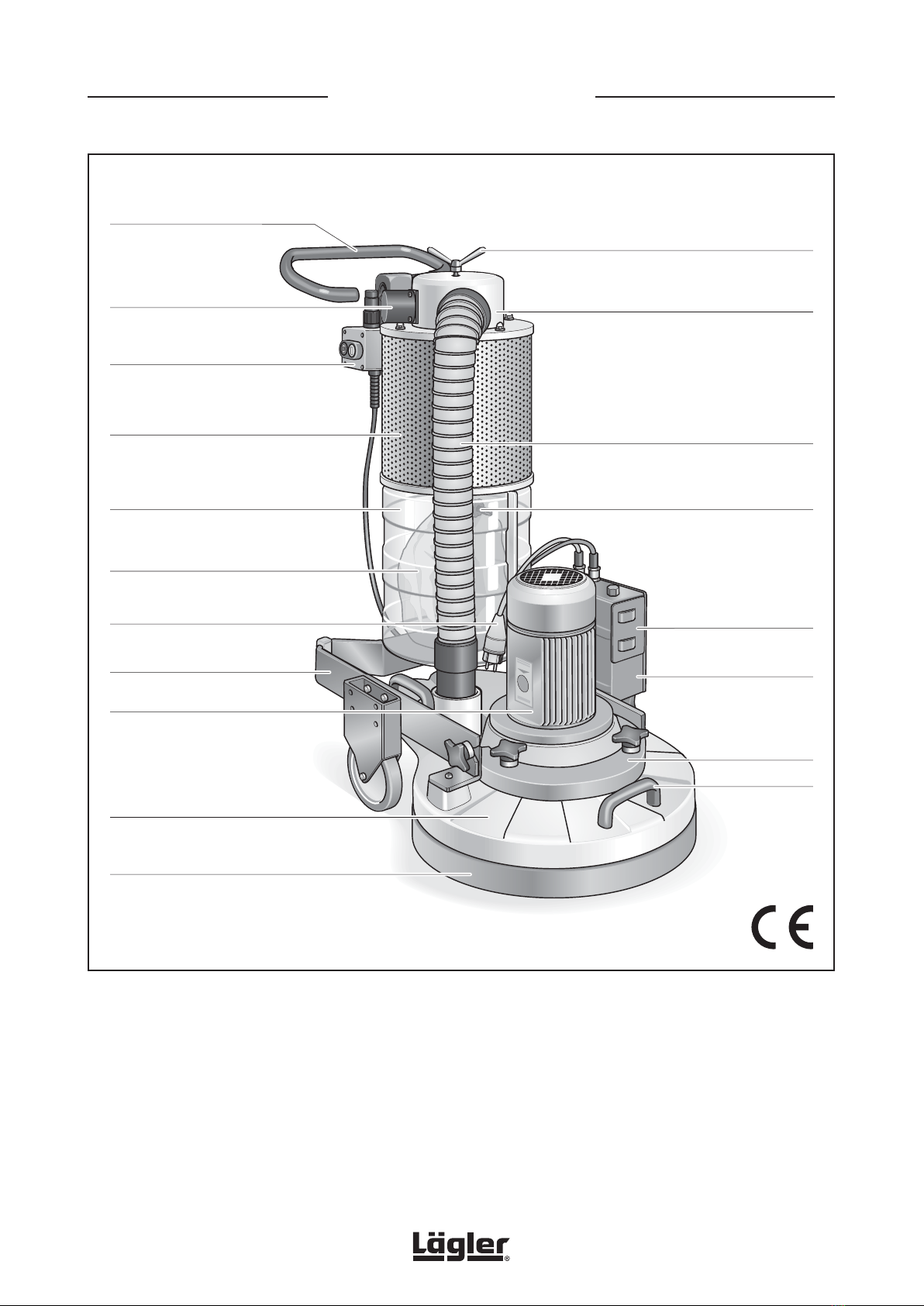
1.2 Description of the machine ...........................................................................................................................................5
1.3 Intended use of the machine.........................................................................................................................................6
1.4 Protective devices..........................................................................................................................................................6
1.5 Machine configuration...................................................................................................................................................7
1.5.1 Basic equipment...........................................................................................................................................................7
1.5.2 Optional equipment......................................................................................................................................................7
1.5.3 Wearing parts and safety-related parts ....................................................................................................................8
2 Hazard warnings and safety instructions ...................................................................................................................9
2.1 Hazard warnings.............................................................................................................................................................9
2.2 General safety instructions .........................................................................................................................................14
3 Technical data ..............................................................................................................................................................16
3.1 Data on type plate ........................................................................................................................................................16
3.2 Machine data................................................................................................................................................................17
4 Commissioning .............................................................................................................................................................19
4.1 Preparing the machine.................................................................................................................................................19
4.2 Connecting the power cable .......................................................................................................................................22
4.3 Switching on the machine...........................................................................................................................................23
4.4 Switching off the machine...........................................................................................................................................25
5 Working with the TRIO ................................................................................................................................................26
5.1 General information and tips.......................................................................................................................................26
5.2 Changing the sanding plates.......................................................................................................................................27
5.2.1 Removing the sanding plates....................................................................................................................................27
5.2.2 Mounting the sanding plates ....................................................................................................................................28
5.3 Changing the sanding media.......................................................................................................................................29
5.3.1 Changing the sanding discs......................................................................................................................................29
5.3.2 Conversion to sanding screens ................................................................................................................................30
5.3.3 Conversion to pads ....................................................................................................................................................30
5.4 Working with milling discs...........................................................................................................................................31
5.5 Changing the dust bag .................................................................................................................................................33
6 Transport and storage..................................................................................................................................................35
6.1 Dismantling the machine before transportation .......................................................................................................35
6.2 Reassembly after transportation ................................................................................................................................37
6.3 Storage ..........................................................................................................................................................................38
7 Maintenance work and replacement of wearing parts ..........................................................................................39
7.1 Cleaning and care.........................................................................................................................................................40
7.2 Cleaning the filter cartridge ........................................................................................................................................41
7.3 Changing the filter cartridge .......................................................................................................................................42
7.3.1 Removing the filter cartridge ....................................................................................................................................42
7.3.2 Mounting the filter cartridge.....................................................................................................................................43
7.4 Changing the tooth belt................................................................................................................................................45
7.4.1 Removing the tooth belt.............................................................................................................................................45
7.4.2 Mounting the tooth belt .............................................................................................................................................46
2

TRIO 01.04.2015
English / Englisch
CONTENTS
7.5 Changing the V-belt......................................................................................................................................................48
7.5.1 Removing the V-belt...................................................................................................................................................48
7.5.2 Mounting the V-belt ...................................................................................................................................................50
7.6 Changing the sealing felt on the cover of the inner housing...................................................................................52
7.7 Changing the rubber plugs of the sanding plate pulleys..........................................................................................53
8 Regular inspection and maintenance work in accordance with accident prevention regulations .................54
9 Causes of faults............................................................................................................................................................56
9.1 The machine does not run or has switched off automatically.................................................................................56
9.2 The machine attempts to start up but is not able to do so.......................................................................................57
9.3 The machine runs but has no or very little sanding power capacity......................................................................58
9.4 The machine vibrates intensely and runs noisily......................................................................................................59
9.5 The machine runs but creates a great deal of dust..................................................................................................60
9.6 Sanding problems (waves, strips, grooves)...............................................................................................................61
10 Circuit diagrams...........................................................................................................................................................64
11 Spare parts TRIO ..........................................................................................................................................................66
12 Service passport ..........................................................................................................................................................79
13 EU Declaration of conformity for machines (EU Directive 2006/42/EC).................................................................80
Safety notes used in this operating instructions and their meaning:
WARNING! Death, severe physical injury or significant property damage can occur if the
corresponding cautionary measures are not taken!
CAUTION! Moderate to light physical injury or property damage can occur if the corresponding
cautionary measures are not taken!
ATTENTION! An undesired event can occur if the corresponding instructions are not followed!
3

TRIO 01.04.2015
English / Englisch
TRIO - MAIN COMPONENTS
Wing nut of cleaning slide
Dust separator
Suction hose
Fig. 1 Main components of the three disc sanding machine TRIO.
Handle
Pressure control
sensor
On/off switch
Dust bag box
Chassis
Motor cable
Filter housing
Switch box
Handle
MultiClip for fastening the dust bag
Motor
Sanding unit
Velcro sealing tape
Disposable dust bag
Transport holder
for switch
Additional weight
4

TRIO 01.04.2015
English / Englisch
INTRODUCTION
1.1 FEATURES OF THE MACHINE
Figure 1 depicts the TRIO with the main components designated.
Take your time to become familiar with the machine.
1.2 DESCRIPTION OF THE MACHINE
The TRIO works with three sanding discs that are suspended in a
freely rotating support. The working area is fully covered by the
machine housing.
The motor and switch box are positioned vertically on the machine
housing. One of the cables leads to the power supply, the other to
the on/off switch which can be positioned either on the switch box
or below the guide handle.
The chassis consisting of the frame with guide tube, wheels and
adjustable handle is mounted to the sanding unit with two cross
grip fasteners and can be removed for transport purposes.
A dust separator is fixed to the chassis and connected to the
dust suction system of the sanding unit by a flexible suction hose.
Dust is separated by a coarse filter system and collected in the
disposable dust bag.
Inside the dust bag box the dust bag is fastened to the dust
separator with a MultiClip. The transparent dust bag box can be
opened using two fasteners.
The air coming from the dust separator passes through a fine
particle filter behind the perforated cover before being blown
out into the environment. A sensor checks the air-pressure in the
dust separator and a red warning lamp lights up when the suction
capacity is too low.
To return to the correct suction capacity, the cleaning slide must
be used to clean the fine particle filter.
Introduction
1
You have purchased a high-quality product
from LÄGLER®. We wish you a great deal
of success with your TRIO. All LÄGLER®
products are subjected to a thorough
inspection before leaving the factory.
Read these operating instructions
completely before working with the
TRIO for the first time! These operating
instructions include important information
on occupational safety and will provide
you with answers to many questions
so that you can work with the machine
safely and without any problems. If you
cannot find a specific subject in these
operating instructions, please read
the LÄGLER®application technique
manual “Sanding of wooden floors”
(http://www.laegler.com) or contact our
service department, your retailer or your
importer.
5

TRIO 01.04.2015
English / Englisch
INTRODUCTION
1.3 INTENDED USE OF THE MACHINE
The three disc sanding machine TRIO is suitable for dry sanding
of wooden floors or cork floors in a dry environment. Additional
milling discs are available for dry work on screed or other subfloors.
Application fields
• wooden floor finishing
• intermediate varnish sanding
• refurbishing of engineered flooring
• sanding of cork floors, screeds and fillers
• subfloor treatment
• removing of dirt, glue, carpet back and felt board residues
• application of cleaning agents, polish and cold wax
• dry polishing of surfaces
Any other form of use is not permitted without the approval of the
manufacturer!
1.4 PROTECTIVE DEVICES
The following parts of the machine are protective devices and thus
must always be kept in perfect condition:
machine housing = protection against tools and rotating parts
dust separator = protection of filter cartridge,
protection against dust
dust bag box = dust bag protection
Velcro sealing tape = protection against dust
switch box = protection against current-carrying parts
1
WARNING!
RISK OF DEATH from electrical shock:
The machine may never be used for wet
processing operations of any kind!
6

TRIO 01.04.2015
English / Englisch
INTRODUCTION
1.5 MACHINE CONFIGURATION
1.5.1 BASIC EQUIPMENT
• 1 machine ready for operation
• 1 operating instructions
• 3 sanding plates for Velcro discs, sanding screen and pads
• 1 additional weight 9 kg (20 lbs)
• 25 dust bags
• 1 MultiClip for fastening the dust bag
• 1 extension cable, length 10 m (394”):
for single-phase AC motor 3 x 2.5 mm² (3 x 0.0039 sq.in.)
for three-phase AC motor 5 x 1.5 mm² (5 x 0.0023 sq.in.)
• 1 O-ring as a strain relief device
• 1 tool bag
• 1 Torx screwdriver T15
• 1 Torx screwdriver T30
• 1 closed mouth wrench, size 10/13 mm
• 2 open mouth wrench, size 17 mm
• 1 hexagonal socket wrench, size 4 mm
• 1 hexagonal socket wrench, size 5 mm
• 1 hexagonal socket wrench, size 6 mm
• 1 cotton bag
• 10 plastic pins
• 3 normal pads
• 3 sanding screens grit 60
1.5.2 OPTIONAL EQUIPMENT
• 3 milling discs with 3 indexable inserts each
• cable support bracket
• cable support with O-ring as a strain relief device
• foldable earmuff
• respiratory protection mask, filter class P3
• safety switch for fault current PRCD-S (for German mains
supply)
1
NOTE:
You will find the corresponding part
numbers for the optional equipment and
wearing parts in Section 11, Spare parts
TRIO.
7

TRIO 01.04.2015
English / Englisch
1.5.3 WEARING PARTS AND SAFETY-RELATED PARTS
Check the condition of the wearing parts and safety-related parts
mentioned below at regular intervals in order to be able to work
safely and optimally at all times.
Replace the following parts in case of wear and/or damage:
• extension cable
• motor cable
• on/off switch
• Velcro sealing tape on machine housing
• MultiClip
• filter cartridge in dust separator
• pressure control sensor
• V-belt
• motor pulley
• V-belt tensioner
• tooth belt
• tooth belt tensioner
• rubber plugs of sanding plate pulleys
• sealing felt on cover of inner housing
• flexible Velcro ring of sanding plate
• wheels
INTRODUCTION
1
8

TRIO 01.04.2015
English / Englisch
HAZARD WARNINGS AND SAFETY INSTRUCTIONS
WARNING!
RISK OF DEATH, RISK OF INJURY, RISK
OF FIRE:
•Be certain to read the hazard warnings
and safety instructions before using
the machine!
•Instruct your coworkers and col-
leagues accordingly! Otherwise these
persons could be exposed to danger
or injured!
•Keep these hazard warnings and
safety instructions in a safe place!
•Observe the applicable regulations
and legal requirements in your coun-
try!
Hazard warnings and safety instructions
2
2.1 HAZARD WARNINGS
WARNING!
RISK OF DEATH from suffocation and RISK OF INJURY:
• Never wrap the power cable around your neck or other parts
of the body!
RISK OF DEATH from electrical shock:
• The machine may never be used for wet processing
operations of any kind!
• Do not expose the machine to rain! Do not use the machine
in moist or wet environments!
• Never connect the machine to hazardous electrical power
sources! Only use safety sockets!
• To protect yourself and the machine against faults in the
mains supply use a safety switch (for German mains supply
part number in Section 11, Spare parts TRIO)!
Observe the applicable regulations and legal requirements
in your country!
• All extensive maintenance work, especially on the electrical
equipment, must be conducted by a qualified expert for safety
reasons!
• The machine must be switched off and the power plug must
be removed from the socket during all maintenance work
and work on the electrical equipment!
• Avoid body contact with grounded parts, e.g. pipes, radiators,
ovens, refrigerators!
• The quality of the motor cable and the power cables must
match the quality of the original LÄGLER®cables!
• The motor cable and the power cables must be protected
from mechanical and electrical damages in the workplace!
• Do not carry or pull by the machine by the cable! Do not pull
on the cable to remove the plug from the socket! Protect the
cables against heat, oil and sharp edges!
9

TRIO 01.04.2015
English / Englisch
2
HAZARD WARNINGS AND SAFETY INSTRUCTIONS
RISK OF DEATH from unsecured load:
• When transported in a car or the like, the machines and all
parts must be secured against sliding!
RISK OF EXPLOSION due to sparks while sanding or a high dust
concentration in the air:
• Do not use the machine near
- sources of fires,
- flammable liquids or gases,
- potentially explosive areas!
• Do not smoke in a dusty environment, e.g. while sanding,
changing the dust bag or cleaning the machine!
RISK OF FIRE from sparks while sanding or from spontaneous
combustion:
• Prior to sanding a nailed or screwed floor all nails or screws
must be countersunk deeply enough so that they cannot be
sanded:
- Countersink the nails for example with a hammer and a
punch!
- Tighten the screws!
• There is a high risk of fire when sanding woods with a large
amount of resin, oiled or waxed floors or metal! Therefore,
the machine must always be cleaned carefully directly
after sanding! Be certain to note the warning notices of the
manufacturers of paint, oil and wax!
• Cloths, pads, et cetera which have been immersed in oil or
wax can spontaneously combust! Be certain to note the
warning notices of the manufacturers of paint, oil and wax!
• The dust bag must always be removed from the machine
directly after sanding! Seal and dispose the dust bags in
a non-combustible container! Cover this container with a
non-combustible cover ( Section 5.5, Changing the dust
bag)!
• Always transport and store the machine without dust bag!
WARNING!
10

TRIO 01.04.2015
English / Englisch
2
HAZARD WARNINGS AND SAFETY INSTRUCTIONS
RISK OF FIRE from the overheating of the cable.
• Only the following motor cables and power cables may be
used:
- Machines with motor for mains voltage 220 V or 230 V:
Cables with three wires and wire cross-sections of at least
2.5 mm² (0.0039 sq.in.)!
- Machines with motor for mains voltage 400 V:
Cables with five wires and wire cross-sections of at least
1.5 mm² (0.0023 sq.in.)!
• The maximum cable length in order to connect the machine
to the mains supply must not exceed 20 m (790”)!
HEALTH RISK caused by dust:
• Make sure that the dust bag is properly fastened to the
machine!
• Note that each dust bag can only be used once!
• Do not use damaged or repaired dust bags! Damaged dust
bags must be replaced with new ones!
• Do not work with an overfilled dust bag ( Section 5.5,
Changing the dust bag)!
• Never work with the wing nut and cleaning slide of the
dust separator pulled up, and observe the filter cleaning
instructions to prevent clogging of the filter cartridge/dust
separator. Clogging can otherwise make troublesome and
time-consuming cleaning work necessary.
• If the machine is operated correctly, the mandatory dust
emission values will not be exceeded! As long as you change
the disposable dust bag with great care and according to the
instructions printed on the dust bag, you are not required to
wear a respiratory protective mask!
• A respiratory protective mask (at least filter class P2) must
be worn when conducting other work that creates dust, e.g.
cleaning of the machine!
WARNING!
11

TRIO 01.04.2015
English / Englisch
2
HAZARD WARNINGS AND SAFETY INSTRUCTIONS
RISK OF INJURY and RISK OF PROPERTY DAMAGE from rotating
tools and parts of the machine:
• For all operating conditions of the machine only one operator
is required. As a consequence, for safety reasons only one
person must be in the working area while operating the
machine!
• Before switching on the machine, make sure that
- all wrenches and adjustment tools have been removed from
the machine,
- the sanding plates or milling discs are in place correctly!
• The machine must not be switched on in a tilted position!
• Never leave the operational machine unattended!
• Do not reach into rotating tools or parts of the machine!
• Do not let children or other persons touch the machine or
cables and keep them out of the work area!
• Do not wear any long articles of clothing or jewellery! These
could be caught by moving parts!
RISK OF INJURY and RISK OF PROPERTY DAMAGE from uninten-
tional starting of the machine:
• The power plug must always be removed from the socket
when the machine is switched off!
• Make sure that on/off switch is not set to ON when connecting
the machine to the mains supply!
RISK OF INJURY and RISK OF PROPERTY DAMAGE from the rolling
away, tipping or falling of the machine:
• The machine must be secured against rolling away, tipping
or falling when not in use!
• Always ensure that the machine is standing securely!
RISK OF INJURY and RISK OF PROPERTY DAMAGE from unsuit-
able parts:
• Only use tools, accessories and spare parts from LÄGLER®
for the TRIO (part numbers in Section 11, Spare parts TRIO)!
Warranty claims for foreign parts or damage caused thereby
cannot be accepted!
CAUTION!
12

TRIO 01.04.2015
English / Englisch
2
HAZARD WARNINGS AND SAFETY INSTRUCTIONS
HEALTH RISK caused by noise:
• Use hearing protection when conducting work that produces
noise! Observe the applicable regulations and legal
requirements in your country!
RISK OF PROPERTY DAMAGE:
• Remove the sanding plates and milling discs from the machine
when the machine is not to be used, because otherwise
- the sanding media or milling discs can cause scratches on
the ground,
- the machine weight can damage the flexible Velcro rings
of sanding plates or the indexable inserts of milling discs!
• Never conduct a maintenance or a replacement of wearing
parts on the newly sanded wooden floor! Thus, you will avoid
scratches or other damage to the floor!
• Never use any cleaning products which contain solvents!
• Never blow compressed air into the dust separator as
otherwise the highly sensitive pressure control sensor could
be damaged!
• Improper transport will result in damage to the machine!
CAUTION!
13

TRIO 01.04.2015
English / Englisch
2
HAZARD WARNINGS AND SAFETY INSTRUCTIONS
2.2 GENERAL SAFETY INSTRUCTIONS
• Check your machines for damage!
Before using the machines, you must inspect the safety
devices carefully to ensure that they are working perfectly
and as intended.
Check whether the moving parts are working properly, that
they are not sticking, that no parts are broken, whether all
parts are in perfect condition and installed properly and
whether all other conditions which could influence the
operation of the machine are in order.
Damaged safety devices and parts must be properly repaired
or replaced by an authorized service shop insofar as nothing
to the contrary is indicated in the operating instructions.
Regularly inspect the motor cable and have it replaced by
a qualified electrician if it is damaged. Inspect the extension
cable regularly and replace it if it is damaged (part numbers
in Section 11, Spare parts TRIO).
Damaged electrical components must be replaced by a
qualified electrician (part numbers in Section 11, Spare parts
TRIO).
Do not use the machine if it cannot be switched on and/or
switched off by using its switch.
• Maintain your machines with care!
- Keep your machines clean so that you can work better and
more safely.
- Follow the maintenance guidelines and the instructions for
replacing tools.
- Keep the handles dry and free of oil and grease.
• Provide good illumination in the workplace!
Well lit construction sites reduce the risk of injury and allow
you to better evaluate the quality of your work.
• Keep your work area tidy!
Untidy work areas create a risk of accidents.
• Use the proper machines!
Do not use low-performance machines or additional devices
for heavy jobs. Do not use the machine for purposes and work
that it is not intended for.
14

TRIO 01.04.2015
English / Englisch
2
HAZARD WARNINGS AND SAFETY INSTRUCTIONS
• Do not overload the machines!
It works better and more safely in the power range noted.
• Do not bend too far over the machine!
Avoid unnatural postures. Make sure that you stay in a stable
position and keep your balance at all times.
• Be attentive!
Pay attention to your work. Work carefully and do not use
the machines if you are not concentrating.
• Store your machines safely!
Store your unused machines in a dry, closed location out of
the reach of children!
15

TRIO 01.04.2015
English / Englisch
TECHNICAL DATA
3.1 DATA ON TYPE PLATE
ATTENTION!
In order to receive the correct spare parts from us, please
specify in inquiries and spare part orders always the serial
numbers of your machines!
The type plate is located on the switch box of motor (fig. 2). The
following technical data are specified on the type plate (fig. 3):
1Manufacturer
2Serial number of machine (Mach.-No.)
3Year of manufacture (Year)
4Machine name (Type)
5Required mains voltage in volt (V)
6Current consumption in ampere (A)
7Motor frequency in CPS (Hz)
8Motor power in kilowatt (KW)
9Motor speed in 1/min (Rpm)
10 Power factor cos phi (cos)
11 Insulation class (Insul. Cl.)
12 Protection class (Prot. Cl.)
13 Type of current
14 Country of manufacture
Made in Germany
XXXXX-XX
12345
Insul.Cl. Prot.Cl. Type of Current
F IP54 AC
V A Hz KW Rpm cos
XXX XX XX XX XXXX 0.XX
Type
TRIO
Mach.-No. Year
XXXXX-XX XXXX
Fußbodenschleifmaschine
Kappelrain 2
D-74363 Güglingen-Frauenzimmern
Tel. +49 7135 98900 www.laegler.com
Eugen Lägler GmbH
14
13
1
2 3 4
5 6 7 8 9 10
11 12
2
Technical data
Fig. 2 Type plate on switch box of motor.
Fig. 3 Data on type plate.
3
16

TRIO 01.04.2015
English / Englisch
TECHNICAL DATA
3.2 MACHINE DATA
Manufacturer Eugen Lägler GmbH
Machine type three disc
sanding machine
Machine name TRIO
Serial number see type plate (fig. 2)
Year of manufacture see type plate (fig. 2)
Motor type single-phase AC motor
Voltage 230 V 220 V
Frequency 50 Hz
(CPS)
60 Hz
(CPS)
60 Hz
(CPS)
Motor power 1.8 kW
Running capacitor 40 µF
Motor type three-phase AC motor
Voltage 400 V
Frequency 50 Hz
Motor power 2.2 kW
Necessary fuse of mains supply at least 16 A
Insulation class F
Protection class IP 54
Safety devices
no-voltage release,
temperature switch as
overload protection in
the motor
Diameter of sanding plate / milling
disc 200 mm (approx. 7.9“)
Speed of sanding plate / milling
disc
- machine with motor 50 Hz (CPS)
- machine with motor 60 Hz (CPS)
approx. 600 1/min (rpm)
approx. 720 1/min (rpm)
Overall length of machine 870 mm (approx. 34.3“)
Overall width of machine 490 mm (approx. 19.3“)
Overall height of machine 990 mm (approx. 39“)
Weight of sanding unit 54 kg (approx. 119 lbs)
Weight of chassis with dust
separator 24 kg (approx. 53 lbs)
Overall weight of machine 78 kg (approx. 172 lbs)
Additional weight 9 kg (approx. 20 lbs)
Filter dimension 1.43 m²
(approx. 15.4 sq. ft.)
Filter class M
3
17

TRIO 01.04.2015
English / Englisch
NOTE on noise emission:
The values indicated are emission values
and must not represent safe workplace
values as well.
Although a correlation exists between
emission levels and immission levels, it is
not always possible to determine whether
additional precautionary measures are
required.
Factors that can have an effect on the
immission level existing at the workplace
include the duration of the effects, the
characteristics of the work area and
other sources of noise, e.g. the number of
machines and processing operations in the
vicinity. The permissible workplace values
may also vary from country to country.
This information, however, is intended
to enable the user to better estimate the
dangers and risks.
TECHNICAL DATA
3
Running time after shut off < 5 sec.
Dust emissions at workplace
(measured as per the testing
requirements GS-HO-15 of German
Social Accident Insurance DGUV)
< 0.2 mg/m³
(0.0024 gr./cu.yd.)
Workplace-related noise emission
values, measurement taken 1.6 m
(5.25 ft.) above floor
- sanding of beech parquet with
sanding disc grit 80
- removal of glue residue using
milling discs
80 dB(A)
80 dB(A)
Measurement uncertainty
constant of the noise emission
values
4 dB(A)
Vibration total value ahv
(measured at the handle) < 2.5 m/s²
18

TRIO 01.04.2015
English / Englisch
This paragraph contains instructions on how to put your TRIO
machine into operation at the workplace. In order to prevent
damage and malfunctions it is necessary to strictly stick to the
sequence of steps indicated below.
CAUTION!
RISK OF INJURY and RISK OF PROPERTY DAMAGE:
Before working with the machine for the first time, operating
staff must be adequately instructed!
4.1 PREPARING THE MACHINE
ATTENTION!
To ensure safe dispatch of the machine, the packaging should
be used for transport purposes!
1Unpack the machine carefully. Take care to deposit the
packaging materials that are no longer required in an
environmentally-friendly way.
2After unpacking the machine, release the clamping lever of
the handle (fig. 4, 1), press the handle forward (fig. 4, 2) and
pull the clamping lever back into its prior position (fig. 4, 3).
3While holding on to the handle, carefully tilt the machine
backwards into a horizontal position (fig. 5). Make sure that
the machine gets to rest on the guide tube (fig. 6, A) and the
two protective rubbers (fig. 6, B). Make sure the machine is
in a safe position! Now the sanding plates are accessible
from the front.
COMMISSIONING
Commissioning
Fig. 4 To tilt the machine, release the clamping lever
of the handle (1), press the handle forward (2)
and pull the clamping lever back into its prior
position (3).
Fig. 6 Make sure that the machine gets to rest on the
guide tube (A) and the two protective rubbers (B).
Make sure the machine is in a safe position!
4
Fig. 5 Carefully tilt the machine backwards.
19

TRIO 01.04.2015
English / Englisch
COMMISSIONING
4 The changing of sanding media is described in:
- Section 5.3.1, Changing the sanding discs
- Section 5.3.2, Conversion to sanding screens
- Section 5.3.3, Conversion to pads
In order to work with milling discs please proceed as
described in Section 5.4, Working with milling discs.
CAUTION!
RISK OF INJURY and RISK OF PROPERTY DAMAGE:
• Make sure the sanding plates are in place correctly! They
must fit tightly on the bearing and slide into place with a
perceptible click!
•Always use three sanding plates of the same type!
5Bring the machine back into vertical position so that the
sanding plates are resting flat on floor surface (fig. 7).
6Release the clamping lever of the handle (fig. 8, 1), adjust
the handle height to your convenience (fig. 8, 2) and pull the
clamping lever back into its prior position (fig. 8, 3).
7Open the dust bag box by turning the two fasteners upwards
(fig. 9, 1) and open up the movable half of the dust bag box
(fig. 9, 2).
8Check to make sure the dust bag is placed correctly on the
neck of dust separator (fig. 10, A). The side of the dust bag
with the print on it must be facing you (fig. 10, B).
4
Fig. 8 Release the clamping lever of the handle (1), adjust
the handle height to your convenience (2) and pull
the clamping lever back into its prior position (3).
Fig. 7 Bring the machine back into vertical position.
Fig. 9 Open the dust bag box by turning the two fasteners
upwards (1) and open up the movable half of the
dust bag box (2).
Fig. 10 Check to make sure the dust bag is placed
correctly on the neck of dust separator (A). The
side of the dust bag with the print on it must be
facing you (B).
20
This manual suits for next models
3
Table of contents
Other Lagler Sander manuals

Lagler
Lagler Flip User guide

Lagler
Lagler SINGLE User manual

Lagler
Lagler SINGLE User guide

Lagler
Lagler Superhummel User guide

Lagler
Lagler ELAN User guide

Lagler
Lagler UNICO User manual

Lagler
Lagler Flip User manual

Lagler
Lagler Flip User manual

Lagler
Lagler PROFIT Wiring diagram

Lagler
Lagler Trio User guide