-5-www.igmtools.com
• Keep children away. All visitors should be kept
at a safe distance from the work area.
• Make your workshop kid proof with padlocks,
master switches, or by removing starter keys.
• Don‘t force tool. It will do the job better and
safer at the rate for which it was designed.
• Use right tool. Don‘t force tool or attachment
to do a job for which it was not designed.
• Use proper extension cord. Make sure your
extension cord is in good condition. When using
an extension cord, be sure to use one heavy
enough to carry the current your product will
draw. An undersized cord will cause a drop
in line voltage resulting in loss of power and
overheating.
• Wear proper apparel do not wear loose
clothing, gloves, neckties, rings, bracelets, or
other jewellery which may get caught in moving
parts. Non-slip footwear is recommended. Wear
protective hair covering to contain long hair.
• Always use safety glasses. Also use a face
or dust mask if cutting operation is dusty.
Everyday eyeglasses only have impact resistant
lenses, they are not safety glasses.
• Secure work. Use clamps or a vice to hold the
work when practical. It‘s safer than using your
hand and it frees both hands to operate the tool.
• Don‘t overreach. Keep proper footing and
balance at all times.
• Maintain tools with care. Keep tools sharp
and clean for best and safest performance.
Follow instructions for lubricating and changing
accessories.
• Disconnect tools before servicing and when
changing accessories, such as blades, bits,
cutters, and the like.
• Reduce the risk of unintentional starting. Make
sure power switch is in the o position before
plugging the machine in.
• Use recommended accessories. Consult the
owner‘s manual for recommended accessories.
The use of improper accessories may cause
risk of injury to persons.
• Never stand on tool serious injury could
occur if the tool is tipped or if the cutting tool is
unintentionally contacted.
• Check damaged parts. Before further use of
the tool, a guard or other part that is damaged
should be carefully checked to determine that
it will operate properly and perform its intended
function - check for alignment of moving parts,
binding of moving parts, breakage of parts,
mounting, and any other conditions that may
aect its operation. A guard or other part that
is damaged should be properly repaired or
replaced.
• Direction of feed. Feed work into a blade or
cutter against the direction of rotation of the
blade or cutter only.
• Never leave tool running unattended. Turn
power o. Don‘t leave tool until it comes to a
complete stop.
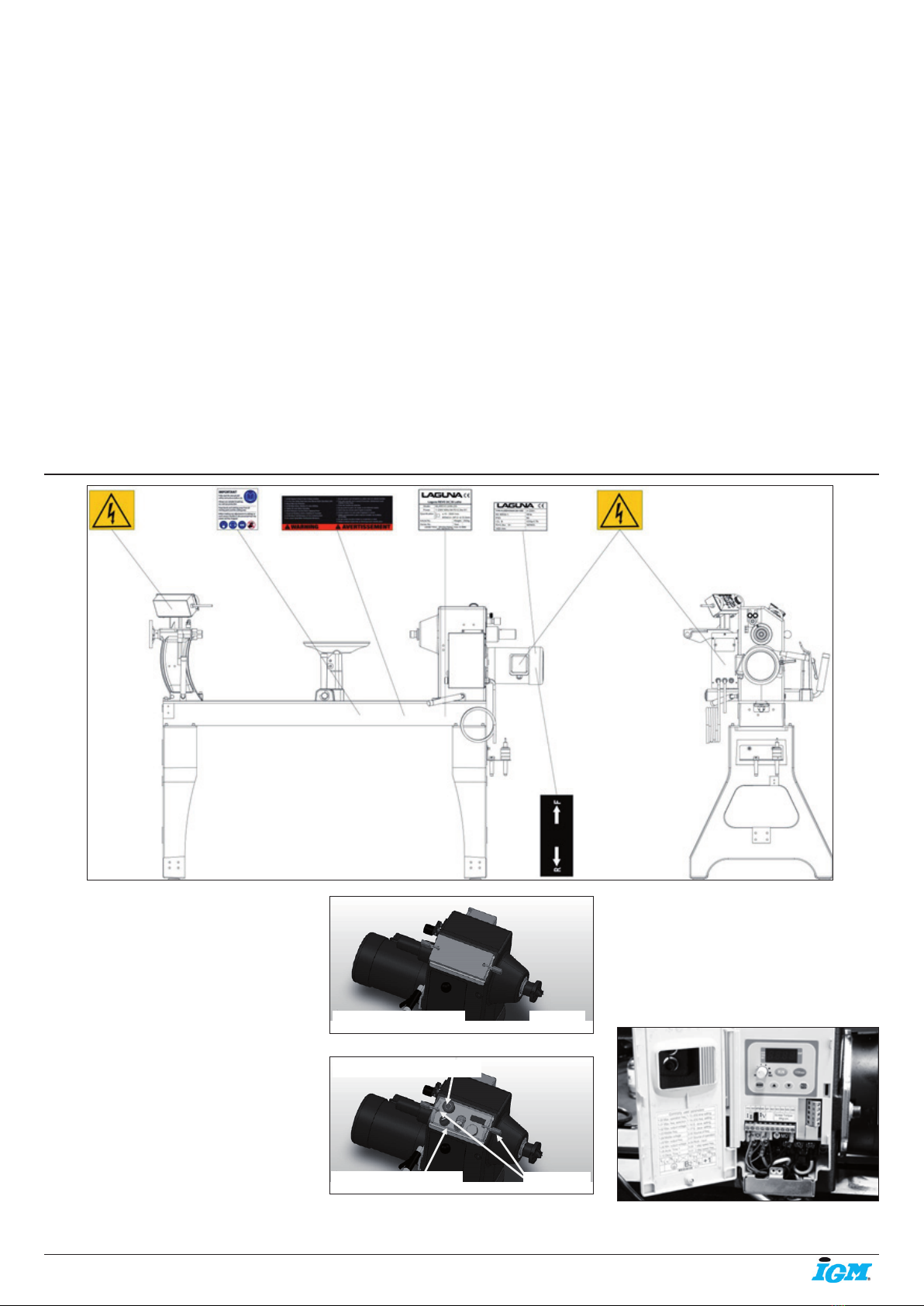
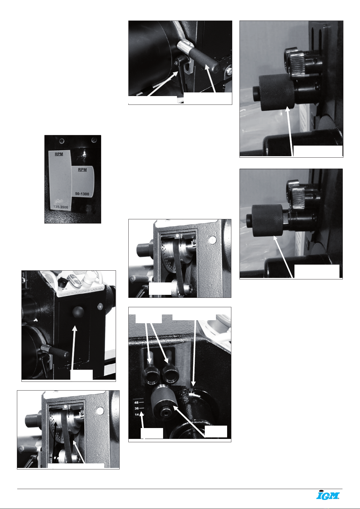
Location of warning signs
Pic. 14
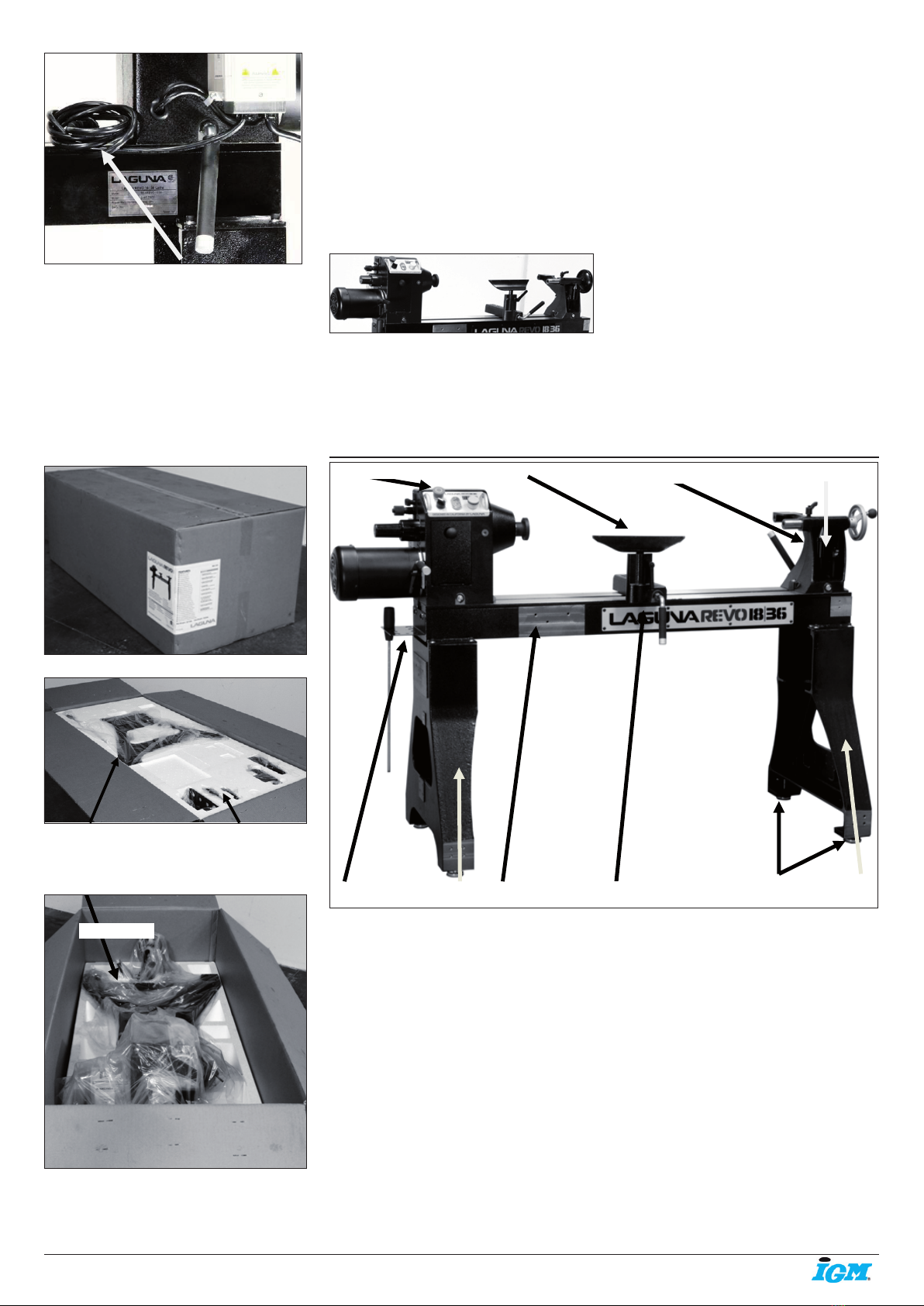
Locking the lathe
It is strongly recommended that the lathe is
never be left unattended in the unlocked
condition.
To lock the machine it is recommended that a
cover (not supplied) is made to lock the control
panel. We have supplied two concepts for
locking the panel (see below). The cover can
be made from wood or plastic.
First, push down the emergency stop. Then
lock the cover together by putting padlocks [not
included] on the two handles on the control
panel. To safeguard your machine from
unauthorized operation and accidental starting
by young children, the use of padlocks is
strongly recommended.
Pic. 15
Pic. 16
4.2 Electrical connections
Make sure that the power supply meets
the machine‘s requirements (230V). We
recommend using a 16 A breaker, tripping
characteristic C (16/1/C). Note.: Perform
adjustments with the help of a qualied
electrician.
VFD with cover open
Pic. 17
Wooden safety cover Padlocks
Padlocks
Emergency stop switch
Plastic safety cover