tornos DECO 7e User manual

TORNOS SA
CH−2740 MOUTIER
http://www.tornos.ch
INSTALLATION
Printed in Switzerland Copyright E1999−2007
ΔATTENTION !
Before handling / operating the machine,
read first the SAFETY REGULATIONS !
DECO 7e / 10e
199222 − 0017
199224 − 0017
300440 en


INSTALLATION − DECO 7e / 10e − 0017
300440 en − 01/07 3
TABLE OF CONTENTS
1. GENERALITIES 1. . . . . . . . . . . . . . . . . . . . . . . . . . . . . . . . . . . . . . . . . . . . . . . . . . . . . . . .
1.1 GENERAL INFORMATION 1. . . . . . . . . . . . . . . . . . . . . . . . . . . . . . . . . . . . . . . . . . . . . . . . . . . . . . . . . . .
1.1.1 Conformity to standards and directives 1. . . . . . . . . . . . . . . . . . . . . . . . . . . . . . . . . . . . . . . . . . . . . . . . .
1.2 ADDRESSES 1. . . . . . . . . . . . . . . . . . . . . . . . . . . . . . . . . . . . . . . . . . . . . . . . . . . . . . . . . . . . . . . . . . . . . . .
1.3 DIFFERENTIATION OF DEGREES OF RISK 2. . . . . . . . . . . . . . . . . . . . . . . . . . . . . . . . . . . . . . . . . . .
1.4 IMPORTANT SAFETY INDICATIONS 2. . . . . . . . . . . . . . . . . . . . . . . . . . . . . . . . . . . . . . . . . . . . . . . . . .
2. GENERAL 1. . . . . . . . . . . . . . . . . . . . . . . . . . . . . . . . . . . . . . . . . . . . . . . . . . . . . . . . . . . . .
2.1 SAFETY MEASURES & DEVICES 1. . . . . . . . . . . . . . . . . . . . . . . . . . . . . . . . . . . . . . . . . . . . . . . . . . . .
2.2 STANDARD MACHINE DATA 1. . . . . . . . . . . . . . . . . . . . . . . . . . . . . . . . . . . . . . . . . . . . . . . . . . . . . . . . .
3. UNPACKING − CLEANING 1. . . . . . . . . . . . . . . . . . . . . . . . . . . . . . . . . . . . . . . . . . . . . .
3.1 UNPACKING 1. . . . . . . . . . . . . . . . . . . . . . . . . . . . . . . . . . . . . . . . . . . . . . . . . . . . . . . . . . . . . . . . . . . . . . .
3.2 CLEANING THE MACHINE 1. . . . . . . . . . . . . . . . . . . . . . . . . . . . . . . . . . . . . . . . . . . . . . . . . . . . . . . . . .
4. LOCATION AND INSTALLATION 1. . . . . . . . . . . . . . . . . . . . . . . . . . . . . . . . . . . . . . . .
4.1 FLOOR PLANS 1. . . . . . . . . . . . . . . . . . . . . . . . . . . . . . . . . . . . . . . . . . . . . . . . . . . . . . . . . . . . . . . . . . . . .
4.1.1 Floor Space of DECO 10e 1. . . . . . . . . . . . . . . . . . . . . . . . . . . . . . . . . . . . . . . . . . . . . . . . . . . . . . . . . . .
4.1.2 Floor Space with ROBOBAR SSF−107 2. . . . . . . . . . . . . . . . . . . . . . . . . . . . . . . . . . . . . . . . . . . . . . . .
4.1.3 Floor Space with ROBOBAR SBF−216 3. . . . . . . . . . . . . . . . . . . . . . . . . . . . . . . . . . . . . . . . . . . . . . . .
4.1.4 Floor Space with Tryton 4. . . . . . . . . . . . . . . . . . . . . . . . . . . . . . . . . . . . . . . . . . . . . . . . . . . . . . . . . . . . . .
4.2 FLOOR LOCATION 5. . . . . . . . . . . . . . . . . . . . . . . . . . . . . . . . . . . . . . . . . . . . . . . . . . . . . . . . . . . . . . . . .
4.2.1 Floor Preparation 5. . . . . . . . . . . . . . . . . . . . . . . . . . . . . . . . . . . . . . . . . . . . . . . . . . . . . . . . . . . . . . . . . . .

INSTALLATION − DECO 7e / 10e − 0017
300440 en − 01/07 4
4.3 PACKING AND HANDLING FOR REMOVALS 5. . . . . . . . . . . . . . . . . . . . . . . . . . . . . . . . . . . . . . . . . .
4.4 ELECTRIC INSTALLATION 7. . . . . . . . . . . . . . . . . . . . . . . . . . . . . . . . . . . . . . . . . . . . . . . . . . . . . . . . . .
4.4.1 Installation Characteristics 8. . . . . . . . . . . . . . . . . . . . . . . . . . . . . . . . . . . . . . . . . . . . . . . . . . . . . . . . . . .
4.5 ELECTRIC CONNECTION DECO 10E 9. . . . . . . . . . . . . . . . . . . . . . . . . . . . . . . . . . . . . . . . . . . . . . . .
4.5.1 Connecting TORNOS Autotransformer 10. . . . . . . . . . . . . . . . . . . . . . . . . . . . . . . . . . . . . . . . . . . . . . . . .
4.5.2 Connecting Non-TORNOS Autotransformer 11. . . . . . . . . . . . . . . . . . . . . . . . . . . . . . . . . . . . . . . . . . . .
4.6 CONNECTING BARFEEDER AND CHIP CONVEYOR 12. . . . . . . . . . . . . . . . . . . . . . . . . . . . . . . . . .
4.7 PNEUMATICS INSTALLATION 13. . . . . . . . . . . . . . . . . . . . . . . . . . . . . . . . . . . . . . . . . . . . . . . . . . . . . . .
4.7.1 Air Quality Specification 13. . . . . . . . . . . . . . . . . . . . . . . . . . . . . . . . . . . . . . . . . . . . . . . . . . . . . . . . . . . . . .

INSTALLATION − DECO 7e / 10e − 0017
300440 en − 01/07 Chap. 1.2 /1
1. GENERALITIES
1.1 GENERAL INFORMATION
This document is written based on the information available at the moment
of its publication.
TORNOS S.A. may not be held responsible, however, in case of errors or
omissions.
The original language of this document is French.
The information contained in this document is the property of TORNOS S.A.,
which is intended exclusively for internal customer usage, and may not be dis-
closed to or reproduced for third parties.
1.1.1 Conformity to standards and directives
The CE-marking i indicates that this product conforms with the
European standards of safety, health, environment and protection.
1.2 ADDRESSES
TORNOS S.A.
Rue Industrielle 1 1 1
CH−2740 MOUTIER / SUISSE
Tél. 032 / 494 44 44
Fax 032 / 494 49 03
TORNOS TECHNOLOGIES
IBERICA
Pol. Ind. El Congost
Avda. St Julia, 206 Nave 8
E−08400 GRANOLLERS
Tel. (34) 93 846 59 43
Fax (34) 93 849 66 00
TORNOS−TECHNOLOGIES
DEUTSCHLAND
Karlsruher Str. 38
D−75179 PFORZHEIM
Tel. 07231/ 910 70
Fax 07231/ 910 750
TORNOS TECHNOLOGIES
ITALIA SRL Via Einstein, 24
I−20090 ASSAGO / MI
Tel. 02 45 77 17 01
Fax 02 45 70 16 48
TORNOS TECHNOLOGIES
FRANCE
Boîte postale 330
ST−PIERRE EN FAUCIGNY
F74807 LA ROCHE
S / FORON CEDEX
Tél. 04 50 038 333
Fax 04 50 038 907
TORNOS TECHNOLOGIES
US CORPORATION
70 Pocono Road PO. Box 325
BROOKFIELD CT 06804 / USA
Tel. (203) 775−4319
Fax (203) 775−4281
TORNOS TECHNOLOGIES UK Ltd
Tornos House
Whitwick Business Park Coalville
Leicestershire
LE67 4JQ
Tel. 01530 513100
Fax 01 530 814212
TORNOS SHANGHAI
REPRESENTATIVE OFFICE
Tower B, Office 512−513
Far East International Plaza
No. 319 Xianxia Road
CN−SHANGHAI 200335
Tel. +86 21−62351235
Fax +86 21−62351938

INSTALLATION − DECO 7e / 10e − 0017
300440 en − 01/07 Chap. 1.4 /2
1.3 DIFFERENTIATION OF DEGREES OF RISK
These instructions indicate a number of safety measure symbols which
appear also on the machine and are intended to protect the user, his/her
effects and the environment from injuries and damage as applicable.
Below, you will find the safety symbols, their headings and definitions. Please,
read these first before you continue.
ΔDanger !
indicates a direct danger of death or serious injury.
ΔWarning !
indicates an object or action which may cause death or serious
injury.
ΔCaution !
indicates an object or action which may cause injury or serious
damage.
.Attention !
indicates incorrect actions or such that may cause damage.
⊗Prohibition !
indicates an action or operation prohibited because of evident or
alleged hazards.
⇒Info :
Gives information or comment related to safety.
Note :
Gives information unrelated to safety
1.4 IMPORTANT SAFETY INDICATIONS
ΔWarning !
Read the instruction before operating the machine.
Should the user disregard the instructions of this manual, TORNOS SA
declines any liability whatsoever.
.Attention !
Certain maintenance works are absolutely necessary to ensure good
operation of the machine. They are given in the MAINTENANCE
SCHEDULE on the machine
(or see Instructions: OPERATION-MAINTENANCE).
.Attention !
TORNOS SA disclaims all responsibility for any modifications carried
out by the customer to the machine, and to its related equipment and
software, without agreement ratified by TORNOS SA.

INSTALLATION − DECO 7e / 10e − 0017
300440 en − 01/07 Chap. 2.2 /1
2. GENERAL
2.1 SAFETY MEASURES & DEVICES
These are described in the Instructions 300480: SAFETY REGULATIONS
DECO 2000.
ΔWarning !
Failure to comply with the safety regulations may
cause serious accidents.
2.2 STANDARD MACHINE DATA
Feature Note Data
Length : 1550 mm
Width : 1000 mm
Height : 1800 mm
Weight : enclosure approx. 670 kg
DECO 0017 approx. 1500 kg
Specific load : DECO 0017
(per surface unit) 4.2 daN/cm2
⇒Note :
For more details, consult your operating instructions entitled :
OPERATION & MAINTENANCE.
⇒Note :
For more details, consult your operating instructions entitled :
MACHINE EQUIPMENT.

INSTALLATION − DECO 7e / 10e − 0017
300440 en − 01/07 Chap. 2.2 /2
>>>

INSTALLATION − DECO 7e / 10e − 0017
300440 en − 01/07 Chap. 3.2 /1
3. UNPACKING − CLEANING
3.1 UNPACKING
Note :
Proceed according to the TRANSPORT INFO sheet 300360 included in
the machine’s documentation.
− Pull out nails from the cover and then from the walls of the case.
− Remove the vacuum-packing plastic.
− Remove the wooden wedges and ropes that hold various items.
3.2 CLEANING THE MACHINE
− Wash carefully with gasoline or petroleum-soaked cloth all rust-protected
surfaces without damaging or disrupting anything.
− Wash on well ventilated premises.
− Avoid using compressed air and substances that could damage plastic
materials.
>>>

INSTALLATION − DECO 7e / 10e − 0017
300440 en − 01/07 Chap. 3.2 /2
>>>
INSTALLATION − DECO 7e / 10e − 0017
300440 en − 01/07 Chap. 4.1.1 /1
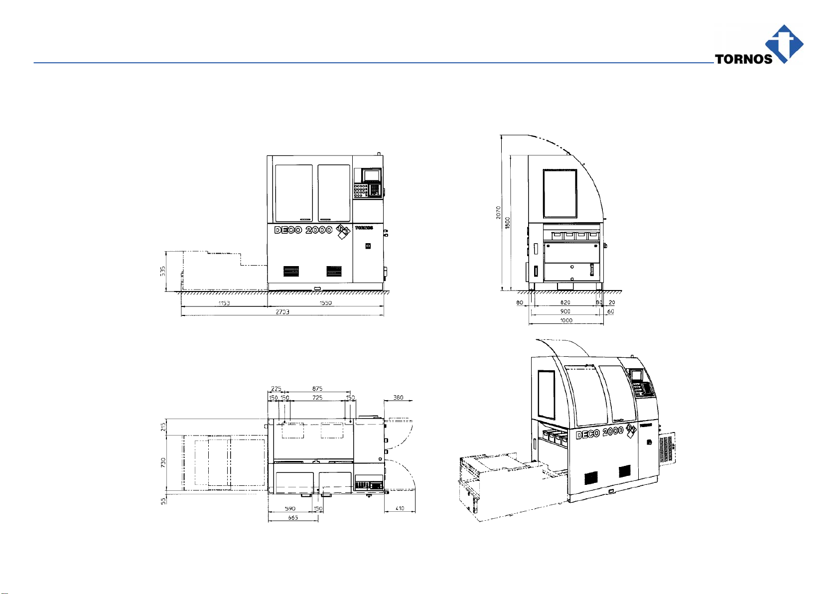
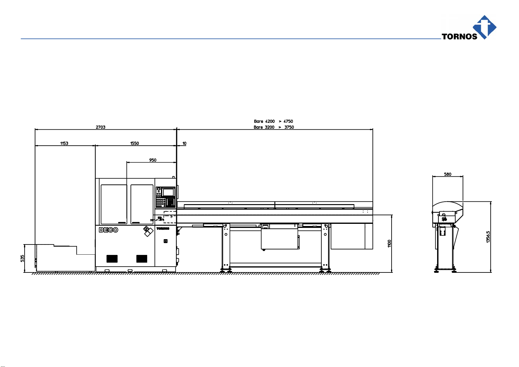
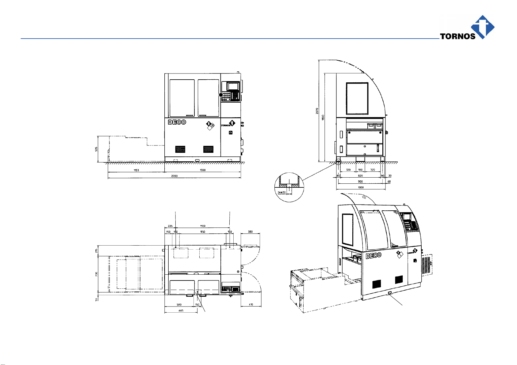
4. LOCATION AND INSTALLATION
4.1 FLOOR PLANS
4.1.1 Floor Space of DECO 10e

INSTALLATION − DECO 7e / 10e − 0017
300440 en − 01/07 Chap. 4.1.2 /2
4.1.2 Floor Space with ROBOBAR SSF−107
INSTALLATION − DECO 7e / 10e − 0017
300440 en − 01/07 Chap. 4.1.3 /3
4.1.3 Floor Space with ROBOBAR SBF−216

INSTALLATION − DECO 7e / 10e − 0017
300440 en − 01/07 Chap. 4.1.4 /4
4.1.4 Floor Space with Tryton
305166f1

INSTALLATION − DECO 7e / 10e − 0017
300440 en − 01/07 Chap. 4.3 /5
4.2 FLOOR LOCATION
See Fig. 300.
− Do not level the machine (the floor to be level) :
It rests on three Support Plates D, two in the back and one in the front of
the machine.
− Anchor the machine in the floor with three screws by running them through
the holes in three Support Plates D.
The screws merely fix the machine to the floor and cannot support its
weight.
− Arrange a barfeeder according to its manufacturer’s recommendations.
− Take into account the dimensions of various options that you can attach to
the machine (bar feed tube, barfeeder, conveyor, etc.) because the floor
plan shows the basic machine equipment only.
4.2.1 Floor Preparation
See Fig. 300 and TRANSPORT INFO Sheet 300360.
The machine rests on three support plates.
The floor at these 3 points must be hard, stable, vibration-free and perfectly
level.
4.3 PACKING AND HANDLING FOR REMOVALS
When you move the machine within between your premises, follow the follow-
ing packing and handling requirements :
Note :
See TRANSPORT INFO Sheet 300360 and its Figures 1 to 3 in particu-
lar.
Packing and handling :
IN CASES (seaworthy packing)
− Run cords or chains through as marked.
ON PALLETS (under plastic)
− Pass packing needles of approx. 80 x 80 mm through Rectangular Pass-
ages B.
− Proceed with nailing on the road truck deck.
WITH FORK LIFT TRUCK or LOW LIFT TRUCK
− Pass the fork through Rectangular Passages A.
Fork length min.: 1100 mm
Note :
Before removing the lathe, clean it according to Para: PERIODICAL
CLEANING in your OPERATION & MAINTENANCE instructions.
INSTALLATION − DECO 7e / 10e − 0017
300440 en − 01/07 Chap. 4.3 /6
D
D
DD
300
FLOOR LOCATION
INSTALLATION − DECO 7e / 10e − 0017
300440 en − 01/07 Chap. 4.4 /7
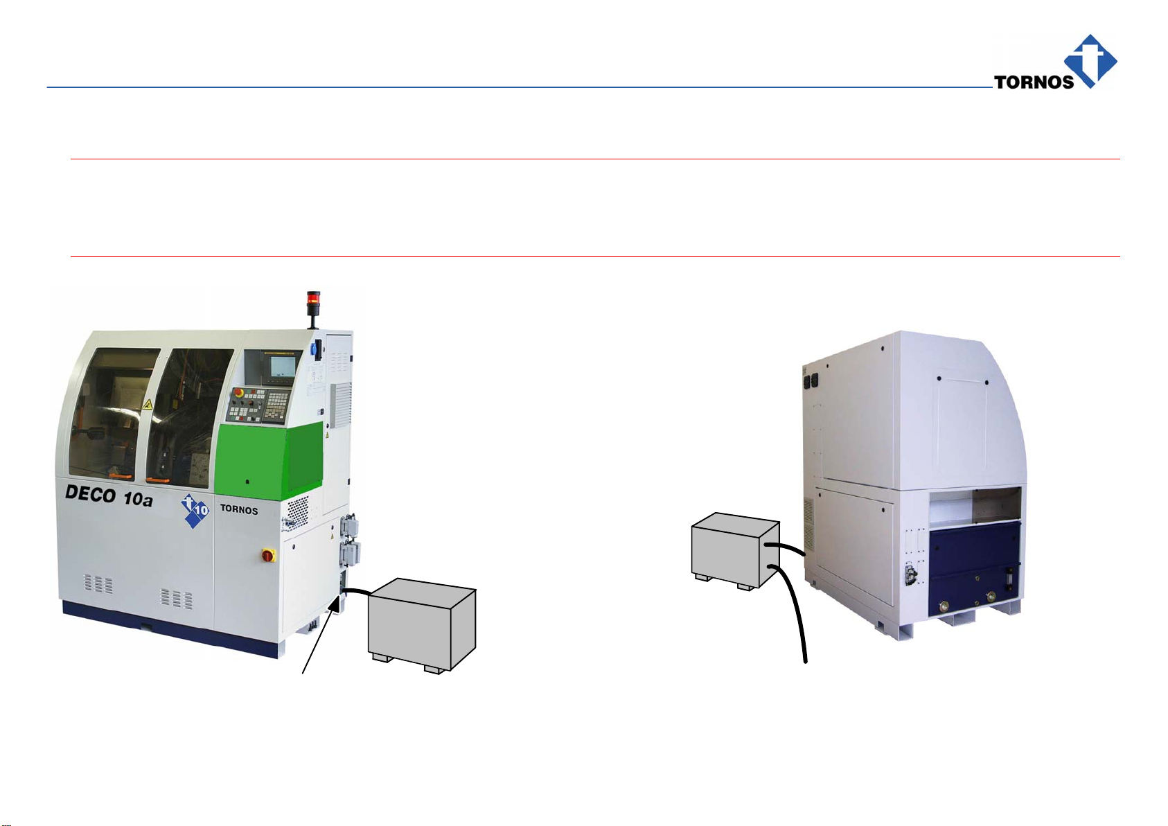
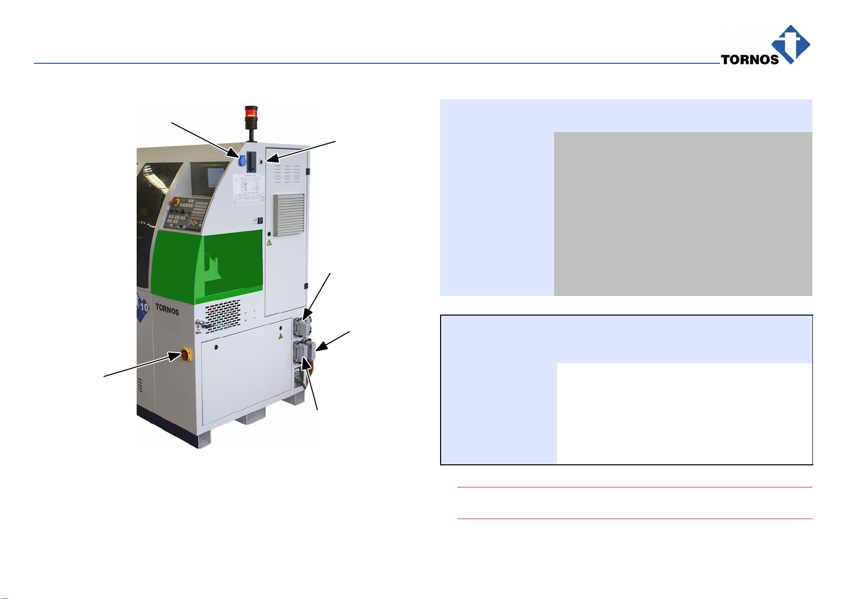
4.4 ELECTRIC INSTALLATION
ΔDanger !
For connecting and any other work on the electric equipment, the power must be cut off. The work must be carried out only by an authorized technician to
avoid the danger of electrocution.
Deficient connections may also cause serious damage to the installation.
301Autotransformer
Machine input terminal box to the mains
Autotransformer
INSTALLATION − DECO 7e / 10e − 0017
300440 en − 01/07 Chap. 4.4.1 /8
Version 0017
XS94
XS60
(2)
QS0
XS42
XS1
106
LOCATION OF ELEMENTS
Ref. Description
QS0 Main Switch
XS60 Fire protection system
XS94 Barfeeder socket, fixed
XS94 Barfeeder socket, fixed
XS42 Interface socket for pump, cooling.
(1) Reserve
(2) Socket for eternet
TM1 Autotransformer (if required)
TC1 Mains voltage transformer inside lathe’s enclosure
XS1 Single phase current socket 230V 50Hz
4.4.1 Installation Characteristics
Feature Notes Data
Lathe power: Average effective power:
(acc. to lathe application) 5 kW approx.
Installed power: 8 kVA approx.
Mains tolerances: rated voltage:
frequency: +/−10%
+/−1 Hz for 50/60 Hz
Main circuit-breaker: at machine input 25 A
ΔSee also your instructions: SAFETY REGULATIONS DECO 7a / 10a

INSTALLATION − DECO 7e / 10e − 0017
300440 en − 01/07 Chap. 4.5 /9
4.5 ELECTRIC CONNECTION DECO 10e
Cut off mains supply
no see chapter
Connecting
TORNOS
autotransformer
Connect mains supply
to machine. Section acc. to ASE 4 mm2or acc.
to local regulations.
Mains Machine
terminal box
see fig. 106
L1
L2
L3
L1
L2
L3
Turn on Main Switch QS0
Check XS1 service socket
voltage.
yes
see fig.106
220V−240V
or US socket voltage
100V−110V ?
Machine properly connected
yes
Mains 400V/50Hz
or 460V/60Hz?

INSTALLATION − DECO 7e / 10e − 0017
300440 en − 01/07 Chap. 4.5.1 /10
4.5.1 Connecting TORNOS Autotransformer
1
Connect 60 Hz mains supply.
.Caution !
The autotransformer is located
outside the machine.
no
Autotransformer
TORNOS Connecting Non-TORNOS
autotransformer, see para. below
Machine input
terminal box
L1
L2
L3
yes
Cut off mains supply.
50Hz ?
Mains
input
50 Hz
230V
230V
230V 400V
400V
500V 400V
500V
500V
200V
200V
200V Machine input
terminal box
see fig. 106
L1
L2
L3
Mains
input
60 Hz
230V
230V
230V 460V
460V
500V 460V
500V
500V
200V
200V
200V
yes no
2
Connect 50 Hz mains supply.
This manual suits for next models
3
Table of contents
Other tornos Lathe manuals


Popular Lathe manuals by other brands

EINHELL
EINHELL BT-ML 300 operating instructions

Wen
Wen LA8800 manual

Scheppach
Scheppach DM1100T Translation of the original instruction manual

Promac
Promac PBD-2870 manual

Central Machinery
Central Machinery 03173 Assembly and operating instructions

Teknatool
Teknatool NOVA Comet II Instructions and parts manual


