Laird Sentrius BT610 User manual

A
™
Version 0.1

https://www.lairdconnect.com/iot-devices/iot-
sensors/sentrius-bt610-io-sensor
2
© Copyright 2021 Laird Connectivity
All Rights Reserved
Americas: +1-800-492-2320
Europe: +44-1628-858-940
Hong Kong: +852 2923 0610
Version
Date
Notes
Contributor
Approver
0.1
22 April 2021
Preliminary Release
Brent Mikkelsen
Dave Neperud
Rich Walters
Robert Gosewehr
Greg Leach
Chris Boorman

https://www.lairdconnect.com/iot-devices/iot-
sensors/sentrius-bt610-io-sensor
3
© Copyright 2021 Laird Connectivity
All Rights Reserved
Americas: +1-800-492-2320
Europe: +44-1628-858-940
Hong Kong: +852 2923 0610
1About this Guide...........................................................................................................................................................5
2Introduction..................................................................................................................................................................5
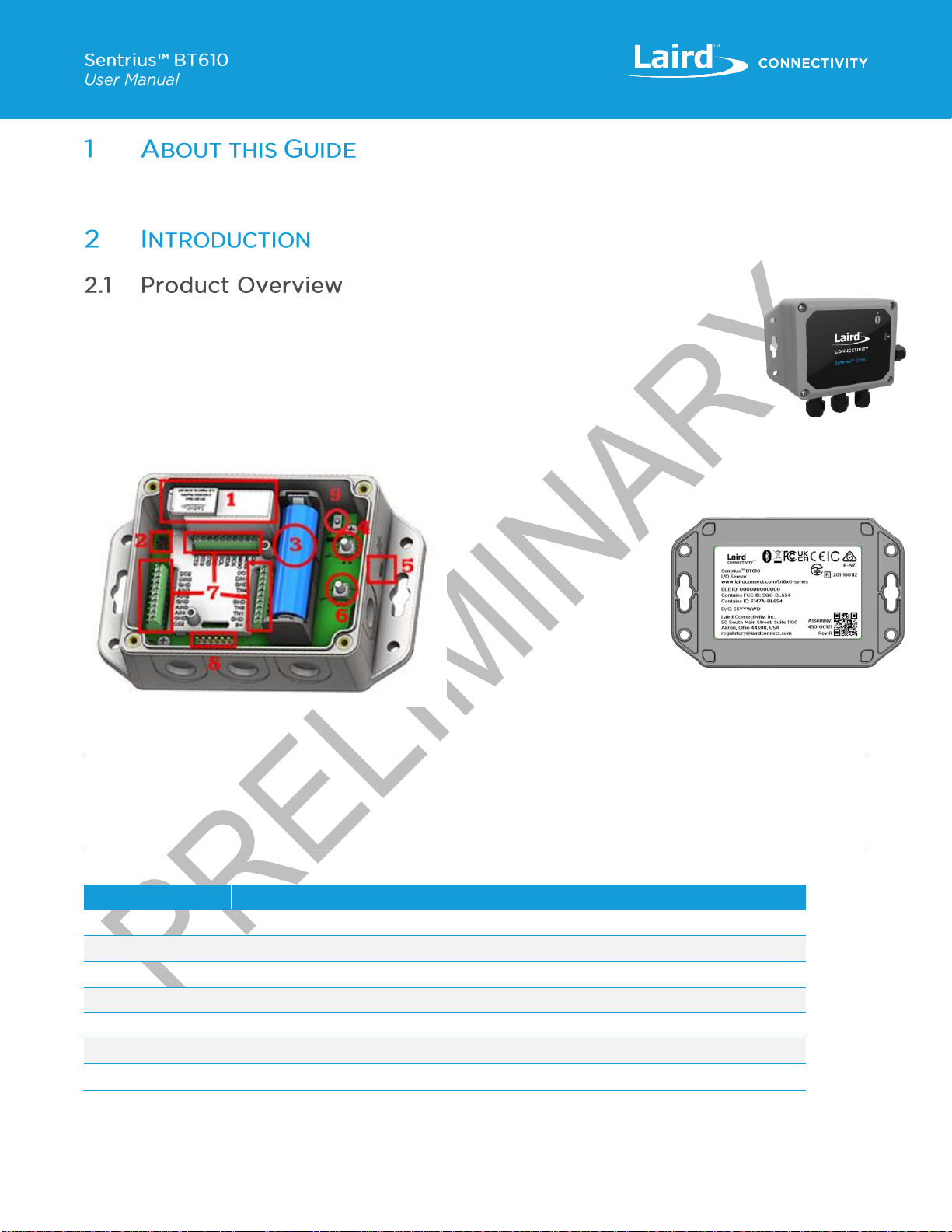
2.1 Product Overview................................................................................................................................................5
2.2 Specifications......................................................................................................................................................6
3Device Operation.........................................................................................................................................................6
3.1 Activating the BT610 ...........................................................................................................................................6
3.2 Bluetooth Connection..........................................................................................................................................6
3.3 Battery Check......................................................................................................................................................6
3.4 Factory Reset......................................................................................................................................................6
3.5 Reset Button.......................................................................................................................................................6
3.6 Replacing Batteries .............................................................................................................................................6
3.7 Care and Maintenance ........................................................................................................................................7
4Sensor Architecture......................................................................................................................................................7
4.1 Advertisements ...................................................................................................................................................7
4.1.1 1M PHY.........................................................................................................................................................7
4.1.2 1M PHY Scan Response................................................................................................................................8
4.1.3 LE Coded PHY..............................................................................................................................................9
4.1.4 Record Event Types ....................................................................................................................................11
4.1.5 Tamper State...............................................................................................................................................11
4.1.6 Flags...........................................................................................................................................................12
4.1.7 Alarm Map...................................................................................................................................................12
4.1.8 Digital Alarm Map ........................................................................................................................................13
4.1.9 Reset Reason..............................................................................................................................................13
4.2 CBOR...............................................................................................................................................................13
4.2.1 Methods......................................................................................................................................................14
4.3 Sensor Configuration.........................................................................................................................................15
4.3.1 Example......................................................................................................................................................15
4.4 Event Log..........................................................................................................................................................15
5Mobile Application......................................................................................................................................................16
5.1 Overview...........................................................................................................................................................16
5.2 Using the Sentrius™ BT610 Sensor Mobile App on Device.................................................................................16
5.3 Application Navigation.......................................................................................................................................20
5.3.1 Sensor Type................................................................................................................................................20
5.3.2 Device Settings............................................................................................................................................29
5.3.3 Bluetooth Settings........................................................................................................................................30
5.3.4 Logging.......................................................................................................................................................32
5.3.5 Permissions.................................................................................................................................................33

https://www.lairdconnect.com/iot-devices/iot-
sensors/sentrius-bt610-io-sensor
4
© Copyright 2021 Laird Connectivity
All Rights Reserved
Americas: +1-800-492-2320
Europe: +44-1628-858-940
Hong Kong: +852 2923 0610
6Bluetooth SIG.............................................................................................................................................................34
7FCC and ISED Canada Regulatory Statements...........................................................................................................34
8ISED Canada Regulatory Statements.........................................................................................................................34
9CE Regulatory - PENDING.........................................................................................................................................36
9.1 EU Declarations of Conformity...........................................................................................................................36
10 Japan (MIC) Regulatory..............................................................................................................................................36
11 ACMA (Australia/NZ) Certification...............................................................................................................................36
12 Ordering Information ..................................................................................................................................................37
13 Label Info...................................................................................................................................................................37
14 Additional Assistance .................................................................................................................................................38
15 Definitions and Abbreviations......................................................................................................................................39
16 References................................................................................................................................................................40

https://www.lairdconnect.com/iot-devices/iot-
sensors/sentrius-bt610-io-sensor
5
© Copyright 2021 Laird Connectivity
All Rights Reserved
Americas: +1-800-492-2320
Europe: +44-1628-858-940
Hong Kong: +852 2923 0610
This document provides a comprehensive guide on how to configure the Sentrius™BT610 Sensor, including Bluetooth settings
and for all connected I/O.
The Sentrius™BT610 Sensor is a battery powered, Bluetooth v5 long-range integrated sensor platform
enabling robust, reliable sensor data transfer in the harshest of environments. It contains multiple sensor
interface options for ultimate design choice. The device has options for four analog inputs, two digital
inputs, two digital outputs, four thermistors, three AC current sensors, one ultrasonic sensor, one pressure
sensor, one SPI, one I2C, and one UART.
Not all these options can be configured at one time, refer to Table 1. The BT610 is powered by Laird
Connectivity’s field proven BL654 [A] BLE module that integrates Nordic Semiconductor’s nRF52840 SoC
silicon [B].
Figure 1: Inside of the Sentrius™BT610 sensor
1. FlexPIFA Antenna
2. SWD Programming
Header
3. Lithium Battery
4. Reset Button
5. Magnetic Switch
6. Pairing/Boot Button
7. Terminal Blocks for
Wire Inputs
8. FTDI USB Header
9. Tamper Switch
Figure 2: Back of the Sentrius™
BT610 sensor
Note: Laird Connectivity has a comprehensive staff of design services engineers available to help customize the sensor.
Please contact your local Laird Connectivity sales representative for more details.
Note: FTDI USB connectivity must be via a 3.3V I/O voltages type adapter [C].
Table 1: BT610 Configuration Options
Mode
Description
Not Configured
All I/O disabled
Analog
Up to 4 Current or Voltage inputs
Digital
Up to 2 Digital Inputs, up to 2 Digital Outputs
Temperature
Up to 4 NTC Thermistors
Current
Up to 3 AC Current sensors
Ultrasonic/Pressure
Ultrasonic or Pressure sensor input
SPI/I2C
Up to 2 SPI slave devices, up to 1 I2C bus, up to 1 Serial Port

https://www.lairdconnect.com/iot-devices/iot-
sensors/sentrius-bt610-io-sensor
6
© Copyright 2021 Laird Connectivity
All Rights Reserved
Americas: +1-800-492-2320
Europe: +44-1628-858-940
Hong Kong: +852 2923 0610
See the BT610 product brief for detailed specifications. Available from the documentation tab of the BT610 series product page:
https://www.lairdconnect.com/sentrius-bt610-io-sensor
The Sentrius™ BT610 does not have a power switch. It is shipped with an installed battery and is in a low power state called
shelf mode.
To wake the device, option one is to open the BT610 press and hold the pairing/boot button, item 6 as indicated in Figure 1, for
at least three seconds until the green LED turns on. Option two is to hold a magnet near the magnet switch touch point, item 5
as indicated in Figure 1, for three seconds. Either of these will put the device in active mode and the green LED blinks once a
second. The BT610 is now ready for normal operation / configuration. This can be done using a mobile app or a supporting
gateway. The LED blinks for 30 seconds or until a connection is made or the button is pressed again.
Once in active mode the BT610 will be able to report back sensor readings for all connected inputs such as ADC, ultrasonic,
pressure, and thermistors.
When a connection is established using a mobile app or a supporting gateway there is a passkey that needs to be entered to
complete the connection. The default passkey for the BT610 is the number 123456. This passkey should be changed at the
earliest convenience to help protect the device from unauthorized users. Changing the passkey can be done through the mobile
app and will be found in more detail later in the document in the mobile application section.
Quickly press the pairing/boot button, item 6 as indicated in Figure 1,to perform a battery check. If the battery is good, the
sensor briefly turns on the yellow LED for one second. If the battery is below the recommended operating voltage, then the LED
does not blink but the sensor will still try to advertise. It is possible for the mobile application to connect to the BT610 but take
note this may drain the battery even faster.
When the pairing/boot button, item 6 as indicated in Figure 1, is held for greater than ten and less than twenty seconds, the
factoryresetprocessis initiated.Whenthe button isreleasedtheLEDwill turn yellowor redto indicateif thereset was successful.
If the LED turns red then a factory reset is not allowed using the button, this is because the factory reset parameter is set as
disabled, as described below Device Settings. If the LED turns yellow then a factory reset is allowed, meaning the factory reset
parameter is enabled. Once the yellow LED turns off the BT610 has been reset to factory settings. The BT610 will need to be
put back into active mode by holding the pairing/boot button for three seconds.
A factory reset erases all logs, pairing information, and resets the configuration to its default state. It will take the BT610 five
seconds after the reset before it is running again, and a button press can be detected.
Do not confuse this with the factory reset operation. This button, item 4 as indicated in Figure 1, is only used for performing a
reset of the BL654 micro. After the reset occurs all the configuration data is still intact, and the device will begin running in the
mode it was enabled before the reset button was pressed.
The battery is a ER14505 Lithium Thionyl Chloride type (3.6v).

https://www.lairdconnect.com/iot-devices/iot-
sensors/sentrius-bt610-io-sensor
7
© Copyright 2021 Laird Connectivity
All Rights Reserved
Americas: +1-800-492-2320
Europe: +44-1628-858-940
Hong Kong: +852 2923 0610
While the BT610 is IP67 rated, that rating applies when the lid, plugs &/or cable glands are all correctly assembled, so we only
recommend placing the BT610 in wet / dusty harsh environments (aligned with the IP67 rating) after complete / careful
assembly. Refer to the Hardware Configuration and Installation Guide available on the BT610 product page for more detail.
The BT610 does not require any user calibration.
The BT610 can be cleaned with a mild, non-abrasive detergent.
The Sentrius™ BT610 advertises events. An event can be a temperature measurement, an alarm, a battery measurement, a
button press, or digital input activating. The configuration of a sensor determines what kind of events it generates.
You can configure the sensor using a Bluetooth connection to the mobile app provided or using the shell interface [E] .
The protocol used is defined in detail in [E].
Advertising each event once it becomes active is the default behavior of the sensor. This provides ample time for a gateway to
detect an event, maximizes thelifetime ofthe battery, and allows the sensorto bea good RFcitizen. Once a sensor is configured,
it is possible that a gateway never needs to connect to a sensor. If multiple events occur at the same time, the sensor queues
events and advertises each one for the configured advertising duration (default of 15 seconds).
If the sensor is configured to advertise indefinitely, then the advertisement queue is bypassed.
For each new event, the record number increments. You can use this value to filter out duplicate advertisements.
The TLV (type-length-value) fields are shown in the order that is broadcast by the sensor. However, this order is not guaranteed.
The sensor can be configured to transmit with an output power of +8 dBm. It can also be configured to use the LE coded PHY.
When using the coded PHY, the scan response isn’t used.
Table 2: 1M PHY
Byte
Description
Value/Notes
10
0x02
Length (0x02)
1
GAP_ADTYPE_FLAGS
Type (0x01)
2
GAP_ADTYPE_FLAGS_BREDR_NOT_SUPPORTED
Data
3
0x1b (27)
Length (length is not included in overall length)
4
GAP_ADTYPE_MANUFACTURER_SPECIFIC
0xFF (Type)
5
Company ID 1
0x77 (Laird)
6
Company ID 2
0x00
7
Protocol ID LSB
0x01 (Identifies the advertisement format)
8
Protocol ID MSB
0x00
9
Network ID LSB
Assigned during configuration. Default is 0x000.
10
Network ID MSB
This can be used for filtering advertisements
11
Flags LSB
Indicate the current state of the system
12
Flags MSB
See: 4.1.6 Flags
13
BD_ADDR 0
Random static Bluetooth address (0 is LSB)

https://www.lairdconnect.com/iot-devices/iot-
sensors/sentrius-bt610-io-sensor
8
© Copyright 2021 Laird Connectivity
All Rights Reserved
Americas: +1-800-492-2320
Europe: +44-1628-858-940
Hong Kong: +852 2923 0610
Byte
Description
Value/Notes
14
BD_ADDR 1
15
BD_ADDR 2
16
BD_ADDR 3
17
BD_ADDR 4
18
BD_ADDR 5
MSB
19
Record Type
See: 4.1.4 Record Event Types
20
Record Number LSB
This count matches the index in the NV log. It will
rollover
21
Record Number MSB
22
Epoch 0 LSB
This is a timestamp in seconds from Jan 1, 1970
23
Epoch 1
24
Epoch 2
25
Epoch 3 MSB
26
Data byte 0 LSB
See: table 4 to match record type to data
27
Data byte 1
28
Data byte 2
29
Data byte 3 (MSB)
30
Reset Count LSB
For testing purposes.
Table 3: 1M PHY scan response
Byte
Description
Value/Notes
0
0x10 (16)
Length (length is not included in overall length)
1
GAP_ADTYPE_MANUFACTURER_SPECIFIC
0xFF (Type)
2
Company ID 1
0xE4 (Laird)
3
Company ID 2
0x00
4
Protocol ID LSB
0x03 (Identifies the advertisement format)
5
Protocol ID MSB
0x00
6
Product ID LSB
Identification of the device transmitting
7
Product ID MSB
8
Firmware Version Major
Version of the main application installed
9
Firmware Version Minor
10
Firmware Version Patch
11
Firmware Type
Firmware type can be used to interleave versions for
multiple devices
12
Configuration Version
Configuration version is updated when advertisement
is built
13
Boot Loader Version Major

https://www.lairdconnect.com/iot-devices/iot-
sensors/sentrius-bt610-io-sensor
9
© Copyright 2021 Laird Connectivity
All Rights Reserved
Americas: +1-800-492-2320
Europe: +44-1628-858-940
Hong Kong: +852 2923 0610
Byte
Description
Value/Notes
14
Boot Loader Version Minor
15
Boot Loader Version Patch
16
Hardware Version
17
Length (X)
(<=13)
18
DEVICE_NAME
0x08 or 0x09
19
Max Complete Name (0x09) is 12 characters
20
21
22
23
24
25
26
27
28
29
30
Table 4: LE Coded PHY
Byte
Description
Value/Notes
0
0x02
Length (0x02)
1
GAP_ADTYPE_FLAGS
Type (0x01)
2
GAP_ADTYPE_FLAGS_BREDR_NOT_SUPPORTED
Data
3
0x26 (38)
Length (length is not included in overall length)
4
GAP_ADTYPE_MANUFACTURER_SPECIFIC
0xFF (Type)
5
Company ID 1
0x77 (Laird)
6
Company ID 2
0x00
7
Protocol ID LSB
0x02 (Identifies the advertisement format)
8
Protocol ID MSB
0x00
9
Network ID LSB
Assigned during configuration. Default is 0x000.
10
Network ID MSB
This can be used for filtering advertisements
11
Flags LSB
Indicate the current state of the system
12
Flags MSB
See: 4.1.6 Flags
13
BD_ADDR 0
Random static Bluetooth address (0 is LSB)
14
BD_ADDR 1
15
BD_ADDR 2
16
BD_ADDR 3

https://www.lairdconnect.com/iot-devices/iot-
sensors/sentrius-bt610-io-sensor
10
© Copyright 2021 Laird Connectivity
All Rights Reserved
Americas: +1-800-492-2320
Europe: +44-1628-858-940
Hong Kong: +852 2923 0610
Byte
Description
Value/Notes
17
BD_ADDR 4
18
BD_ADDR 5
MSB
19
Record Type
See: 4.1.4 Record Event Types
20
Record Number LSB
This count matches the index in the NV log. It will
rollover
21
Record Number MSB
22
Epoch 0 LSB
This is a timestamp in seconds from Jan 1, 1970
23
Epoch 1
24
Epoch 2
25
Epoch 3 MSB
26
Data 0 LSB
See: table 4 to match record type to data
27
Data 1
28
Data 2
29
Data 3 (MSB)
30
Reset Count LSB
For testing purposes.
31
Product ID LSB
Identification of the device transmitting
32
Product ID MSB
33
Firmware Version Major
Version of the main application installed
34
Firmware Version Minor
35
Firmware Version Patch
36
Firmware Type
Firmware type can be used to interleave versions for
multiple devices
37
Configuration Version
Configuration version is updated when advertisement
is built
38
Boot Loader Version Major
39
Boot Loader Version Minor
40
Boot Loader Version Patch
41
Hardware Version
42
Length (X)
(<=24)
43
DEVICE_NAME
0x09
44
…
66

https://www.lairdconnect.com/iot-devices/iot-
sensors/sentrius-bt610-io-sensor
11
© Copyright 2021 Laird Connectivity
All Rights Reserved
Americas: +1-800-492-2320
Europe: +44-1628-858-940
Hong Kong: +852 2923 0610
Table 5: Record event types
ID
Event
Data
Format
Datatype
0
RESERVED
-
-
-
12
BATTERY GOOD
BATTERY
VOLTAGE
Millivolts
uint32_t
16
BATTERY BAD
BATTERY
VOLTAGE
Millivolts
uint32_t
17
RESET
RESET REASON
See: section 4.1.9 Reset
Reason
uint32_t
18
SENSOR THERMISTOR
TEMPERATURE 1
TEMPERATURE
Hundredths of degree C
float
19
SENSOR THERMISTOR
TEMPERATURE 2
TEMPERATURE
Hundredths of degree C
float
20
SENSOR THERMISTOR
TEMPERATURE 3
TEMPERATURE
Hundredths of degree C
float
21
SENSOR THERMISTOR
TEMPERATURE 4
TEMPERATURE
Hundredths of degree C
float
22
SENSOR ANALOG VOLTAGE 1
VOLTAGE
Millivolts
float
23
SENSOR ANALOG VOLTAGE 2
VOLTAGE
Millivolts
float
24
SENSOR ANALOG VOLTAGE 3
VOLTAGE
Millivolts
float
25
SENSOR ANALOG VOLTAGE 4
VOLTAGE
Millivolts
float
26
SENSOR ANALOG CURRENT 1
AMPERAGE
Milliamps
float
27
SENSOR ANALOG CURRENT 2
AMPERAGE
Milliamps
float
28
SENSOR ANALOG CURRENT 3
AMPERAGE
Milliamps
float
29
SENSOR ANALOG CURRENT 4
AMPERAGE
Milliamps
float
30
SENSOR PRESSURE 1
PRESSURE
PSI
float
31
SENSOR PRESSURE 2
PRESSURE
PSI
float
32
SENSOR ULTRASONIC 1
DISTANCE
Millimetres
float
33
SENSOR TEMPERATURE
ALARM
BIT MAP
See: 4.1.7 Alarm Map
uint32_t
34
SENSOR ANALOG ALARM
BIT MAP
See: 4.1.7 Alarm Map
uint32_t
35
SENSOR DIGITAL INPUT
ALARM
BIT MAP
See: 4.1.8 Digital Alarm Map
uint32_t
36
SENSOR EPOCH
TIME
Epoch time
uint32_t
37
RESET VERSION 2
RESET REASON
See: 4.1.9 Reset Reason
uint32_t
38
SENSOR TAMPER SWITCH
TAMPER STATE
See: 4.1.5 Tamper State
uint32_t
The tamper switch NOT pressed = 1, switch being HELD DOWN = 0.

https://www.lairdconnect.com/iot-devices/iot-
sensors/sentrius-bt610-io-sensor
12
© Copyright 2021 Laird Connectivity
All Rights Reserved
Americas: +1-800-492-2320
Europe: +44-1628-858-940
Hong Kong: +852 2923 0610
The flags are a bitmask of the current state of the sensor.
Table 6: Flags
Bit
Name
0
RTC was set (epoch)
1
Active Mode
2
Any flag was set
3
Low Battery Alarm
4
Temperature 1 alarm (High1 or High2 or Low1 or Low2 or Delta)
5
Temperature 2 alarm
6
Temperature 3 alarm
7
Temperature 4 alarm
8
Analog 1 alarm (High1 or High2 or Low1 or Low2 or Delta)
9
Analog 2 alarm
10
Analog 3 alarm
11
Analog 4 alarm
12
Digital input 1 state
13
Digital input 2 state
14
Magnet State
15
Tamper Switch State
The alarms are bitmask to show current state of the analog and temperature alarms. When the alarm is set to 1 it is active.
Table 7: Flags
Bit
Name
0
TEMP/ANALOG 1 HIGH 1 ALARM
1
TEMP /ANALOG 1 HIGH 2 ALARM
2
TEMP /ANALOG 1 LOW 1 ALARM
3
TEMP /ANALOG 1 LOW 2 ALARM
4
TEMP /ANALOG 1 DELTA ALARM
5
TEMP/ANALOG 2 HIGH 1 ALARM
6
TEMP /ANALOG 2 HIGH 2 ALARM
7
TEMP /ANALOG 2 LOW 1 ALARM
8
TEMP /ANALOG 2 LOW 2 ALARM
9
TEMP /ANALOG 2 DELTA ALARM
10
TEMP/ANALOG 3 HIGH 1 ALARM
11
TEMP /ANALOG 3 HIGH 2 ALARM
12
TEMP /ANALOG 3 LOW 1 ALARM

https://www.lairdconnect.com/iot-devices/iot-
sensors/sentrius-bt610-io-sensor
13
© Copyright 2021 Laird Connectivity
All Rights Reserved
Americas: +1-800-492-2320
Europe: +44-1628-858-940
Hong Kong: +852 2923 0610
Bit
Name
13
TEMP /ANALOG 3 LOW 2 ALARM
14
TEMP /ANALOG 3 DELTA ALARM
15
TEMP/ANALOG 4 HIGH 1 ALARM
16
TEMP /ANALOG 4 HIGH 2 ALARM
17
TEMP /ANALOG 4 LOW 1 ALARM
18
TEMP /ANALOG 4 LOW 2 ALARM
19
TEMP /ANALOG 4 DELTA ALARM
The digital input alarms are bitmask to show current state of the digital alarms for each pin. When the alarm is set to 1 it is
active.
Table 8: Flags
Bit
Name
0
DIGITAL INPUT 1 ALARM
1
DIGITAL INPUT 2 ALARM
The reset reasons come from the RESETREAS register in the Nordic nRF52840. Reserved values do not apply to the sensor.
Table 9: Reset reasons
Value
Reason
0
Power Up
1
Reset Pin
2
Watchdog
3
Software Request
4
CPU Lock-up detected
5
Reserved
6
Low Power Comparator
7
Reserved
8
Reserved
9
Reserved
10
Unknown
Refer to [E] for more details.
The sensor does not support batch commands.
More details can be found at https://cbor.io/spec.html.

https://www.lairdconnect.com/iot-devices/iot-
sensors/sentrius-bt610-io-sensor
14
© Copyright 2021 Laird Connectivity
All Rights Reserved
Americas: +1-800-492-2320
Europe: +44-1628-858-940
Hong Kong: +852 2923 0610
Table 10: CBOR methods
Method
(Command)
Method
Id
Parameters
Description
Get Parameter
1
<properties>
This command is used to get the value of an
attribute.
Set Parameter
2
<properties>
This command is used to set attributes.
Reverse Echo
3
string data to reverse
This command responds with the passed string
data in reverse
Calibrate
Thermistor
4
ideal counts for 560 Ohm resistor,
ideal counts for 330K Ohm resistor
This command is used to perform an ADC
calibration when the sensor is in Temperature
mode.
Test LED
5
integer, duration in milliseconds of
each step
This command is used to test the sensor LEDs.
The test sequence consists of the following
steps.
Both LEDs off for X milliseconds, Green LED on
for X milliseconds, Red LED on for X
milliseconds, both LEDs on for X milliseconds.
The processor remains running (doesn't enter
low power mode) for the duration of the test.
The minimum duration is 10 milliseconds. This
command is primarily for production test.
Set RTC
7
The 32-bit epoch to set.
This command is used to set the sensor internal
RTC, used to timestamp data. The epoch used
is the number of seconds since January 1st,
1970.
Get RTC
8
none
This command is used to return the current
sensor RTC value.
Load Parameter
File
9
none
This command is used in conjunction with file
system commands to transfer a parameter file
for internal use by the sensor.
Dump Parameter
File
10
0 for read/write parameters, 1 for
writable parameters, 2 for read-only
parameters
This command creates a file in the local sensor
file system consisting of the specified
parameter data. The file can then be read back
using file system commands.
Prepare Log
11
none
This command is used to create a file
consisting of all sensor event data in the local
sensor file system. The file can be read back
using file system commands.
Acknowledge Log
12
none
This command is issued to indicate the pre-
prepared sensor event data file has been read
and can be purged from the local sensor file
system.
Factory Reset
13
none
This command restores sensor parameter data
to factory default values.

https://www.lairdconnect.com/iot-devices/iot-
sensors/sentrius-bt610-io-sensor
15
© Copyright 2021 Laird Connectivity
All Rights Reserved
Americas: +1-800-492-2320
Europe: +44-1628-858-940
Hong Kong: +852 2923 0610
The sensor has multiple properties (attributes) that can be used to configure it for a particular use case.
The read only parameters reflect the current state of the sensor. Issuing a CBOR command to get the temperature does not
cause the sensor to take a temperature measurement. It returns the value of the last temperature measurement taken.
As indicated in the table, some parameters require the sensor to be reset before they take effect. The software reset command
will need to be sent before these changes to the parameter will work properly.
Note: The sensor contains more parameters than those that are listed in the table. They are used during production and
reliability testing by Laird Connectivity. They may not exist in future software versions.
In this example system, the device name is changed during configuration so that unconfigured devices are the only devices
that advertise with the name BT610.
1. Start Scan for BT610.
Found Device E235431D1F8E with RSSI -47 and advertisement data
"0201061BFF77000100000000808E1F1D4335E20C030008B1D55DB80B00000210FFE4000300000001030A000000000008
06094254353130"
2. Stop Scan.
3. Connect to E235431D1F8E.
4. Set time in sensor.
TBD
5. Configure sensor to take a temperature measurement every 15 minutes, a battery measurement every hour, and
enable motion detection.
TBD
6. Reset the sensor because name and advertising duration were changed.
TBD
7. Request Disconnect.
All sensor events are recorded in a non-volatile log. The log can store seven days of measurements with a temperature sample
rate of 15 minutes. Each event has a timestamp and a sample ID. These values are the same as those found in the
advertisements.
Refer to [E] for more details.

https://www.lairdconnect.com/iot-devices/iot-
sensors/sentrius-bt610-io-sensor
16
© Copyright 2021 Laird Connectivity
All Rights Reserved
Americas: +1-800-492-2320
Europe: +44-1628-858-940
Hong Kong: +852 2923 0610
The Sentrius™ BT610 mobile application allows a user to configure a device, troubleshoot, see real-time sensor data, and
update firmware.
To use the Sentrius™ BT610 mobile application, follow these steps:
1. From the applicable app store (Apple or Android) search for and install the Sentrius™ BT610 Sensor mobile application
on your device.
2. To connect to the Sentrius BT610 sensor, press and hold the button next to the battery that is labeled J10 on the silk
screen. See Figure 3 below, arrow points to the correct button. The other large button will reset the BL654 micro. Top
enclosure lid must be removed to perform this action.
Figure 3: Front side of the Sentrius™ BT610 sensor
Note: The BT610 advertising can also be triggered by presenting the magnet, included with the BT610 kit, close to the
device at the point indicated on the housing. The green LED will turn on, hold the magnet in place for three
seconds and remove. This is an alternate way to advertise the device without removing the top enclosure lid.
The sensor blinks the green LED, begins advertising, and becomes connectable.

https://www.lairdconnect.com/iot-devices/iot-
sensors/sentrius-bt610-io-sensor
17
© Copyright 2021 Laird Connectivity
All Rights Reserved
Americas: +1-800-492-2320
Europe: +44-1628-858-940
Hong Kong: +852 2923 0610
3. On the Home page tap the connect icon to start the process of scanning for nearby sensors. Tap the scan icon to
discover the sensor(s) within range of the mobile device (Figure 4). Press scan again to rescan.
Figure 4: Scan for new sensors
Note: Bluetooth and GPS must be activated on the Android/iOS device for the device to detect and connect to
the BT610.
4. Select the applicable device. The sensor name defaults to BT610 when searching for the sensor. The BLE ID is printed
on the label located on the back of the sensor (Figure 5). The BLE ID matches the number of the applicable sensor
located in the search results Discover screen (Figure 6).
Figure 5: BLE ID location
Figure 6: Device search results
Once you select the desired sensor and if this is the first time connecting to it, you need to pair the selected device.

https://www.lairdconnect.com/iot-devices/iot-
sensors/sentrius-bt610-io-sensor
18
© Copyright 2021 Laird Connectivity
All Rights Reserved
Americas: +1-800-492-2320
Europe: +44-1628-858-940
Hong Kong: +852 2923 0610
5. When prompted by mobile app, Pair with the BT610?, select Pair & Connect. If you select Cancel, the application
disconnects from the sensor (Figure 7). The default pairing key is 123456 (Figure 8).
Figure 7: Pairing Request
Figure 8: Pair Key Window
Once paired, the main screen of the mobile application is displayed. This screen contains the general device
information. It also displays the sensor type configuration options which allow the user to select the sensor(s) connected
to the device (Figure 9).

https://www.lairdconnect.com/iot-devices/iot-
sensors/sentrius-bt610-io-sensor
19
© Copyright 2021 Laird Connectivity
All Rights Reserved
Americas: +1-800-492-2320
Europe: +44-1628-858-940
Hong Kong: +852 2923 0610
Figure 9: Main screen (before sensor type selected)
Figure 10: Main screen (after sensor type selected)
Device Mac Address –Connected device
Bluetooth mac address.
Device Time UTC: Universal time stamp pulled
from BT610 device.
Device Time Local: Converted UTC time to local
User time (using mobile device locale)
Tamper Switch Status –Monitors the device by
way of a warning message / event being raised
once the device is partially or fully opened,
triggering the tamper switch
The tamper switch is read by the mobile app every
ten seconds.
Battery Monitor (mV) –Current Battery voltage
level.
The battery level is read by the mobile app every
15 seconds.
Sensor Type Icon –
Opens the Sensor Type selection screen to setup
a connected sensor.
Sensor Status Icon –
Displays the graph for the configured sensor
connected to the BT610 device.
Sensor Settings Icon –
Opens the sensor settings of the sensor type
configured.

https://www.lairdconnect.com/iot-devices/iot-
sensors/sentrius-bt610-io-sensor
20
© Copyright 2021 Laird Connectivity
All Rights Reserved
Americas: +1-800-492-2320
Europe: +44-1628-858-940
Hong Kong: +852 2923 0610
The following section describes how to configure various aspects of the device. To access the configuration option, select the
Menu icon located in the upper left corner of the main screen (Figure 9). The available options will appear once pressed
as seen below.
Figure 11: Access Settings
This option can also be accessed from the main screen, press on the icon to get to the sensor type menu Figure 9.
* External thermistors sold separately by Laird Connectivity
** External AC current sensors sold separately by Laird Connectivity.
*** External ultrasonic and pressure sensors sold separately by Laird Connectivity.
Figure 12: Sensor Type Selection
Analog - 4x Inputs available individually configurable via software
as voltage (0-10VDC) or current (4-20mA).
Digital - 2x Inputs (Dry contact 0-30 VDC)
2x Outputs (Open drain, 0-30 VDC, 0.5 A maximum current for a
resistive load).
Temperature Sensor* - External temperature sensor readings
Serial Interface (Supports) –
1x SPI (3.3V logic, two individual SPI select lines).
1x I2C (3.3V logic, 100/400kbps supported).
1x UART (3.3V logic, 1.2 –1000kbps, full-duplex with flow control
(RTS, CTS)
AC Current** - 0-20 Amp, 0-150 Amp, & 0-500 Amp RMS AC
external current readings
Ultrasonic/Pressure*** - External distance (m) & pressure (PSI)
readings
Other manuals for Sentrius BT610
1
Table of contents
Other Laird Accessories manuals

Laird
Laird Sentrius RS1 Series User manual

Laird
Laird Sentrius BT510 User manual

Laird
Laird Sentrius BT610 User manual

Laird
Laird Outdoor Cooler Series Installation instructions

Laird
Laird Sentrius RS1 Series User manual

Laird
Laird WL 3000 User manual

Laird
Laird AA-230 Series Installation instructions

Laird
Laird Outdoor Cooler Series Installation instructions

Laird
Laird Sentrius RS191 User manual