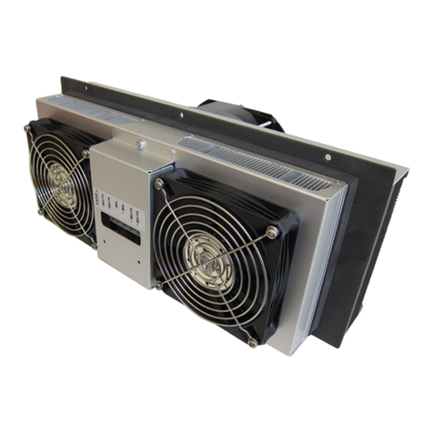
Laird Outdoor Cooler Series Installation instructions

AA-250 Outdoor Cooler Series
Specification and User Manual

2
Table of Contents
Table of Contents.................................................................................................................................. 2
1. Introduction ................................................................................................................................... 3
2. Incoming Inspection ..................................................................................................................... 4
3. General Safety Warning................................................................................................................ 4
4. Technical Specifications .............................................................................................................. 4
4.1 Specifications 5
4.2 Performance Curve 6
4.3 Isometric Drawing 6
5. Installation and Operation Instructions ...................................................................................... 7
5.1 Mounting and Hardware 7
5.2 Schematic 8
6. Serviceability ................................................................................................................................. 9
7. Warranty......................................................................................................................................... 9
8. Return Procedure........................................................................................................................ 10
Revision History
www.lairdthermal.com
Any information furnished by Laird and its agents, whether in specifications, data sheets, product catalogues or otherwise, i
s believed to be (but is not warranted as being) accurate and
reliable, is provided for information only and does not form part of any contract with Laird. All specifications are subject
to change without notice. Laird assumes no responsibility and
disclaims all liability
for losses or damages resulting from use of or reliance on this information. All Laird products are sold subject to the Laird Terms and Conditions of sale (including Laird’s
limited warranty) in effect from time to time, a copy of which will be furnished u
pon request.
© Copyright
2019-2022 Laird Thermal Systems, Inc. All rights reserved. Laird™, the Laird Ring Logo, and Laird Thermal Systems™ are trademarks or registered trademarks of Laird Limited
or its subsidiaries.
REV DATE DESCRIPTION
01
09/14/2014
Initial release
02
03/25/2022
Updated to LTS Format. Performance graph, isometric drawings
updated based on current datasheet

3
1. Introduction
Laird Thermal Systems’ Outdoor Cooler Series is an Air-to-Air thermoelectric cooler assembly that
uses impingement flow to transfer heat. It offers dependable compact performance by cooling objects
via convection and is designed to provide cooling for a wide range of outdoor environments in the
telecom, industrial and kiosk markets. They are intended to work in an open loop system or if
purchased with a bi-polar controller in a closed loop system with feedback control.
Heat is absorbed and dissipated thru high density heat exchangers equipped with air ducted shrouds
and brand name fans. The heat pumping action occurs from custom designed thermoelectric coolers
that achieve a high coefficient of performance (COP) to minimize power consumption.
This product series has been designed to pass rigorous Telcordia test requirements, such as
earthquake resistance, salt fog, wind-driven rain, high temperature exposure and dust contaminants.
This is due to the selection of world class components such as brand fans with the highest degree of
environmental protection, waterproof connectors, heavy duty anodization on the heat exchangers,
overheat protection, and double environmental seals for the thermoelectric coolers.
This manual provides the necessary general information for proper installation and operation that has
been developed to achieve the best results when using a Laird Thermal Systems Outdoor Cooler
Series product.

4
2. Incoming Inspection
Laird Thermal Systems’ Outdoor Coolers are designed, built, and packaged to withstand the shock
and vibration associated with normal transit means by common carriers. Occasionally, improper
handling during shipment may cause damage to the product. Therefore, packages should be opened
promptly and inspected for damage. Any packaging tears, dents, scratches, or loose objects should
be noted on the Freight Bill. If damage is found, an immediate claim must be filed with the freight
carrier. Retain all packing materials. Laird Thermal Systems cannot be responsible for Consignee’s
failure to file a freight claim in a timely manner.
3. General Safety Warning
WARNING
Electrical Shock Hazard
INSTALL UNIT TO CABINET WALL FIXTURE PRIOR TO POWERING DEVICE.
OPERATIONAL VOLTAGE SHOULD COMPLY TO NOMINAL RATING ON LABEL.
ENSURE THAT THERE IS
AN EXTERNAL FUSE IN LINE WITH OUTDOOR COOLER TO PROTECT INPUT POWER
LINES TO UNIT.
4. Technical Specifications
Part Number Nomenclature
Consult with Laird Thermal Systems for custom designed bi-polar controller features or alarms.

5
4.1 Specifications
TECHNICAL
Technology
Thermoelectric coolers, forced air, closed
loop (not mixing with outside air), filter-
less, non-refrigerant
Cooling at dT = 0°C, and nominal / float voltage
1
244/262W (832/894 Btu/hr)
Heating 2
250W (853 Btu/hr)
Voltage (nominal / maximum)
24/28 VDC | 48/56 VDC
Current draw, ±10% (nominal)
12.1 Amps | 6.1 Amps
Grounding (all voltages)
Positive or negative
Weight
6.3 kg (16.9 lbs)
Panel mounting
Through mount
Fan life (L10 at +40°C)
≥70,000 hours
Connector type Terminal block with cage clamp
(12-28 AWG)
Hi-pot testing
707 VDC
ENVIRONMENTAL
Temperature range
3
(external ambient)
-40°C to +55°C (-40°F to +131°F)
Temperature range (internal enclosure)
-20°C to +55°C (-4°F to +131°F)
Degree of protection, enclosure
4
NEMA 4 (IP55)
Degree of protection, unit
5
IP54
Sound level (1m distance)
63 dB(A)
Over-Temp Thermostat (internal/external heat sink)
75°C ± 5°C (optional)
1) Cooling capacities at nominal / float voltage are rated at external temperatures of 35°C and 50°C respectively. Float voltage
is defined at 28 VDC for 24 volt version or 54 VDC for 48 volt version.
2) Heating capacity is rated at external temperature of -40°C, nominal voltage, and ΔT = 45°C.
3) Controller function should not operate the external fan during heating mode. This will pull heat out of the cabinet.
4) The highest environmental protection level requires an external shroud and is defined as the protection level for
the enclosure.
5) Rating for unit without protective shroud.
Note: The specified performance of any Laird Thermal Systems cooling unit is dependent on how it is handled and incorporated
into the final product. This includes elements such as the system design, insulation design, and assembly method. While Laird
Thermal Systems is able to provide general guidelines based upon our experience, it is ultimately the responsibility of the OEM
to validate each product and its performance for its intended use.

6
4.2 Performance Curve
The cooling capacity was conducted at an ambient temperature of 35°C. Performance will deviate
based on ambient temperature condition.
4.3 Isometric Drawing

7
5. Installation and Operation Instructions
Reducing the passive heat load is critical to yield the highest efficiency out of an Outdoor Cooler and
maximize service life. It is important to insulate the walls of an enclosure with as much insulation
material as permissible without interfering with nearby electronics or system level obstructions. Proper
insulation of the enclosure can result in sizing a lower capacity Outdoor Cooler unit and power supply,
which can reduce total system costs.
The Outdoor Cooler is mounted onto a cabinet wall with the “Hot Side” mounted external to the
cabinet. This is required to dissipate heat out of the cabinet. It is also important to have good
ventilation on the hot side to transport heat exhaust away from the cabinet. A minimum of one fan
thickness is required from the wall surface to the exterior face of the fan to allow air to enter into the
fan and transport the exhaust through the ducted shroud.
Outdoor Coolers cool below ambient, so it is important to run them in a cabinet that is sealed from the
outside environment. If the dew point is reached, then moisture in the air will condense onto the cold
side heat exchanger. Access to outside air exchange can accelerate the moisture condensation rate
and cause large amounts of moisture to accumulate on the cold surfaces of the Outdoor Cooler,
which could degrade operation life over time if the system is not designed to drain condensation. It is
recommended to mount the Outdoor Cooler in a vertical orientation, so condensation runs off the cold
side heat exchanger. If the enclosure cannot accommodate this, than the Outdoor Cooler should be
installed at a minimum of a 15 degree angle in horizontal orientation to allow for condensation to run
off the cold side heat exchanger.
The Outdoor Cooler must be protected from vandalism or external forces that may bump up against
unit and cause damage.
5.1 Mounting and Hardware
The enclosure should be sealed from the outside environment by maintaining good compression
between the Outdoor Cooler and cabinet wall. The Outdoor Coolers are designed to be through
mount, so a cut out on the enclosure wall will be required to accommodate the cold side heat
exchanger. Reference the below diagram for mounting hole locations and cold side heat exchanger
dimensions. The cut out should be 2.5 mm’s larger than the cold side heat exchanger. Six mounting
holes are available to fasten the Outdoor Cooler unit to cabinet wall. The mounting holes are
designed to accommodate M6 machine hardware as shown in diagram. External tooth lock washers
are recommended to prevent the Outdoor Cooler from loosening over time

8
5.2 Schematic
Outdoor Coolers come with a durable simple to use cage clamp. Wires should be stripped back 6
mm’s in length and inserted into connector. The connector can accommodate wire sizes of 12 to 28
AWG. For input power to TEM 16 AWG stranded copper wire is recommended. For input power to
fans 18 AWG stranded copper wire is recommended.
Internal schematic of Outdoor Cooler Unit. (24 Volt schematic shown)
1. Connect external fuse in line with input power connector to protect input
power lines from shorting.
2. Input voltage must not exceed rating on label of unit. Maximum ripple current
should not exceed three percent of nominal value.

9
6. Serviceability
No special maintenance is required when using Laird Thermal Systems Outdoor Coolers. For
continued optimal performance and extended life of the unit, it is recommended to clean the
(internal/external) heat sinks and fans periodically as they will accumulate dust from outside
contaminants over time. If a unit is not performing properly consult with Laird Thermal Systems.
7. Warranty
Laird Thermal Systems’ Outdoor Coolers are manufactured in an ISO 9001:2008 facility. Units adhere
to the highest quality standards and are free from defects in material, components, and workmanship.
This warranty covers repair or replacement of product, to be done at a Laird Thermal Systems facility,
for a period of two (2) years from date of shipment. Customer is responsible for shipping product to
Laird Thermal Systems freight prepaid. Laird Thermal Systems in turn will return the warranted
product to customer freight prepaid, if within the time period specified above. Warranty coverage is in
effect when the following operating conditions are continuously satisfied:
•Ambient Temperature Range within -40°C to 55°C.
•Line Voltage variation within plus or minus 12.5% of nameplate rating.
In addition, the following criteria must be met:
•Electrical installation and grounding must comply with local electrical and safety codes.
•Outdoor Cooler must be used in the environment for which it is designed.
•Customer cannot abuse or mishandle the product in any way. Any modifications to the
original unit will also void warranty.
•Compliance to User’s Manual or any other instructional guide provided by Laird Thermal
Systems for the product.
This warranty does not cover the following:
•Applications where product is being misapplied. This includes inappropriate selection of
Outdoor Cooler for the environment and conditions in which it is to be used.
•Damages caused by shipping carrier or any other accident after product has left Laird
Thermal Systems. Shipping claims are the responsibility of the customer and are to be
completed in a timely manner.
•Reimbursement of labor for installation or removal of warranted product, or for parts and labor
resulting from repairs performed by any other source besides Laird Thermal Systems.
This is the complete warranty and is in lieu of any other warranty expressed or implied, including but
not limited to any implied warranty of merchantability or fitness for a particular purpose. Laird Thermal
Systems will in no way be liable for incidental or consequential damage whatsoever or for any other
claims by the customer for damages in connection with Laird Thermal Systems products, even if
advised in advance of the possibility of such damage.
10
8. Return Procedure
All returns must be assigned a Return Materials Authorization number (RMA#) in advance. To start a
return process, simply fill out the form at https://www.lairdthermal.com/about/product-return-policy
Returns received without RMA # may be refused. All returns must be securely packed to prevent
shipping damage and must be clearly marked with the RMA# on the box. Consignor shall pay freight
charges on all returns.
For any questions, please contact us via the website https://www.lairdthermal.com/contact
Other manuals for Outdoor Cooler Series
1
This manual suits for next models
1
Table of contents
Other Laird Accessories manuals

Laird
Laird Sentrius BT610 User manual

Laird
Laird Sentrius RS191 User manual

Laird
Laird Sentrius RS1 Series User manual

Laird
Laird Outdoor Cooler Series Installation instructions

Laird
Laird WL 3000 User manual

Laird
Laird Sentrius RS1 Series User manual

Laird
Laird Sentrius BT610 User manual

Laird
Laird Sentrius BT510 User manual

Laird
Laird AA-230 Series Installation instructions