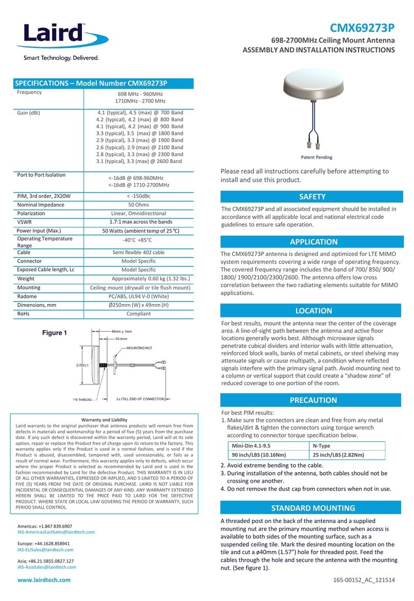
Pleasereadallinstructionscarefullybeforeattemptingto
installandusethisproduct.
SAFETY
The AP-ANT-40 and all associated equipment should be installed in
accordance with all applicable local and national electrical code
guidelinestoensuresafeoperation.
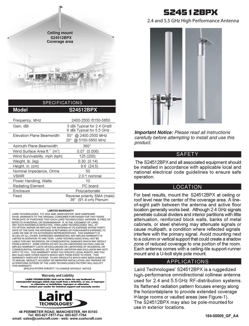
Figure 1
SPECIFICATIONS – Model Number AP-ANT-40
Frequency 2300-2700 MHz
4900‐6000 MHz
Gain (dBi) 4.5(typical),5.0(max)@2300Band
3.7(typical), 4.0 (max) @2700 Band
5.0(typical), 6.0 (max) @ 4900 Band
5.0(typical), 6.0(max)@6000Band
Portto PortIsolation <‐16dB@ 2300‐2700 MHz
<‐20dB@4900‐6000 MHz
NominalImpedance 50Ohms
Polarization Linear,Omnidirectional
VSWR 1.5:1 typical (2.0:1 max)@ 2300 band
1.5:1 typical (2.0:1 max)@ 2700 band
1.5:1 typical (2.0:1 max)@ 4900 band
1.5:1 typical (2.0:1 max)@ 6000 band
Power Input (Max.) 10 Watts (ambient temp of 25°C)
Operating Temperature
Range ‐40°C+ 85°C
Connector Model Specific
Exposed Cable length ModelSpecific
Weight Approximately0.45kg
Mounting Ceiling mount (drywall or tile flush mount)
Radome PC/ABSV‐0(White)
Dimensions, mm 178 mm(Dia.)x32 mm(H)
RoHs Compliant
AP-ANT-40
2300-2700 / 4900-6000 MHZ
Omni‐DirectionalCeilingMountAntenna
ASSEMBLYANDINSTALLATIONINSTRUCTIONS
165-00231_AB
PRECAUTION
1. Makesuretheconnectorsarecleanandfreefromanymetal
flakes/dirt&tightentheconnectorsusingtorquewrench
accordingtoconnectortorquespecificationbelow.
2. Avoid extreme bending to the cables.
3. During installation of the antenna, cables should not be
crossing one another.
4. Do not remove the dust cap from connectors when not in used.
TheAP-ANT-40antennaisdesignedandoptimizedfor WLAN
MIMO system requirements covering a wide range of operating
frequency. The covered frequency range includes the
bandof2300-2700/4900-6000 MHz.Theantennaofferslowcross
correlationbetweenthe fourradiatingelementssuitableforMIMO
applications.
APPLICATION
Forbestresults,mounttheantennanearthecenterofthecoverage
area.Aline‐of‐sightpathbetweentheantennaandactivefloor
locationsgenerallyworksbest.Althoughsignalspenetratecubical
dividersandinteriorwallswithlittleattenuation,reinforcedblock
walls,banksofmetalcabinets,orsteelshelvingmayattenuate
signalsorcausemultipath,aconditionwherereflectedsignals
interferewiththeprimarysignalpath.Avoidmountingnexttoa
columnorverticalsupportthatcouldcreatea“shadowzone”of
reducedcoveragetooneportionoftheroom.
LOCATION
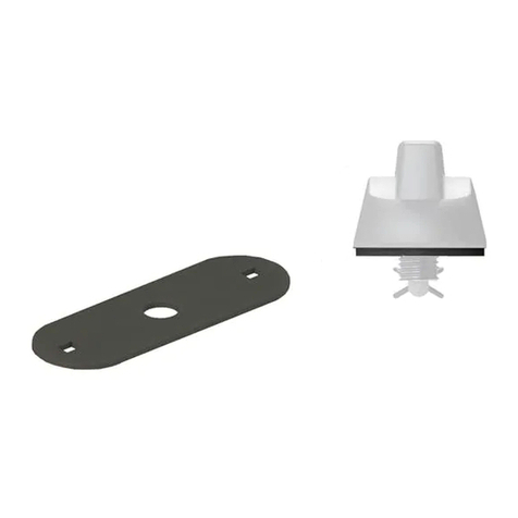
Athreadedpostonthebackoftheantennaandasupplied
mountingnutaretheprimarymountingmethodwhenaccess
isavailabletobothsidesofthemountingsurface,suchasa
suspendedceilingtile.Markthedesiredmountinglocationon
thetileandcutaø40mm(1.57”)holeforthreadedpost.Feed
thecablesthroughtheholeandsecuretheantennawiththe
mountingnut.(Seefigure1).
STANDARDMOUNTING
Patent Pending
AP-ANT-40


