Yagi Tuning & Assembly Data
Introducon
Your new Laird Yagi antenna has been designed for accuracy, durability and value. Electrical designs are
opmized using the latest in computer aided technology. For fully welded and anodized models, all crical
element to boom joints are welded, the enre antenna is anodized, a heavy duty anodized cast mounng kit
is included and the antenna is internally matched. This provides for extremely high durability, resistance to
corrosion and an accurate radiaon paern.
Warning! Use extreme cauon when installing this antenna. Electrocuon and/or death can occur if this
antenna comes in contact with or comes near electric power lines.
400 to 1000 MHz Pre-Assembled & Welded Yagi Antennas
The internally matched, fully assembled and welded Yagi antenna for frequencies above 400 MHz is factory
tuned to the middle of the operang frequency range. The antenna features broad bandwidth and low VSWR
across the band. No further adjustment to the antenna is necessary. It is suggested, however that before
permanently mounng the antenna it should be checked for low VSWR. This can be done by temporarily
posioning the antenna on a mast at least four (4) feet above the ground and away from surrounding objects.
Apply RF power to the antenna and check for resonance.
Upon installaon of the antenna, aer installing the coax to the end of the boom, be sure to relieve the strain
on the feed joint. This can be accomplished by looping the coax to the mast, secure the coax to the mast with
a nylon e and then route it down the mast to the nal amplier.
Important Note: Insert boom into the mounng bracket; use hex bolts to ghten securely. Do not exceed 4-6
-lbs of torque on the hex bolts.
VHF User-Assembled Yagi Antenna
Follow the instrucons listed below to assemble your VHF Yagi Antenna:
Assembly Steps
1. Unpack the antenna and locate the following parts:
Boom (1-1/4" dia. for ve element model, 7/8" dia. for three element model)
3/8" Diameter Elements (Y—3 = three elements, Y—5 = ve elements)
Gamma Match parts bag
Mounng Bracket parts bag
2. To assemble a factory tuned model, locate the 3/8" diameter elements and proceed to step ve.
3. Field tunable models are shipped with the 3/8" diameter elements trimmed to the lowest frequency. In
order to tune your antenna to another frequency in its range, locate the elements and proceed to step
four.
4. Find the proper element dimension chart for your antenna on the next page and trim each element
according to your operang frequency. Use care to trim equal lengths from each end of each element
as there is a threaded mounng hole at the center. This mounng hole must be at the center of the
element aer trimming!
5. Insert the elements into their respecve locaons through the boom starng with R1 (the reector element)
in the hole closest to the mounng holes. Then insert Dr, D1, etc., in that order. Secure the elements with
the stainless steel 10-32 hex bolts and #10 lock washers provided. Complete the element installaon by
inserng the black end caps onto the ends of each element.
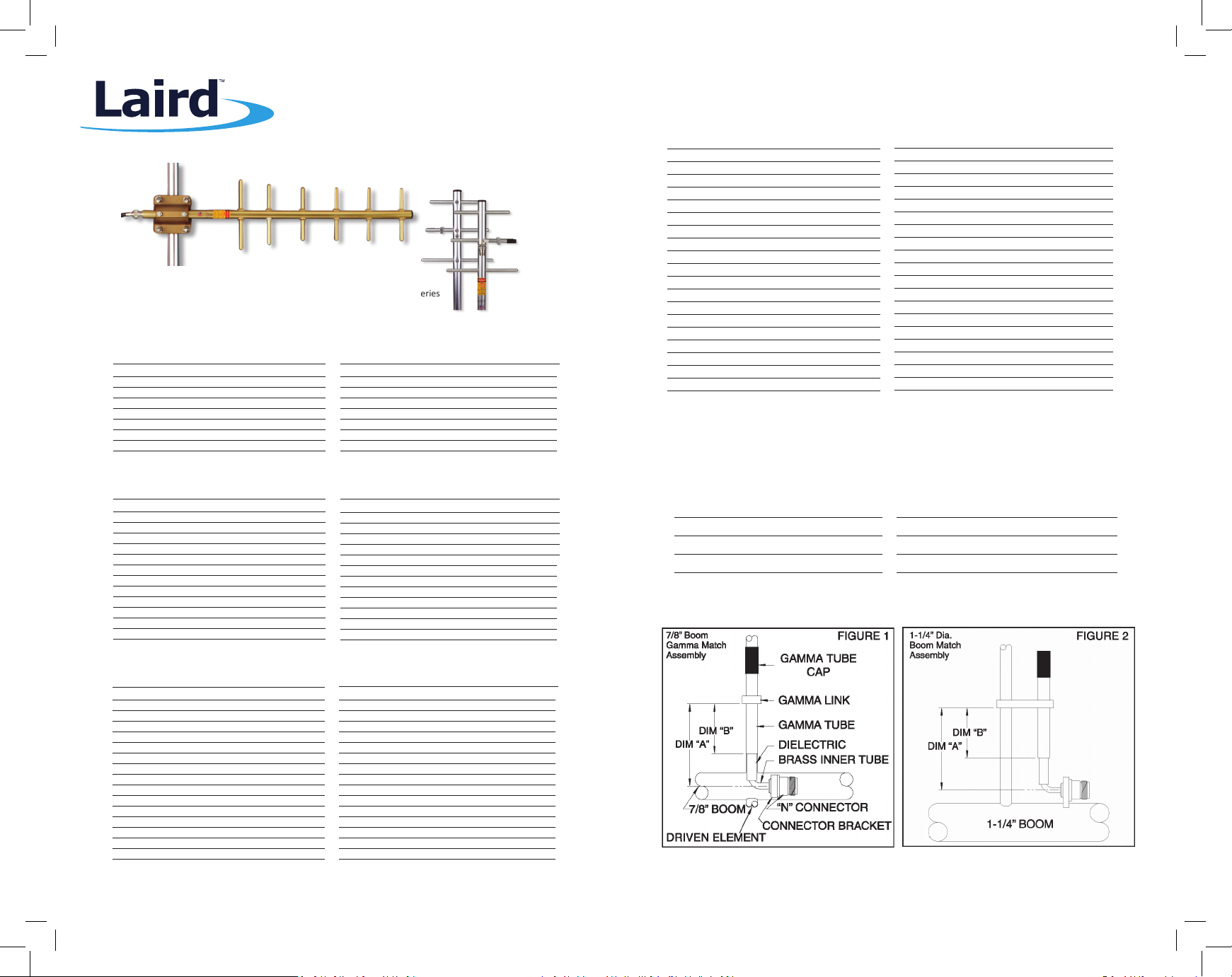
6. Locate the Connector/Brass tube assembly in the Gamma Match parts bag and insert the assembly tube
rst through the connector bracket then thread the connector into the bracket. Be sure to ghten the
connector fully. A drop of Lockte® or other threadlock may be used on the connector threads to elimi-
nate the possibility of the connector loosening. See Figure 1 (7/8" boom) or Figure 2 (1-1/4" boom) on
the back page for proper orientaon.
7. Slide the Gamma Link onto the driven element and assemble the Gamma Match as shown in Figure 1 or
2. Set dimensions “A” and “B” to those shown in Table 1. Seng the match to the dimensions shown
for your antenna is a good starng point which will enable you to quickly ne tune later. Complete the
assembly by aaching the end cap onto the end of the gamma tube. The antenna is now ready for Final
Tuning.
Final Tuning
Before nal installaon of the antenna, temporarily set it up in a clear area at least 6 feet above the ground.
Apply RF power to the antenna and check for low VSWR while performing each of the following steps:
A. First, loosen the set screw with the allen key provided and make a slight adjustment to
the aluminum gamma tube for lowest VSWR.
B. Next, adjust the gamma link along the driven element for lowest VSWR.
C. Repeat the above steps unl the best match is achieved.
D. Return to the dimensions shown in Table 1 if there is any trouble achieving a good match.
Important Note: Upon final installation, be sure the gamma match points up towards the
sky. Insert boom into the mounting bracket; use hex bolts to tighten securely. Do not exceed
4-6 -lbs of torque on the hex bolts.
Weather Proong
To weatherproof the coax connector and coax cable, slide the sealtube 3 (not included) onto the coax cable.
Tighten the coax connector and then posion the sealtube over the connector. Heat sealtube with a lighter
or other device, taking care not to overheat the tubing. Finish up with a coang of 3M® Skotchkote®for years
of performance.
Remember: SURROUNDING OBJECTS, EARTH GROUND AND THE TUNING ENGINEER ALL HAVE A GREAT
EFFECT ON VSWR AND RESONANT FREQUENCY! Obstacles in the paern of the antenna can shi the resonant
frequency lower by up to 1 MHz.
Warranty
Laird warrants to the original purchaser that our antennas will remain free from defects in materials and work-
manship for a period of one year from the purchase date. If any such defect is discovered within the warranty
period, Laird will at its sole opon, repair or replace your product free of charge. This warranty applies only
if the product is used as designed, and is void if the product is abused, disassembled, tampered with, used
unreasonably, or fails as a result of normal wear. Furthermore, this warranty applies only to defects which
occur where the proper product is selected as recommended by Laird and is used in the fashion recommended
by Laird. This warranty is in lieu of all other warranes, expressed or implied, and is limited to a period of
two years from the date of original purchase. Laird is not liable for incidental or consequenal damages of
any kind. Any warranty extended herein shall be limited to the price paid to Laird for the defecve product.
Where the period of warranty is governed by state or local law such period shall control.
WARNING!
YOU CAN BE KILLED IF THIS ANTENNA COMES NEAR OR IN CONTACT WITH AN ELECTRIC POWER LINE.
ALWAYS USE CAUTION WHEN INSTALLING THIS ANTENNA. STAY AWAY FROM ALL OVERHEAD WIRES OF ANY KIND.
©Laird - All Rights Reserved
Tel: 847.839.6000 • Fax: 847.839.6036 • www.lairdtech.com