Laird WL 500 Installation instructions

WL 500
Specification and User Manual

2
2
Laird Thermal Systems s.r.o.
Operation Manual
Date: 03/10/2022
Version: 1.1
WL 500
1505.00
www.lairdthermal.com
Any information furnished by Laird and its agents, whether in
specifications, data sheets, product catalogues or otherwise, is believed to be (but is not warranted as being) accurate and
reliable, is provided for information only and does not form part of any contract with Laird. All specifications are subject
to change without notice. Laird assumes no responsibility and
disclaims all liability for losses or damages resulting from use of or reliance on this information. All Laird products are s
old subject to the Laird Terms and Conditions of sale (including Laird’s
li
mited warranty) in effect from time to time, a copy of which will be furnished upon request.
© Copyright
2019-2022 Laird Thermal Systems, Inc. All rights reserved. Laird™, the Laird Ring Logo, and Laird Thermal Systems™ are trademarks or registered trademarks of Laird Limited
or its subsidiaries.

3
3
Laird Thermal Systems s.r.o.
Operation Manual
Date: 03/10/2022
Version: 1.1
WL 500
1505.00
Table of Contents
Revision History.................................................................................................................................... 4
1. Description..................................................................................................................................... 5
2. Safety Precautions........................................................................................................................ 5
2.1 Electrical Danger ..................................................................................................................... 5
2.2 Safe Operation ........................................................................................................................ 5
2.3 Environmental Issues .............................................................................................................. 5
3. Technical Data ............................................................................................................................... 6
3.1 Physical Dimensions ............................................................................................................... 6
3.2 Performance Data ................................................................................................................... 6
3.3 Mounting.................................................................................................................................. 6
3.4 Environmental Specifications .................................................................................................. 6
3.5 Settings ................................................................................................................................... 6
4. Installation Procedure .................................................................................................................. 7
5. Settings .......................................................................................................................................... 8
5.1 Flow Switch ............................................................................................................................. 8
6. Maintenance................................................................................................................................... 8
6.1 Heat Exchanger ...................................................................................................................... 8
7. Liquid Circuit Diagram.................................................................................................................. 9
8. Electronic Schematic.................................................................................................................. 10
9. Spare Parts .................................................................................................................................. 11

4
4
Laird Thermal Systems s.r.o.
Operation Manual
Date: 03/10/2022
Version: 1.1
WL 500
1505.00
Revision History
REV
DATE
DESCRIPTION
1.0
01-02-2009
Initial release
1.1
03-10-2022
Updated pictures. Updated part numbers for spare parts. Rewritten on
new Operation manual template. Moved Safety Precautions from front
page to chapter 2. Corrected Technical data.

5
5
Laird Thermal Systems s.r.o.
Operation Manual
Date: 03/10/2022
Version: 1.1
WL 500
1505.00
1. Description
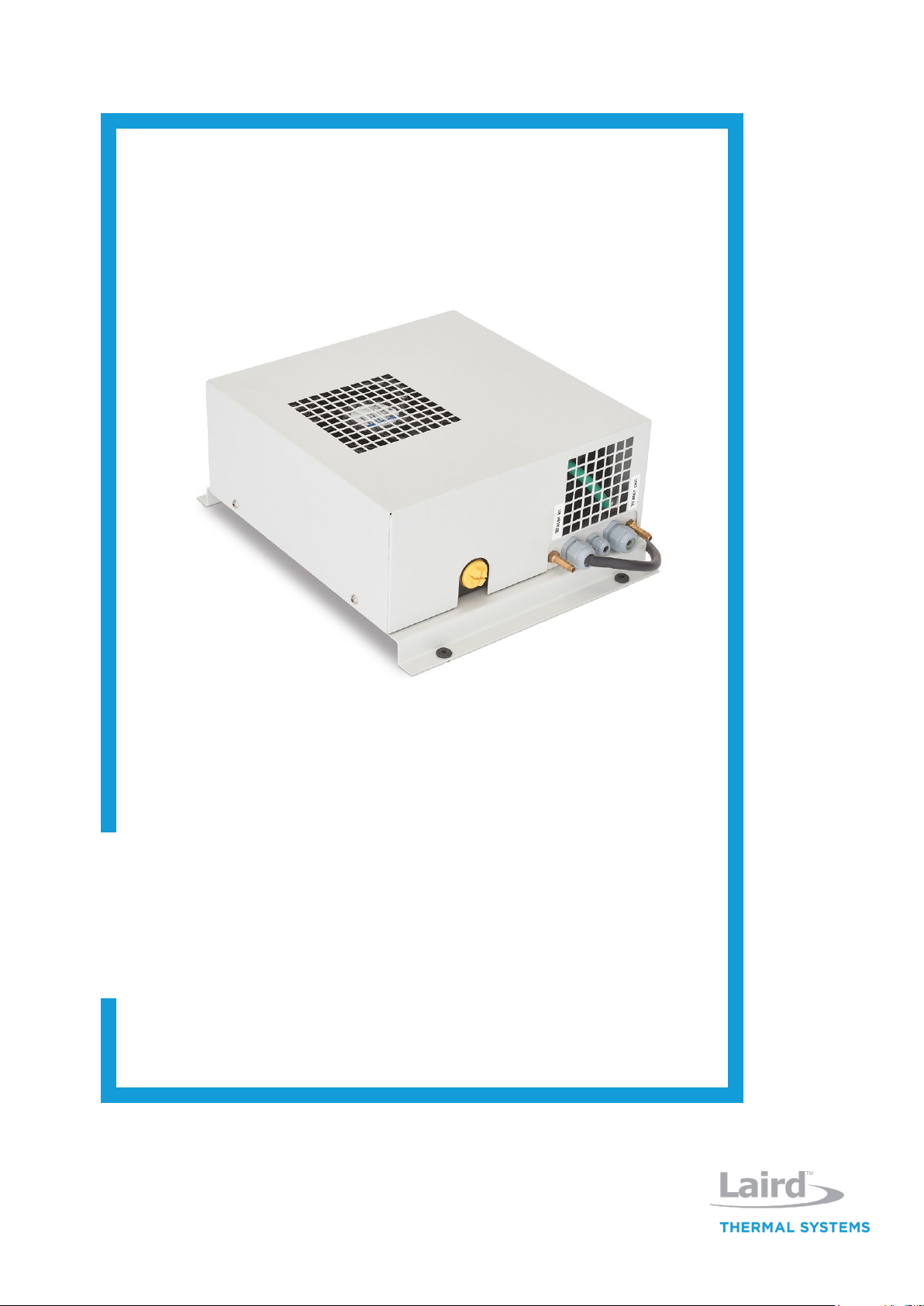
The WL 500 cooling unit is intended to remove heat from a liquid circuit. The coolant can be either
water or a mixture of water and water-glycol (antifreeze). Water circulates in a closed loop between
the ambient cooling system and a cold plate at the heat source. Heat is removed from water by an air-
cooled heat exchanger. The capacity of the cooling unit is dependent on the temperature differential,
which is defined as the difference between the ambient temperature and the water outlet temperature.
The cooling unit is designed to remove 500 W of heat at a temperature differential of 13°C. The water
inlet and water outlet are marked as Water in and Water out.
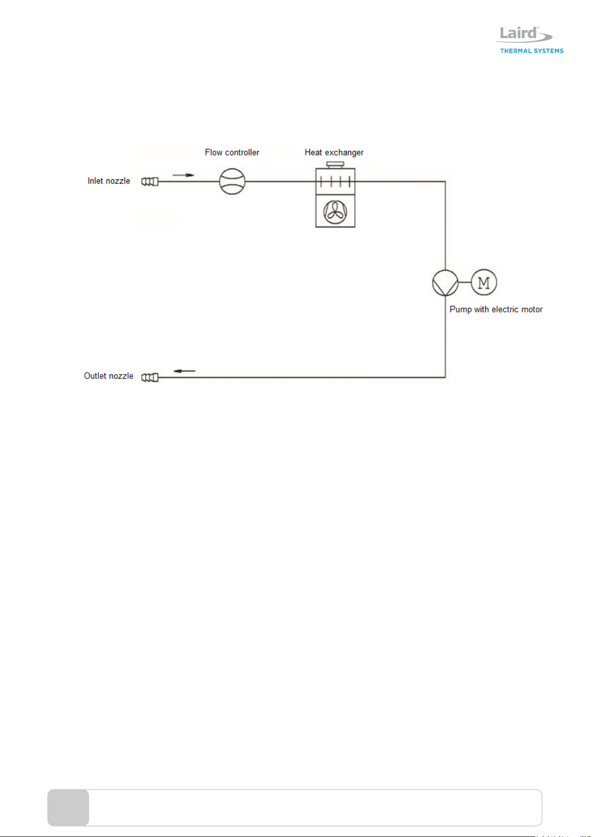
The maximum forward pressure is limited by a bypass valve, which has been integrated into the
pump. The coolant flow is controlled by a flow switch that opens when flow falls below a set rate.
Cooling hoses supplied by user are connected to threaded nozzle that can accommodate an 8 mm
hose ID.
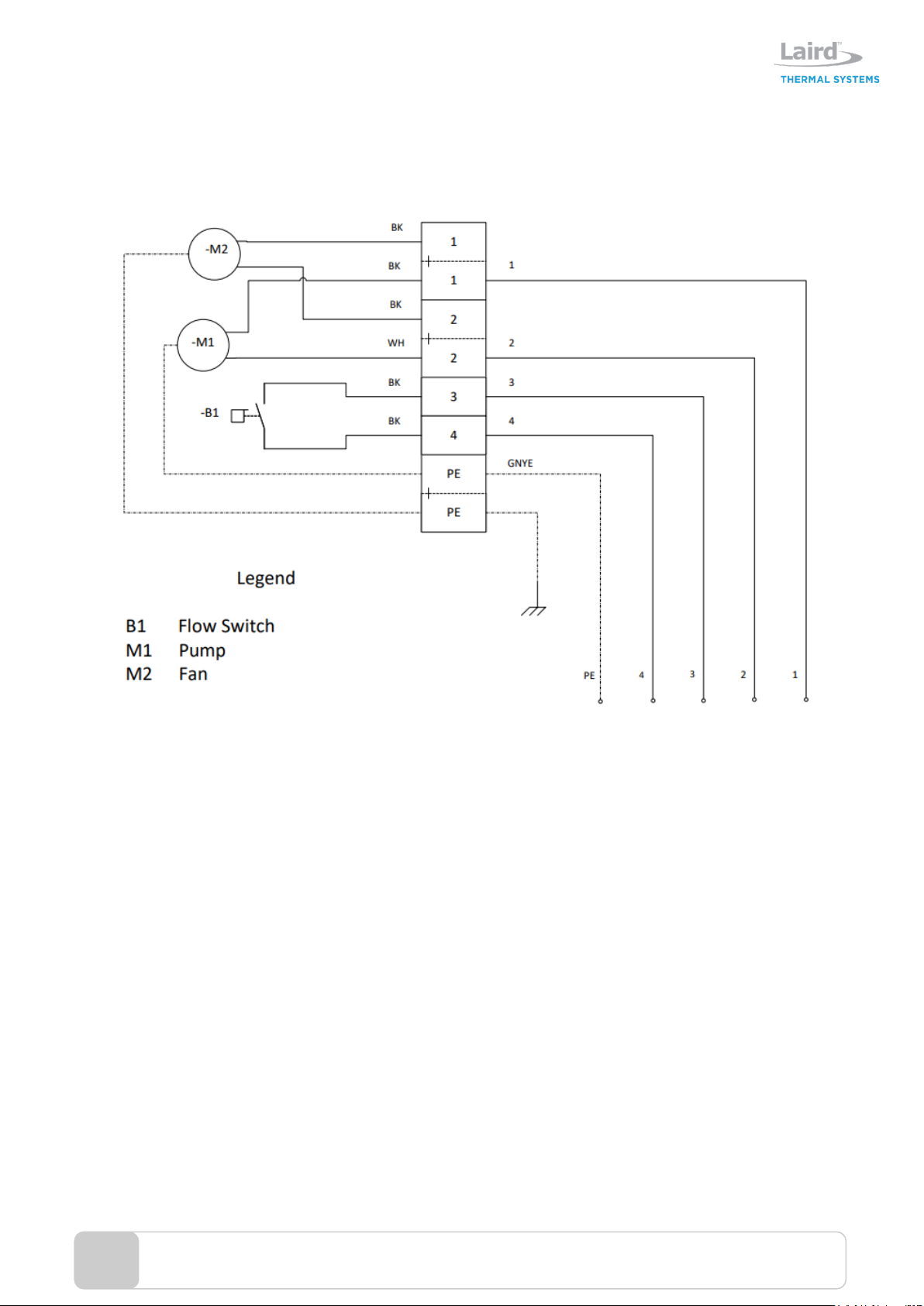
The water flow is monitored by an adjustable flow switch. The signal of the flow switch is available at
a potential free safety circuit. The permissible contact rating for the safety circuit is 125 VAC/1A/50
VA.
A bypass valve limits the water pressure.
Note: Flow switch and bypass valve are adjusted at factory and set according to specification.
2. Safety Precautions
Note: Read manual before operating the cooling unit.
2.1 Electrical Danger
Work on electrical installations must be carried out only by trained and authorized electricians
Input power must be rated 230 VAC at 50/60 Hz.
Before starting any service work on the cooling unit, please disconnect from the main power
source.
2.2 Safe Operation
Use Water or Water/Glycol as coolant.
Run the cooling unit at the correct coolant level, otherwise the pump might degrade, and cooling
capacity will be reduced.
Use cooling hoses that can handle max pressure of the liquid circuit and is resistant to corrosion
from coolant.
Never operate the unit if it is damaged or leaking.
2.3 Environmental Issues
Environmentally hazardous substances must be used or disposed of according to regional
regulations.
When dealing with working fluids, always be aware of the safety data sheet of the corresponding
manufacturer and use appropriate personal protective gear.

6
6
Laird Thermal Systems s.r.o.
Operation Manual
Date: 03/10/2022
Version: 1.1
WL 500
1505.00
3. Technical Data
3.1 Physical Dimensions
Length: 370 mm
Width: 307 mm
Height: 151 mm
Weight: 11 Kg without coolant
Coolant capacity: 1.7 L
3.2 Performance Data
Cooling capacity: 500 W
Flow rate: 2.3 L/min at 2,5 bar
Supply voltage: 230 V / 50/60 Hz
Current consumption: 1.2 A
Noise level: ≤ 60 dB(A) distance 1 m in any direction
Contact rating of safety circuit (make): 250 Vac, 0.5 A, 50 VA
3.3 Mounting
Mount on vertical wall with filling port facing up.
Mechanically fasten with four M5 x 40 mm screws and washers
3.4 Environmental Specifications
Ambient temperature: + 5°C...+ 40°C
Storage temperature: - 25°C...+ 70°C (storage without water)
Air humidity: 20%...80%
3.5 Settings
Maximum forward pressure: 3.5 bar
Flow switch open: ≤ 0.9 l/min

7
7
Laird Thermal Systems s.r.o.
Operation Manual
Date: 03/10/2022
Version: 1.1
WL 500
1505.00
4. Installation Procedure
1 Vertically wall-mount the cooling unit with the filling
port in an upright position.
Hole pattern: width 216 mm, height 352 mm.
2 Remove the yellow transportation cap, and the sheet
metal cover.
3 Insert mains power cable and connect it to the
terminals according to the terminal diagram; use a 3
mm screwdriver to connect the wires to terminal
block. Remount the cover.
4 Connect the external hoses supplied by the user.
5 Fill the cooling unit with approximately 1.7 L of
coolant and install the red filling level indicator cap.
Note: The level must always be
between MAXIMUM and MINIMUM
Note: Cooling performance will be reduced, and pump will degrade if filling level is less than
Minimum.
6 Allow the cooling unit to run for 10 minutes to deaerate the coolant circuit.
7 Check the coolant level as indicated by the cap. If necessary, add additional coolant.
Filling level MAXIMUM
Filling level MINIMUM

8
8
Laird Thermal Systems s.r.o.
Operation Manual
Date: 03/10/2022
Version: 1.1
WL 500
1505.00
Set screw
5. Settings
5.1 Flow Switch
The flow switch is set to open at 0.9 lpm. If it is necessary to adjust this setting, then perform the
following:
1 Disconnect the cooling unit from the main power source.
2 Remove the complete cover.
3 Adjust set screw to:
-Increase the flow rate set point by adjusting the screw clockwise.
-Decrease the flow rate set point by adjusting the set screw counterclockwise.
6. Maintenance
Check the coolant level regularly and refill if necessary.
6.1 Heat Exchanger
To retain maximum cooling capacity, the heat exchanger of the cooling unit must be kept clean.
Check heat exchanger every 3 months for cleanliness.
If cleaning is required perform the following:
1. Disconnect the cooling unit from the main power source.
2. Remove the cover.
3. Clean the heat exchanger with compressed air, a damp cloth, or a vacuum cleaner.
4. Mount the cover.

9
9
Laird Thermal Systems s.r.o.
Operation Manual
Date: 03/10/2022
Version: 1.1
WL 500
1505.00
7. Liquid Circuit Diagram

10
10
Laird Thermal Systems s.r.o.
Operation Manual
Date: 03/10/2022
Version: 1.1
WL 500
1505.00
8. Electronic Schematic

11
11
Laird Thermal Systems s.r.o.
Operation Manual
Date: 03/10/2022
Version: 1.1
WL 500
1505.00
9. Spare Parts
WL 500 (1505.00)
No.
Description
Part number
1
Motor
2060.00
2
Pump
2061.00
3
Fan
2062.00
4
Filling cap
2063.00
4
3
1
2
Table of contents
Popular Industrial Equipment manuals by other brands

Nidec
Nidec LAROY-SOMER LSA 50.2 Installation and Maintenance

TriangleTube
TriangleTube MAXI-FLO MF 350 PT Series Installation and maintenance manual

Pronomic
Pronomic Squeeze&Turn 19472 user manual

Omron
Omron AnyFeeder Series Integration guide

Perma
Perma NOVA installation guide

SMC Networks
SMC Networks ZXP7 X1 KA Series Operation manual

EAS Electric
EAS Electric ESUN150 instruction manual

Hoval
Hoval ST1 INSTRUCTIONS FOR INSTALLATION, COMMISSIONING AND MAINTENANCE

Trane
Trane AFDH installation instructions

Mechanical Advantage
Mechanical Advantage Sambo SB-V Series User instructions

PASCO
PASCO TD-8577 instruction manual

ABB
ABB HT562921 Operation manual