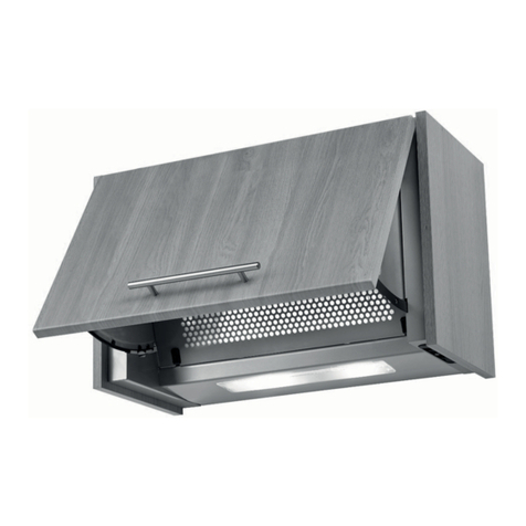
Lamona HJA2230 Manual

60cm Integrated
Extractor
HJA2230
HJA2240
Installation & Operating
Instructions

Environmental note. 2
IMPORTANT SAFETY INFORMATION. 3 - 4
Know Your Extractor. 5 - 6
5
Operating your extractor. 6
Control panel. 6
Care and Cleaning. 7 - 8
General cleaning. 7
The grease 7
Fitting the carbon 7
Changing a light bulb. 8
Installation. 9 - 14
Before beginning installation. 9
Ducted out or recirculation? 10
Mounting the extractor. 11
Decor door installation. 12
Door weight adjustment 13
Fitting the bottom trim 13
Completing the installation 13
Electrical connection 14
Something Wrong with your Extractor? 15
Contact details Rear cover
• Contents 2
Environmental Note:
Before discarding an old appliance, switch off and disconnect it from the
power supply. Cut off and render any plug useless. Cut the cable off di-
rectly behind the appliance to prevent misuse. This should be undertaken
by a competent person.

Your safety is of the utmost importance; please make sure that you read this
instruction booklet before attempting to install or use the appliance.
electrician or competent person.
•The hood must be installed in accordance with the installation instructions
and all measurements followed.
•If the cooker hood is installed for use above a gas appliance then the
provision for ventilation must be in accordance with the Gas Safety Codes
of Practice BS.6172, BS.5440 & BS.6891 (Natural Gas) and BS.5482 (LP
Gas) 1994, the Gas Safety (Installation & Use) Regulations, the Building
Regulations issued by the Department of the Environment, the Building
Standards (Scotland) (Consolidated) Regulations issued by the Scottish
Development Department.
•It is dangerous to alter the or to modify this product; do not
tamper with it or attempt to modify the appliance in any way.
•When installing the hood, the following distances must be observed
between the top of the worktop and the bottom of the cooker hood:
Recommended: 750 mm
Minimum: 700 mm
•When installed between adjoining wall cabinets, the cabinets must not
overhang the hob.
•The edges of the cooker hood may be sharp – handle your appliance with
care, especially during installation and cleaning.
•If the room where the cooker hood is to be used contains a fuel burning
appliance such as a central heating boiler then its must be of the
sealed or balanced type.
•If other types of or appliances are ensure that there is an
adequate supply of air in the room.
•When the hood is being used in its ducted-out mode, ensure that the
ducting is retardant and that there are no bends sharper than 90
degrees as this will reduce the of the hood.
• Important Safety Information 3
•Keep young children from using, playing with or tampering with the cooker
hood. Older children and persons should be supervised if they are
using the cooker hood.
•Your cooker hood is for domestic use only.
•Please dispose of the packing material carefully; children are especially
vulnerable to it.
•Never leave frying pans unattended during use as overheated fats and oils
might catch
•The cooker hood should not be exposed to a direct heat source from the
cooking device underneath it, i.e. a naked from a gas burner or heat
from electric hotplates without a pan on them.
•Never cook under this cooker hood.
•Always put lids on pots and pans when cooking.
•The manufacturer refuses to accept any responsibility for damages arising
from a failure to observe the safety advice contained in this instruction
booklet.
•Remember that when in ducted-out mode, your cooker hood is removing air
from your room; ensure that proper ventilation has been provided.
•Warning - Always ensure that the cooker hood has been disconnected
from the power supply before carrying out any work on the hood,
including replacing light bulbs.
•Do not connect the ducting system of this appliance to any existing
ventilation system which is being used for any other purpose.
•Do not install above a cooker with a high level grill.
•The light on this appliance should only be used during operation of the
cooker hood. It should not be left on permanently and used as a room
lighting source.
•Do not attempt to use the cooker hood if it is damaged in any way.
Never attempt to use it without the grease or if the are
excessively greasy!
• Important Safety Information 4

5
Dimensions:
Extractor width: 600mm
Decor door height: 385 - 700 mm
Decor door weight: 7kg max.
• Know Your Extractor
Features:
•Slider control operation.
•Door position extractor control.
•3 speed extraction.
•1 x 40W light.
• Ducted-out or recirculation modes.
•Grease
•Carbon HJA2907 (optional for recirculation mode only)
HJA2230 HJA2240
•Max. Extraction capacity: 220 m³/hr 399 m³/hr
•Electrical Supply: 220-240V, 50Hz 220-240V, 50Hz
•Max. Appliance Input Power: 140W 240W
•Motor Input Power: 100W 200W
•Fuse Rating: 3A 3A
•Lamp type: 1 X 40W E14 1 X 40W E14

6• Operating Your Extractor
Door Operation
The extractor can be operated by leaving the motor slider on setting 1, 2 or
3 and opening / closing the extractor door. The fan motor will switch off when
the decor door is closed and will resume at the last speed set when the door is
pulled open. The same applies to the light, if the slider is left on position 1.
IMPORTANT:
Ideally you should turn on your hood ten minutes before you start to cook, or at
the very least when you begin cooking. you should also run your hood for ten min-
utes after you have cooking.
Control Panel:
Slider A: Operates the light
0 is the off position.
1 is the on position.
Slider B: Controls the motor speed.
0 is the off position.
1 is the lowest fan speed.
2 is the medium fan speed
3 is the highest fan speed.
0 1
0 1 2 3
A
B

7• Care and Cleaning
IMPORTANT: BEFORE CLEANING, ALWAYS ENSURE THAT YOU HAVE
SWITCHED YOUR COOKER HOOD OFF AT THE MAINS SWITCH.
•Clean the external parts of your cooker hood with mild liquid detergent and
a damp cloth.
•Never use abrasive powder, corrosive solvents or brushes.
•Never insert pointed objects into the motor’s protective grid.
•Ifyou are using the appliance in recirculation mode, then be sure to replace
the carbon at the recommended interval (see ‘The Carbon Filter’
below).
The Grease Filter
•Open the extractor door.
•Slide the grease upwards
slightly then outward at the bottom.
• The grease is retained in place
with a metal spring clip at the top of
the extractor and two plastic lugs at
the bottom.
•Your cooker hood includes a grease
which helps to stop grease
particles to protect your kitchen &
furniture from greasy residues.
•The grease may become a risk if it becomes saturated with a
greasy residue.
•To prevent a hazard, the should be cleaned regularly. Depending
on use, this should be done every 10-15 days or at least once a month,
using hot water and normal washing-up detergent.
•DO NOT WASH THE GREASE FILTER IN A DISHWASHER.
The Carbon Filter
• Grease have a limited live and should be replaced every 6 months
depending on use.
• A build up of grease could cause a hazard.
• Remove the grease as described above.
• Remove the carbon to each motor housing and replace with one
(part no. HJA2906).
• the grease

8
Changing light bulb
IMPORTANT: Before attempting to change a light bulb, you must
ensure that you have disconnected the cooker hood from your
mains supply.
•Use a screwdriver to remove the screw securing the cover on the
underneath of the cooker hood (as shown in the line drawing above).
•Prior to touching the light bulb ensure that it has cooled down.
•Unscrew the light bulb that needs to be replaced and insert a new E14
40W (max) olive shaped bulb.
•If the light still does not work, make sure that the bulb is correctly into
their housings before you call for technical assistance.
the cover and secure it in place using a screwdriver.
• Care and Cleaning

9
We recommend that at least two people install this hood.
YOUR COOKER HOOD SHOULD ONLY BE CONNECTED TO YOUR MAINS
SUPPLY AFTER COMPLETION OF THE INSTALLATION PROCESS
Before beginning the installation
•Check that the product purchased is of a suitable size for the chosen
installation area. In addition check that there is an electrical socket
available that will be accessible once the hood is mounted. If the product
is going to be used in extraction mode, there should also be space to
connect a ducting hose to the outside.
•If possible, disconnect and move freestanding or slot-in cookers from their
position, to provide easier access to the rear wall and ceiling. If this is
not possible, then a thick, protective covering should be placed over the
worktop, hob top or cooker. This will help to protect these surfaces from
damage and debris.
•Select a surface for assembling the cooker hood and cover the surface
with a protective covering.
•IMPORTANT: Please refer to the information on page 3 regarding the
minimum height required between the hob top and the underneath of
the cooker hood.
•The extractor is designed to be installed between two wall units spaced
exactly 600 mm apart at an appropriate height above the hob unit.
• Installation

10
Ducted out or Recirculating ?
In ducted-out mode, the stale air will be taken out of the room via external
ducting. In recirculation mode, stale air is taken via the grease and
passed through a charcoal to remove odours.
Recirculating Ducted-out
For optimum performance, we recommend that the cooker hood is connected
to external ducting. If the appliance is to be ducted out:
• Mark a position that is suitable and will be accessible once the cooker
hood is installed, cut out a circle measuring 130 mm in diameter. This
discharge outlet should be suitable for cooking vapours. It should have a
cross section of at least 150 cm².
•Fit
a
suitable ducting terminal (not supplied) to the wall and connect a 125
mm ducting hose (not supplied) to the terminal.
•Connect the other end of the ducting hose to the top of the cooker hood.
•The
maximum distance between the cooker hood and your discharge
outlet should be 3 metres, with one 90 degree bend. For each additional
90 degree bend, the maximum distance is reduced by a metre.
• Installation

11
• Installation
Mounting the Extractor
•Mark,drill and the top screws into the
adjacent wall unit side panels at 15mm from
the top and 30mm from the front of the wall
unit as shown. Leave a gap of 5 mm between
the heads of the screws and the wall unit side
to allow the extractor to be hung. The distance
between the screw and the
cooking surface should no
less than 1040mm.
•Hang the cooker hood on
the screws between the two
cupboards.
•Push the fan-shaped door frames fully closed, line up the door frames 2 mm
in front of, and parallel with, the front edges of the adjacent wall units (not
the doors) and mark the positions of the lower screws.
•Remove the extractor, drill the two lower holes and re-hang the
extractor.
•Ensure that the extractor is lined up correctly with the adjacent wall units,
and tighten the two lower screws and fully tighten the two top screws.
Make sure all four screws are well
•Connect the air-outlet board and, if the appliance is being ducted out, the
air-outlet tube.
5mm
36
02
15
30

12• Installation
Decor Door Installation
•The door should be no less than 16 mm
thick, 385 - 700 mm high, and weigh no
more than 7 kg.
•The door frames are located in two curved
plastic slides on each side of the extractor
body and are prevented from being pulled
out too far by plastic limit clips which are
accessible after removal of the perforated
grease
•Take care not to drop the frame, pull lightly
on the plastic limit clips ‘1’ while opening
the door frames ‘2’. Once the door frame
has cleared the plastic clip, the door frame
can then be removed from the body of the extractor.
• Lay the decor door face down on a protective surface, accurately mark and
pilot drill the 4 positions.
•Check that the screws are not too long for the decor door, to prevent
damage to the door front and secure the door frames to the door, ensuring
that the frames are symetrically positioned on the decor door.
the assembly of decor door and door frames onto the extractor
ensuring that all four plastic slides are correctly located. Once the door
is fully closed, the plastic limit clips should once again prevent accidental
removal of the door frame from the appliance.
• If the upper edge of the door is not aligned with the upper edges of the
adjacent cabinet doors adjust using the 4 screws.
• Once aligned, secure the door in position using a further 4 screws.
21

13• Installation
Door Weight Adjustment
•Toallow for lighter or heavier doors,
there are two screws one on each side
of the extractor that can adjust the
resistance of the sliding of the door.
Maximum door weight 7kg.
Bottom Trim
• Install the bottom trim to cover the gap
between the wall and the bottom of
the cooker hood using the two screws
provided.
Completing the installation
All cooker hoods have a grease but if you are using your cooker hood in
recirculation mode, then a charcoal must be in addition to the grease
• If the extractor is to be in recirculation mode the charcoal (HJA2907)
should be attached to the motor housing.
• Model HJA2230 has one
• Model HJA2240 has two
• The appliance should now be connected
to the electrical supply. (See page 13)
• Fit the grease and then switch on
the mains supply to the appliance.
• Check that the appliance is operating
correctly by selecting each speed and
switching the light bulb on and off.

14• Electrical Connections
IMPORTANT: ENSURE THAT THE ELECTRICITY SUPPLY IS SWITCHED
OFF BEFORE CONNECTING.
Your appliance may be connected to
fixed wiring via the use of a double pole
switched fused spur outlet with at least 3mm
contact separation, with a pilot lamp.
(See technical data for fuse rating).
We strongly recommend the appliance is
connected by a electrician who is
a member of the N.I.C.E.I.C. or Gas Safe
Register who will comply with the I.E.E and
any local regulations.
NOTE:
The terminology ‘’DOUBLE POLE’’ means that
both the live and neutral supplies are switched
and disconnected at the same time.
The terminations labelled SUPPLY are for the
connection for the internal house wiring and the
terminations labelled LOAD are for connection
for the appliance.
IMPORTANT
The wires in this mains lead are coloured in
accordance with the following code:-
Green / Yellow Earth
Blue Neutral
Brown Live
As the colours of the wires in the mains lead
of this appliance may not correspond with the
coloured markings identifying the terminals in
your spur box, proceed as follows;
The wire which is coloured green and yellow must be connected to the terminal which
is marked with the letter ‘E’ or by the earth symbol or coloured green or green and
yellow. The wire which is coloured blue must be connected to the terminal which is
marked with the letter ‘N’ or coloured black. The wire which is coloured brown must
be connected to the terminal which is marked with the letter ‘L’ or coloured red.
FUSE RATING:
3AMP
TECHNICAL DATA
WARNING
THIS APPLIANCE MUST BE
EARTHED

IMPORTANT: If your cooker hood appears not to be operating correctly,
please refer to the checklist below before contacting the Customer
Service number.
My extractor will not start.
• Check that the extractor hood is connected to the electricity supply
• Check that the fan speed control is set correctly.
My extractor is not working effectively.
• The fan speed is not set high enough
• The grease is dirty and requires cleaning.
• The kitchen does not have adequate ventilation.
• If the extractor is set up for recirculation mode, check that the carbon
do not need replacing.
• If the extractor is set up for ducted-out mode, check that the ducting hose
and discharge outlet are not blocked.
My extractor has switched off during operation.
• The safety cut-out device has been tripped.
• Turn off the hob and then wait for the safety cut-out device to reset.
• IMPORTANT: If you have installed your extractor too low, the safety cut-
out device will frequently trip. Your extractor may become damaged if the
safety cut-out device is tripped frequently.
IMPORTANT: If your appliance appears not to be operating correctly,
then you should disconnect it from your mains supply and then contact
Customer Care number on the rear page of this booklet
DO NOT ATTEMPT TO REPAIR THE APPLIANCE YOURSELF.
Please note that if an engineer is asked to attend whilst the product is under
guarantee and that the problem is not the result of an appliance fault,
then you may be liable for the cost of the call out charge.
• Something Wrong with your Extractor ? 15

This appliance is marked according to the European Directive 2002/96/
EC on Waste Electrical and Electronic Equipment (WEEE). By ensuring
this product is disposed of correctly you will help prevent potential negative
consequences for the environment and human health. The symbol on this
product indicates that this product may not be treated as household waste.
Instead it should be handed over to the applicable collection point for recy-
cling of electrical and electronic equipment. Disposal must be carried out
in accordance with local enviromental regulations for waste disposal. For more detailed
information please contact your local council household waste site.
Issue 6: Nov 2011
YOUR GUARANTEE
Product Guarantee Details (UK only)
Your appliance has the bene t of a comprehensive manufacturer’s guarantee
which covers the cost of breakdown repairs. (Details of which are shown on
your Proof of Purchase Document).
∞Any claim during the period of the guarantee (MUST BE ACCOMPANIED BY THE
PROOF OF PURCHASE)
∞The product must be correctly installed and operated in accordance with the
manufacturer’s instruc ons and used for normal domes c purposes.
∞This guarantee does not cover accidental damage, misuse or altera ons which are
likely to a ect the product.
∞The guarantee is invalid if the product is tampered with, or repaired by any
unauthorised person.
(The guarantee in no way a ects your statutory or legal rights)
What to do if you need to report a problem-
Please ensure you have ready:
-
The product’s model & serial numbers
-
Howdens Proof of Purchase
document
-
Your full contact details.
Call the Lamona Service Line on 0845 00 60 006
This manual suits for next models
1
Table of contents
Other Lamona Ventilation Hood manuals

Lamona
Lamona LAM2877 User manual

Lamona
Lamona LAM2404 Troubleshooting guide

Lamona
Lamona LAM2300 Troubleshooting guide

Lamona
Lamona HJA2450-2 Troubleshooting guide

Lamona
Lamona HJA2543 User manual

Lamona
Lamona LAM2100 User manual

Lamona
Lamona LAM2600 Assembly Instructions

Lamona
Lamona LAM2850 Guide

Lamona
Lamona LAM2580 User manual

Lamona
Lamona LAM2477 User manual