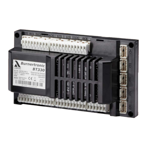
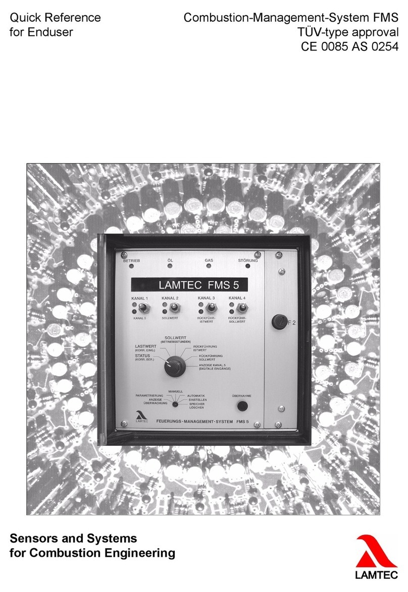
Lamtec CMS User manual

www.lamtec.de
Sensors and Systems for Combustion Engineering
Manual
Combustion Management System CMS


2
Table of Contents
Table of Contents
1 Important Information about the Manual . . . . . . . . . . . . . . . . . . . . . . . . . . . . . . . . . . . . . . . . 8
1.1 Validity of these Instructions. . . . . . . . . . . . . . . . . . . . . . . . . . . . . . . . . . . . . . . . . . . . . . . 8
1.2 References to Other Documents . . . . . . . . . . . . . . . . . . . . . . . . . . . . . . . . . . . . . . . . . . . 8
1.3 Standards, Directives and Approvals . . . . . . . . . . . . . . . . . . . . . . . . . . . . . . . . . . . . . . . . 8
1.4 Abbreviations . . . . . . . . . . . . . . . . . . . . . . . . . . . . . . . . . . . . . . . . . . . . . . . . . . . . . . . . . 10
2 Safety . . . . . . . . . . . . . . . . . . . . . . . . . . . . . . . . . . . . . . . . . . . . . . . . . . . . . . . . . . . . . . . . . . . 12
2.1 Classification of the Safety Instructions and Warnings . . . . . . . . . . . . . . . . . . . . . . . . . 12
2.2 Target Group . . . . . . . . . . . . . . . . . . . . . . . . . . . . . . . . . . . . . . . . . . . . . . . . . . . . . . . . . 13
2.3 Product-specific Dangers. . . . . . . . . . . . . . . . . . . . . . . . . . . . . . . . . . . . . . . . . . . . . . . . 13
2.3.1 Mounting Notes . . . . . . . . . . . . . . . . . . . . . . . . . . . . . . . . . . . . . . . . . . . . . . . . . 15
2.3.2 Installation Notes . . . . . . . . . . . . . . . . . . . . . . . . . . . . . . . . . . . . . . . . . . . . . . . . 16
2.3.3 Commissioning Notes . . . . . . . . . . . . . . . . . . . . . . . . . . . . . . . . . . . . . . . . . . . . 17
2.3.3.1 Electronic Ratio Control . . . . . . . . . . . . . . . . . . . . . . . . . . . . . . . . . . . . . . . . . . . 17
2.3.3.2 Basic Device . . . . . . . . . . . . . . . . . . . . . . . . . . . . . . . . . . . . . . . . . . . . . . . . . . . 18
2.3.3.3 Parameter Settings . . . . . . . . . . . . . . . . . . . . . . . . . . . . . . . . . . . . . . . . . . . . . . 18
2.3.3.4 FFS/ION/Terminal - Flame Tolerance Time . . . . . . . . . . . . . . . . . . . . . . . . . . . . 18
2.3.4 Electrical Connection Flame Sensor . . . . . . . . . . . . . . . . . . . . . . . . . . . . . . . . . 19
2.3.5 CO/O2Measuring Systems . . . . . . . . . . . . . . . . . . . . . . . . . . . . . . . . . . . . . . . . 20
2.3.6 Acceptance and Inspection . . . . . . . . . . . . . . . . . . . . . . . . . . . . . . . . . . . . . . . . 20
2.3.7 Components/Devices of External Manufacturers . . . . . . . . . . . . . . . . . . . . . . . 21
3 System Description . . . . . . . . . . . . . . . . . . . . . . . . . . . . . . . . . . . . . . . . . . . . . . . . . . . . . . . . 22
3.1 Brief Description. . . . . . . . . . . . . . . . . . . . . . . . . . . . . . . . . . . . . . . . . . . . . . . . . . . . . . . 22
3.2 Digital Input/Output Functions . . . . . . . . . . . . . . . . . . . . . . . . . . . . . . . . . . . . . . . . . . . . 24
3.2.1 Digital Inputs . . . . . . . . . . . . . . . . . . . . . . . . . . . . . . . . . . . . . . . . . . . . . . . . . . . 24
3.2.2 Digital Outputs . . . . . . . . . . . . . . . . . . . . . . . . . . . . . . . . . . . . . . . . . . . . . . . . . . 26
3.2.3 Assignment of Input/Output Functions. . . . . . . . . . . . . . . . . . . . . . . . . . . . . . . . 26
3.2.4 Chain Functions. . . . . . . . . . . . . . . . . . . . . . . . . . . . . . . . . . . . . . . . . . . . . . . . . 27
3.2.5 Curve Set Selection. . . . . . . . . . . . . . . . . . . . . . . . . . . . . . . . . . . . . . . . . . . . . . 27
3.3 Analogue Inputs/Outputs . . . . . . . . . . . . . . . . . . . . . . . . . . . . . . . . . . . . . . . . . . . . . . . . 27
3.3.1 Analogue Inputs. . . . . . . . . . . . . . . . . . . . . . . . . . . . . . . . . . . . . . . . . . . . . . . . . 27
3.3.2 Analogue outputs. . . . . . . . . . . . . . . . . . . . . . . . . . . . . . . . . . . . . . . . . . . . . . . . 27
3.4 Functional Description of the Modules. . . . . . . . . . . . . . . . . . . . . . . . . . . . . . . . . . . . . . 28
3.5 Life Cycle . . . . . . . . . . . . . . . . . . . . . . . . . . . . . . . . . . . . . . . . . . . . . . . . . . . . . . . . . . . . 29
4 CMS Components . . . . . . . . . . . . . . . . . . . . . . . . . . . . . . . . . . . . . . . . . . . . . . . . . . . . . . . . . 30
4.1 MCC – Master Control Component (burner module) . . . . . . . . . . . . . . . . . . . . . . . . . . . 30
4.1.1 For Your Safety . . . . . . . . . . . . . . . . . . . . . . . . . . . . . . . . . . . . . . . . . . . . . . . . . 30
4.1.2 Technical Data . . . . . . . . . . . . . . . . . . . . . . . . . . . . . . . . . . . . . . . . . . . . . . . . . . 30
4.1.3 Functional Description . . . . . . . . . . . . . . . . . . . . . . . . . . . . . . . . . . . . . . . . . . . . 32
4.1.4 LEDs . . . . . . . . . . . . . . . . . . . . . . . . . . . . . . . . . . . . . . . . . . . . . . . . . . . . . . . . . 32
4.1.5 Terminal Assignment . . . . . . . . . . . . . . . . . . . . . . . . . . . . . . . . . . . . . . . . . . . . . 34
4.1.6 Connection Diagram . . . . . . . . . . . . . . . . . . . . . . . . . . . . . . . . . . . . . . . . . . . . . 35
4.1.7 Interfaces. . . . . . . . . . . . . . . . . . . . . . . . . . . . . . . . . . . . . . . . . . . . . . . . . . . . . . 36
4.2 AEC-TPS – Actuator Extension Component Three-Point Step . . . . . . . . . . . . . . . . . . . 37
4.2.1 For Your Safety . . . . . . . . . . . . . . . . . . . . . . . . . . . . . . . . . . . . . . . . . . . . . . . . . 37
4.2.2 Technical Data . . . . . . . . . . . . . . . . . . . . . . . . . . . . . . . . . . . . . . . . . . . . . . . . . . 37
4.2.3 Functional Description . . . . . . . . . . . . . . . . . . . . . . . . . . . . . . . . . . . . . . . . . . . . 39

3
Table of Contents
4.2.4 LEDs . . . . . . . . . . . . . . . . . . . . . . . . . . . . . . . . . . . . . . . . . . . . . . . . . . . . . . . . . 40
4.2.5 Terminal Assignment . . . . . . . . . . . . . . . . . . . . . . . . . . . . . . . . . . . . . . . . . . . . . 41
4.2.6 Connection Diagram . . . . . . . . . . . . . . . . . . . . . . . . . . . . . . . . . . . . . . . . . . . . . 42
4.2.7 Interfaces. . . . . . . . . . . . . . . . . . . . . . . . . . . . . . . . . . . . . . . . . . . . . . . . . . . . . . 42
4.2.8 Approved Actuators . . . . . . . . . . . . . . . . . . . . . . . . . . . . . . . . . . . . . . . . . . . . . . 43
4.3 AEC-VS – Actuator Extension Component Variable Speed. . . . . . . . . . . . . . . . . . . . . . 43
4.3.1 For Your Safety . . . . . . . . . . . . . . . . . . . . . . . . . . . . . . . . . . . . . . . . . . . . . . . . . 43
4.3.2 Technical Data . . . . . . . . . . . . . . . . . . . . . . . . . . . . . . . . . . . . . . . . . . . . . . . . . . 44
4.3.3 Terminal Assignment . . . . . . . . . . . . . . . . . . . . . . . . . . . . . . . . . . . . . . . . . . . . . 47
4.3.4 Functional Description . . . . . . . . . . . . . . . . . . . . . . . . . . . . . . . . . . . . . . . . . . . . 48
4.3.5 LEDs . . . . . . . . . . . . . . . . . . . . . . . . . . . . . . . . . . . . . . . . . . . . . . . . . . . . . . . . . 48
4.3.6 Connection Diagram . . . . . . . . . . . . . . . . . . . . . . . . . . . . . . . . . . . . . . . . . . . . . 49
4.3.7 Interfaces. . . . . . . . . . . . . . . . . . . . . . . . . . . . . . . . . . . . . . . . . . . . . . . . . . . . . . 49
4.3.8 Sensors Suitable for CMS . . . . . . . . . . . . . . . . . . . . . . . . . . . . . . . . . . . . . . . . . 50
4.4 SDI - Safe Digital Input . . . . . . . . . . . . . . . . . . . . . . . . . . . . . . . . . . . . . . . . . . . . . . . . . 50
4.4.1 For Your Safety . . . . . . . . . . . . . . . . . . . . . . . . . . . . . . . . . . . . . . . . . . . . . . . . . 50
4.4.2 Technical Data . . . . . . . . . . . . . . . . . . . . . . . . . . . . . . . . . . . . . . . . . . . . . . . . . . 50
4.4.3 Terminal Assignment . . . . . . . . . . . . . . . . . . . . . . . . . . . . . . . . . . . . . . . . . . . . . 53
4.4.4 Functional Description . . . . . . . . . . . . . . . . . . . . . . . . . . . . . . . . . . . . . . . . . . . . 54
4.4.5 LEDs . . . . . . . . . . . . . . . . . . . . . . . . . . . . . . . . . . . . . . . . . . . . . . . . . . . . . . . . . 54
4.4.6 Connection Diagram . . . . . . . . . . . . . . . . . . . . . . . . . . . . . . . . . . . . . . . . . . . . . 55
4.4.7 Interfaces. . . . . . . . . . . . . . . . . . . . . . . . . . . . . . . . . . . . . . . . . . . . . . . . . . . . . . 55
4.5 SDO - Safe Digital Output . . . . . . . . . . . . . . . . . . . . . . . . . . . . . . . . . . . . . . . . . . . . . . . 56
4.5.1 For Your Safety . . . . . . . . . . . . . . . . . . . . . . . . . . . . . . . . . . . . . . . . . . . . . . . . . 56
4.5.2 Technical Data . . . . . . . . . . . . . . . . . . . . . . . . . . . . . . . . . . . . . . . . . . . . . . . . . . 56
4.5.3 Terminal Assignment . . . . . . . . . . . . . . . . . . . . . . . . . . . . . . . . . . . . . . . . . . . . . 59
4.5.4 Functional Description . . . . . . . . . . . . . . . . . . . . . . . . . . . . . . . . . . . . . . . . . . . . 59
4.5.5 LEDs . . . . . . . . . . . . . . . . . . . . . . . . . . . . . . . . . . . . . . . . . . . . . . . . . . . . . . . . . 60
4.5.6 Connection Diagram . . . . . . . . . . . . . . . . . . . . . . . . . . . . . . . . . . . . . . . . . . . . . 61
4.5.7 Interfaces. . . . . . . . . . . . . . . . . . . . . . . . . . . . . . . . . . . . . . . . . . . . . . . . . . . . . . 61
4.6 SAI - Safe Analogue Input . . . . . . . . . . . . . . . . . . . . . . . . . . . . . . . . . . . . . . . . . . . . . . . 62
4.6.1 For Your Safety . . . . . . . . . . . . . . . . . . . . . . . . . . . . . . . . . . . . . . . . . . . . . . . . . 62
4.6.2 Technical Data . . . . . . . . . . . . . . . . . . . . . . . . . . . . . . . . . . . . . . . . . . . . . . . . . . 62
4.6.3 Terminal Assignment . . . . . . . . . . . . . . . . . . . . . . . . . . . . . . . . . . . . . . . . . . . . . 64
4.6.4 Functional Description . . . . . . . . . . . . . . . . . . . . . . . . . . . . . . . . . . . . . . . . . . . . 64
4.6.5 LEDs . . . . . . . . . . . . . . . . . . . . . . . . . . . . . . . . . . . . . . . . . . . . . . . . . . . . . . . . . 65
4.6.6 Connection Diagram . . . . . . . . . . . . . . . . . . . . . . . . . . . . . . . . . . . . . . . . . . . . . 66
4.6.7 Interfaces. . . . . . . . . . . . . . . . . . . . . . . . . . . . . . . . . . . . . . . . . . . . . . . . . . . . . . 69
4.7 UI400 - User Interface . . . . . . . . . . . . . . . . . . . . . . . . . . . . . . . . . . . . . . . . . . . . . . . . . . 70
4.7.1 For Your Safety . . . . . . . . . . . . . . . . . . . . . . . . . . . . . . . . . . . . . . . . . . . . . . . . . 70
4.7.2 Technical Data . . . . . . . . . . . . . . . . . . . . . . . . . . . . . . . . . . . . . . . . . . . . . . . . . . 70
4.7.3 Functional Description . . . . . . . . . . . . . . . . . . . . . . . . . . . . . . . . . . . . . . . . . . . . 71
4.7.4 Pin Assignment . . . . . . . . . . . . . . . . . . . . . . . . . . . . . . . . . . . . . . . . . . . . . . . . . 71
4.7.5 Interfaces. . . . . . . . . . . . . . . . . . . . . . . . . . . . . . . . . . . . . . . . . . . . . . . . . . . . . . 72
4.8 Graphic User Interface - GUI607/GUI610/GUI615 . . . . . . . . . . . . . . . . . . . . . . . . . . . . 72
4.8.1 For Your Safety . . . . . . . . . . . . . . . . . . . . . . . . . . . . . . . . . . . . . . . . . . . . . . . . . 72
4.8.2 Technical Data . . . . . . . . . . . . . . . . . . . . . . . . . . . . . . . . . . . . . . . . . . . . . . . . . . 72
4.8.2.1 GUI607 . . . . . . . . . . . . . . . . . . . . . . . . . . . . . . . . . . . . . . . . . . . . . . . . . . . . . . . 72
4.8.2.2 GUI615 . . . . . . . . . . . . . . . . . . . . . . . . . . . . . . . . . . . . . . . . . . . . . . . . . . . . . . . 75

4
Table of Contents
4.8.3 Functional Description . . . . . . . . . . . . . . . . . . . . . . . . . . . . . . . . . . . . . . . . . . . . 77
4.8.4 Connection Diagram . . . . . . . . . . . . . . . . . . . . . . . . . . . . . . . . . . . . . . . . . . . . . 77
4.8.5 Interfaces. . . . . . . . . . . . . . . . . . . . . . . . . . . . . . . . . . . . . . . . . . . . . . . . . . . . . . 78
4.9 Router . . . . . . . . . . . . . . . . . . . . . . . . . . . . . . . . . . . . . . . . . . . . . . . . . . . . . . . . . . . . . . 79
4.9.1 For Your Safety . . . . . . . . . . . . . . . . . . . . . . . . . . . . . . . . . . . . . . . . . . . . . . . . . 79
4.9.2 Functional Description . . . . . . . . . . . . . . . . . . . . . . . . . . . . . . . . . . . . . . . . . . . . 79
5 Functional Description with Process Diagrams . . . . . . . . . . . . . . . . . . . . . . . . . . . . . . . . . 80
5.1 Basic Burner Sequencer Functionality. . . . . . . . . . . . . . . . . . . . . . . . . . . . . . . . . . . . . . 80
5.1.1 Default Process Flow for Gas Modulating with Pilot Burner . . . . . . . . . . . . . . . 80
5.1.2 Default Process Flow for Gas Modulating Without Pilot Burner . . . . . . . . . . . . 82
5.1.3 Default Process Flow for Oil Modulating With Pilot Burner . . . . . . . . . . . . . . . . 83
5.1.4 Default Process Flow for Oil Modulating Without Pilot Burner. . . . . . . . . . . . . . 85
5.2 Additional Burner Sequencer Functionality . . . . . . . . . . . . . . . . . . . . . . . . . . . . . . . . . . 86
5.2.1 Start Without Pre-Purge. . . . . . . . . . . . . . . . . . . . . . . . . . . . . . . . . . . . . . . . . . . 86
5.2.1.1 Requirements . . . . . . . . . . . . . . . . . . . . . . . . . . . . . . . . . . . . . . . . . . . . . . . . . . 86
5.2.1.2 Required Inputs/Outputs . . . . . . . . . . . . . . . . . . . . . . . . . . . . . . . . . . . . . . . . . . 86
5.2.1.3 Required Parameters. . . . . . . . . . . . . . . . . . . . . . . . . . . . . . . . . . . . . . . . . . . . . 86
5.2.1.4 Functional Description . . . . . . . . . . . . . . . . . . . . . . . . . . . . . . . . . . . . . . . . . . . . 86
5.2.2 Standby Mode . . . . . . . . . . . . . . . . . . . . . . . . . . . . . . . . . . . . . . . . . . . . . . . . . . 87
5.2.2.1 Requirements . . . . . . . . . . . . . . . . . . . . . . . . . . . . . . . . . . . . . . . . . . . . . . . . . . 87
5.2.2.2 Required Inputs/Outputs . . . . . . . . . . . . . . . . . . . . . . . . . . . . . . . . . . . . . . . . . . 87
5.2.2.3 Required Parameters. . . . . . . . . . . . . . . . . . . . . . . . . . . . . . . . . . . . . . . . . . . . . 87
5.2.2.4 Functional Description . . . . . . . . . . . . . . . . . . . . . . . . . . . . . . . . . . . . . . . . . . . . 88
5.2.3 Purging the Fuel Train . . . . . . . . . . . . . . . . . . . . . . . . . . . . . . . . . . . . . . . . . . . . 89
5.2.3.1 Requirements . . . . . . . . . . . . . . . . . . . . . . . . . . . . . . . . . . . . . . . . . . . . . . . . . . 89
5.2.3.2 Required Inputs/Outputs . . . . . . . . . . . . . . . . . . . . . . . . . . . . . . . . . . . . . . . . . . 89
5.2.3.3 Required Parameters. . . . . . . . . . . . . . . . . . . . . . . . . . . . . . . . . . . . . . . . . . . . . 89
5.2.3.4 Purging After Operation . . . . . . . . . . . . . . . . . . . . . . . . . . . . . . . . . . . . . . . . . . . 90
5.2.3.5 Purging with Digital Input . . . . . . . . . . . . . . . . . . . . . . . . . . . . . . . . . . . . . . . . . . 92
5.2.3.6 Purging Oil Gun during Standby Operation and Fuel Changeover by Pilot
Burner . . . . . . . . . . . . . . . . . . . . . . . . . . . . . . . . . . . . . . . . . . . . . . . . . . . . . . . . 93
5.2.3.7 Operating Modes for the 'Purging Fuel Train Function . . . . . . . . . . . . . . . . . . . 93
5.2.4 Pilot Burner - Continuous Operation . . . . . . . . . . . . . . . . . . . . . . . . . . . . . . . . . 93
5.2.4.1 Requirements . . . . . . . . . . . . . . . . . . . . . . . . . . . . . . . . . . . . . . . . . . . . . . . . . . 93
5.2.4.2 Required Inputs/Outputs . . . . . . . . . . . . . . . . . . . . . . . . . . . . . . . . . . . . . . . . . . 93
5.2.4.3 Required Parameters. . . . . . . . . . . . . . . . . . . . . . . . . . . . . . . . . . . . . . . . . . . . . 93
5.2.4.4 Process Sequence Chart: Pilot Burner Continuous Operation . . . . . . . . . . . . . 94
5.2.5 CPI/POC - Closed Position Indication/Proof of Closure . . . . . . . . . . . . . . . . . . 95
5.2.5.1 Requirements . . . . . . . . . . . . . . . . . . . . . . . . . . . . . . . . . . . . . . . . . . . . . . . . . . 95
5.2.5.2 Required Inputs/Outputs . . . . . . . . . . . . . . . . . . . . . . . . . . . . . . . . . . . . . . . . . . 95
5.2.5.3 Required Parameters. . . . . . . . . . . . . . . . . . . . . . . . . . . . . . . . . . . . . . . . . . . . . 95
5.2.5.4 Functional Description . . . . . . . . . . . . . . . . . . . . . . . . . . . . . . . . . . . . . . . . . . . . 95
5.2.6 Valve Leakage Test . . . . . . . . . . . . . . . . . . . . . . . . . . . . . . . . . . . . . . . . . . . . . . 95
5.2.6.1 Requirements . . . . . . . . . . . . . . . . . . . . . . . . . . . . . . . . . . . . . . . . . . . . . . . . . . 96
5.2.6.2 Required Parameters. . . . . . . . . . . . . . . . . . . . . . . . . . . . . . . . . . . . . . . . . . . . . 96
5.2.6.3 Functional Description . . . . . . . . . . . . . . . . . . . . . . . . . . . . . . . . . . . . . . . . . . . . 96
5.2.6.4 Valve Leakage Test Flow Chart . . . . . . . . . . . . . . . . . . . . . . . . . . . . . . . . . . . . . 97
5.2.6.5 Process Sequence Chart. . . . . . . . . . . . . . . . . . . . . . . . . . . . . . . . . . . . . . . . . . 98
5.2.6.6 Calculation Example . . . . . . . . . . . . . . . . . . . . . . . . . . . . . . . . . . . . . . . . . . . . . 98

5
Table of Contents
5.2.6.7 Suggested Circuit For Venting . . . . . . . . . . . . . . . . . . . . . . . . . . . . . . . . . . . . . 100
5.3 Electronic Ratio Control System . . . . . . . . . . . . . . . . . . . . . . . . . . . . . . . . . . . . . . . . . 101
5.3.1 Requirements . . . . . . . . . . . . . . . . . . . . . . . . . . . . . . . . . . . . . . . . . . . . . . . . . 101
5.3.2 Required Inputs/Outputs . . . . . . . . . . . . . . . . . . . . . . . . . . . . . . . . . . . . . . . . . 101
5.3.3 Required Parameters. . . . . . . . . . . . . . . . . . . . . . . . . . . . . . . . . . . . . . . . . . . . 101
5.3.4 Commissioning . . . . . . . . . . . . . . . . . . . . . . . . . . . . . . . . . . . . . . . . . . . . . . . . 101
5.3.5 Physical actuator types . . . . . . . . . . . . . . . . . . . . . . . . . . . . . . . . . . . . . . . . . . 101
5.3.5.1 Continuous Actuators. . . . . . . . . . . . . . . . . . . . . . . . . . . . . . . . . . . . . . . . . . . . 101
5.3.5.2 Actuators with TPS Control . . . . . . . . . . . . . . . . . . . . . . . . . . . . . . . . . . . . . . . 102
5.3.6 Logical Actuator Channels . . . . . . . . . . . . . . . . . . . . . . . . . . . . . . . . . . . . . . . . 102
5.4 Burner Firing Rate Controller . . . . . . . . . . . . . . . . . . . . . . . . . . . . . . . . . . . . . . . . . . . . 103
5.4.1 Requirements . . . . . . . . . . . . . . . . . . . . . . . . . . . . . . . . . . . . . . . . . . . . . . . . . 103
5.4.2 Required Inputs/Outputs . . . . . . . . . . . . . . . . . . . . . . . . . . . . . . . . . . . . . . . . . 103
5.4.3 Required Parameters. . . . . . . . . . . . . . . . . . . . . . . . . . . . . . . . . . . . . . . . . . . . 103
5.4.3.1 Configuration . . . . . . . . . . . . . . . . . . . . . . . . . . . . . . . . . . . . . . . . . . . . . . . . . . 103
5.4.3.2 I Term. . . . . . . . . . . . . . . . . . . . . . . . . . . . . . . . . . . . . . . . . . . . . . . . . . . . . . . . 104
5.4.3.3 Constant Controller . . . . . . . . . . . . . . . . . . . . . . . . . . . . . . . . . . . . . . . . . . . . . 104
5.4.3.4 Controlled by Atmospheric Conditions. . . . . . . . . . . . . . . . . . . . . . . . . . . . . . . 104
5.4.3.5 Limiting the Firing Rate Controller . . . . . . . . . . . . . . . . . . . . . . . . . . . . . . . . . . 105
5.4.3.6 Burner Shut-OFF . . . . . . . . . . . . . . . . . . . . . . . . . . . . . . . . . . . . . . . . . . . . . . . 106
5.4.4 Functional Description . . . . . . . . . . . . . . . . . . . . . . . . . . . . . . . . . . . . . . . . . . . 107
5.5 SPS Parameters . . . . . . . . . . . . . . . . . . . . . . . . . . . . . . . . . . . . . . . . . . . . . . . . . . . . . 107
6 Commissioning . . . . . . . . . . . . . . . . . . . . . . . . . . . . . . . . . . . . . . . . . . . . . . . . . . . . . . . . . . 108
6.1 Parameter and Password Input . . . . . . . . . . . . . . . . . . . . . . . . . . . . . . . . . . . . . . . . . . 108
6.2 Commissioning Tests . . . . . . . . . . . . . . . . . . . . . . . . . . . . . . . . . . . . . . . . . . . . . . . . . . 108
6.3 Programming of Curves . . . . . . . . . . . . . . . . . . . . . . . . . . . . . . . . . . . . . . . . . . . . . . . . 108
6.3.1 Programming Curves. . . . . . . . . . . . . . . . . . . . . . . . . . . . . . . . . . . . . . . . . . . . 109
6.3.2 Configuring Special Points. . . . . . . . . . . . . . . . . . . . . . . . . . . . . . . . . . . . . . . . 110
6.3.3 Configuring the Range Limits . . . . . . . . . . . . . . . . . . . . . . . . . . . . . . . . . . . . . 112
6.3.4 Shut-off Limits . . . . . . . . . . . . . . . . . . . . . . . . . . . . . . . . . . . . . . . . . . . . . . . . . 113
6.3.4.1 Run to Shut-off Limits . . . . . . . . . . . . . . . . . . . . . . . . . . . . . . . . . . . . . . . . . . . 113
6.3.4.2 Checking the Shut-OFF Limits of the CMS with the CMS Remote Software . 114
6.3.4.3 Checking the O2 Effect . . . . . . . . . . . . . . . . . . . . . . . . . . . . . . . . . . . . . . . . . . 115
7 Operating Control and Displays . . . . . . . . . . . . . . . . . . . . . . . . . . . . . . . . . . . . . . . . . . . . . 116
7.1 Operation, Controls and Display with UI400 . . . . . . . . . . . . . . . . . . . . . . . . . . . . . . . . 116
7.1.1 Menu Functions . . . . . . . . . . . . . . . . . . . . . . . . . . . . . . . . . . . . . . . . . . . . . . . . 116
7.1.2 Main Menu. . . . . . . . . . . . . . . . . . . . . . . . . . . . . . . . . . . . . . . . . . . . . . . . . . . . 118
7.1.3 Information Menu Path . . . . . . . . . . . . . . . . . . . . . . . . . . . . . . . . . . . . . . . . . . 118
7.1.3.1 Burner Details . . . . . . . . . . . . . . . . . . . . . . . . . . . . . . . . . . . . . . . . . . . . . . . . . 119
7.1.3.2 Recalling Fault History. . . . . . . . . . . . . . . . . . . . . . . . . . . . . . . . . . . . . . . . . . . 120
7.1.3.3 Software Version . . . . . . . . . . . . . . . . . . . . . . . . . . . . . . . . . . . . . . . . . . . . . . . 121
7.1.3.4 Display of Check Sums . . . . . . . . . . . . . . . . . . . . . . . . . . . . . . . . . . . . . . . . . . 122
7.1.3.5 Positions of Actuators . . . . . . . . . . . . . . . . . . . . . . . . . . . . . . . . . . . . . . . . . . . 122
7.1.3.6 Display IP Address. . . . . . . . . . . . . . . . . . . . . . . . . . . . . . . . . . . . . . . . . . . . . . 122
7.1.4 Manual Menu Path. . . . . . . . . . . . . . . . . . . . . . . . . . . . . . . . . . . . . . . . . . . . . . 123
7.1.5 Settings Menu Path . . . . . . . . . . . . . . . . . . . . . . . . . . . . . . . . . . . . . . . . . . . . . 124
7.1.5.1 Password. . . . . . . . . . . . . . . . . . . . . . . . . . . . . . . . . . . . . . . . . . . . . . . . . . . . . 124
7.1.5.2 Program Sequence . . . . . . . . . . . . . . . . . . . . . . . . . . . . . . . . . . . . . . . . . . . . . 125

6
Table of Contents
7.1.5.3 Configuring the Servomotors . . . . . . . . . . . . . . . . . . . . . . . . . . . . . . . . . . . . . . 128
7.1.5.4 Setting Curves . . . . . . . . . . . . . . . . . . . . . . . . . . . . . . . . . . . . . . . . . . . . . . . . . 129
7.1.5.5 Deleting Curves . . . . . . . . . . . . . . . . . . . . . . . . . . . . . . . . . . . . . . . . . . . . . . . . 130
7.1.5.6 Adjusting Controller . . . . . . . . . . . . . . . . . . . . . . . . . . . . . . . . . . . . . . . . . . . . . 131
7.1.5.7 Changing Password. . . . . . . . . . . . . . . . . . . . . . . . . . . . . . . . . . . . . . . . . . . . . 132
7.1.5.8 UI400 Settings . . . . . . . . . . . . . . . . . . . . . . . . . . . . . . . . . . . . . . . . . . . . . . . . . 132
7.2 Operation, Controls and Display with GUI607/610/615 . . . . . . . . . . . . . . . . . . . . . . . . 133
7.2.1 Process Diagram and Menu Navigation . . . . . . . . . . . . . . . . . . . . . . . . . . . . . 134
7.2.2 Password. . . . . . . . . . . . . . . . . . . . . . . . . . . . . . . . . . . . . . . . . . . . . . . . . . . . . 137
7.2.3 Burner Settings Menu . . . . . . . . . . . . . . . . . . . . . . . . . . . . . . . . . . . . . . . . . . . 138
7.2.4 Burner Firing-Rate Controller Menu. . . . . . . . . . . . . . . . . . . . . . . . . . . . . . . . . 148
7.2.5 CO/O2 Burner Optimisation Menu. . . . . . . . . . . . . . . . . . . . . . . . . . . . . . . . . . 152
7.2.6 Flame Monitoring System Menu . . . . . . . . . . . . . . . . . . . . . . . . . . . . . . . . . . . 154
7.2.7 System Functions Menu . . . . . . . . . . . . . . . . . . . . . . . . . . . . . . . . . . . . . . . . . 155
7.2.8 User Settings . . . . . . . . . . . . . . . . . . . . . . . . . . . . . . . . . . . . . . . . . . . . . . . . . . 162
7.3 Operation, Controls and Display with CMS Remote Software. . . . . . . . . . . . . . . . . . . 164
7.3.1 Remote Software . . . . . . . . . . . . . . . . . . . . . . . . . . . . . . . . . . . . . . . . . . . . . . . 164
7.3.1.1 Installation Prerequisites . . . . . . . . . . . . . . . . . . . . . . . . . . . . . . . . . . . . . . . . . 164
7.3.1.2 Installing the Software . . . . . . . . . . . . . . . . . . . . . . . . . . . . . . . . . . . . . . . . . . . 164
7.3.2 Offline/Online. . . . . . . . . . . . . . . . . . . . . . . . . . . . . . . . . . . . . . . . . . . . . . . . . . 167
7.3.2.1 Offline Mode . . . . . . . . . . . . . . . . . . . . . . . . . . . . . . . . . . . . . . . . . . . . . . . . . . 167
7.3.2.2 Online Mode . . . . . . . . . . . . . . . . . . . . . . . . . . . . . . . . . . . . . . . . . . . . . . . . . . 168
7.3.2.3 Connecting the CMS to the PC . . . . . . . . . . . . . . . . . . . . . . . . . . . . . . . . . . . . 168
7.3.3 CMS Remote Software User Interface . . . . . . . . . . . . . . . . . . . . . . . . . . . . . . 172
7.3.3.1 Dataset Menu . . . . . . . . . . . . . . . . . . . . . . . . . . . . . . . . . . . . . . . . . . . . . . . . . 173
7.3.3.2 Connection Menu. . . . . . . . . . . . . . . . . . . . . . . . . . . . . . . . . . . . . . . . . . . . . . . 176
7.3.3.3 Access Rights Menu . . . . . . . . . . . . . . . . . . . . . . . . . . . . . . . . . . . . . . . . . . . . 178
7.3.3.4 CMS Menu. . . . . . . . . . . . . . . . . . . . . . . . . . . . . . . . . . . . . . . . . . . . . . . . . . . . 180
7.3.3.5 Options Menu . . . . . . . . . . . . . . . . . . . . . . . . . . . . . . . . . . . . . . . . . . . . . . . . . 202
7.3.3.6 Help Menu . . . . . . . . . . . . . . . . . . . . . . . . . . . . . . . . . . . . . . . . . . . . . . . . . . . . 205
8 CO/O2Control. . . . . . . . . . . . . . . . . . . . . . . . . . . . . . . . . . . . . . . . . . . . . . . . . . . . . . . . . . . . 207
8.1 For Your Safety . . . . . . . . . . . . . . . . . . . . . . . . . . . . . . . . . . . . . . . . . . . . . . . . . . . . . . 207
8.2 Safety Concept . . . . . . . . . . . . . . . . . . . . . . . . . . . . . . . . . . . . . . . . . . . . . . . . . . . . . . 207
8.3 Requirements. . . . . . . . . . . . . . . . . . . . . . . . . . . . . . . . . . . . . . . . . . . . . . . . . . . . . . . . 208
8.4 Required Inputs/Outputs . . . . . . . . . . . . . . . . . . . . . . . . . . . . . . . . . . . . . . . . . . . . . . . 208
8.5 Required Parameters. . . . . . . . . . . . . . . . . . . . . . . . . . . . . . . . . . . . . . . . . . . . . . . . . . 208
8.6 Why Control CO?. . . . . . . . . . . . . . . . . . . . . . . . . . . . . . . . . . . . . . . . . . . . . . . . . . . . . 209
8.6.1 Where Can CO Control be Used? . . . . . . . . . . . . . . . . . . . . . . . . . . . . . . . . . . 209
8.6.2 Overview of Functions . . . . . . . . . . . . . . . . . . . . . . . . . . . . . . . . . . . . . . . . . . . 210
8.6.3 Optimisation Strategy . . . . . . . . . . . . . . . . . . . . . . . . . . . . . . . . . . . . . . . . . . . 211
8.6.4 Advantages of CO Control over O2Trim . . . . . . . . . . . . . . . . . . . . . . . . . . . . . 211
8.7 Operating Control and Displays . . . . . . . . . . . . . . . . . . . . . . . . . . . . . . . . . . . . . . . . . . 211
8.7.1 Is CO Control or O2 Trim Activated? . . . . . . . . . . . . . . . . . . . . . . . . . . . . . . . . 211
8.7.2 Display in the Case of Active CO/O2 Control . . . . . . . . . . . . . . . . . . . . . . . . . 213
8.7.2.1 Display with Active CO Control . . . . . . . . . . . . . . . . . . . . . . . . . . . . . . . . . . . . 213
8.7.2.2 Display for Active O2Trim . . . . . . . . . . . . . . . . . . . . . . . . . . . . . . . . . . . . . . . . 213
8.7.2.3 Status Display in Case of O2 Trim. . . . . . . . . . . . . . . . . . . . . . . . . . . . . . . . . . 213
8.7.2.4 Resetting Faults. . . . . . . . . . . . . . . . . . . . . . . . . . . . . . . . . . . . . . . . . . . . . . . . 214
8.8 Electrical Connection - Connection via LSB . . . . . . . . . . . . . . . . . . . . . . . . . . . . . . . . 214

7
Table of Contents
8.8.1 Electrical Connection . . . . . . . . . . . . . . . . . . . . . . . . . . . . . . . . . . . . . . . . . . . . 214
8.8.2 LAMTEC SYSTEM BUS (LSB) . . . . . . . . . . . . . . . . . . . . . . . . . . . . . . . . . . . . 214
8.9 Settings . . . . . . . . . . . . . . . . . . . . . . . . . . . . . . . . . . . . . . . . . . . . . . . . . . . . . . . . . . . . 215
8.9.1 Activating CO/O2 Control . . . . . . . . . . . . . . . . . . . . . . . . . . . . . . . . . . . . . . . . 215
8.9.2 Access Levels . . . . . . . . . . . . . . . . . . . . . . . . . . . . . . . . . . . . . . . . . . . . . . . . . 215
8.9.3 Password Entry . . . . . . . . . . . . . . . . . . . . . . . . . . . . . . . . . . . . . . . . . . . . . . . . 216
8.10 Installation and Commissioning . . . . . . . . . . . . . . . . . . . . . . . . . . . . . . . . . . . . . . . . . . 216
8.10.1 Guidelines for Commissioning CO/O2 Controller . . . . . . . . . . . . . . . . . . . . . . 216
8.10.2 Putting the Electronic Ratio Control System into Operation . . . . . . . . . . . . . . 217
8.10.3 Combined O2/CO/H2 Measurement LT3-F . . . . . . . . . . . . . . . . . . . . . . . . . . . 218
8.10.3.1 Checking the Connection from LT3-F to BT300 by LAMTEC SYSTEM BUS. 218
8.10.3.2 Operating and Comparing O2and COeMeasurements . . . . . . . . . . . . . . . . 219
8.10.4 Setting the CMS Correction Range . . . . . . . . . . . . . . . . . . . . . . . . . . . . . . . . . 219
8.10.5 CO Control: Start-up O2 Monitoring Shut-off Limits . . . . . . . . . . . . . . . . . . . . 222
8.10.6 Checking the Combustion-related Limit Values . . . . . . . . . . . . . . . . . . . . . . . . 223
8.10.7 Set and Optimise the CO Response Threshold on LT3-F . . . . . . . . . . . . . . . . 223
8.10.8 Commissioning the CO/O2 Control . . . . . . . . . . . . . . . . . . . . . . . . . . . . . . . . . 224
8.10.8.1 Commissioning with UI400 . . . . . . . . . . . . . . . . . . . . . . . . . . . . . . . . . . . . . . 224
8.10.8.2 Operating with PC Remote Software . . . . . . . . . . . . . . . . . . . . . . . . . . . . . . . 225
8.11 Monitoring Routines . . . . . . . . . . . . . . . . . . . . . . . . . . . . . . . . . . . . . . . . . . . . . . . . . . . 245
8.11.1 Dynamic Monitoring Routines . . . . . . . . . . . . . . . . . . . . . . . . . . . . . . . . . . . . . 245
8.11.2 CO/O2 Controller Information . . . . . . . . . . . . . . . . . . . . . . . . . . . . . . . . . . . . . 245
8.11.3 CO Controller Faults . . . . . . . . . . . . . . . . . . . . . . . . . . . . . . . . . . . . . . . . . . . . 246
8.11.4 O2 Trim Faults . . . . . . . . . . . . . . . . . . . . . . . . . . . . . . . . . . . . . . . . . . . . . . . . . 250
8.11.5 Burner Fault Shut-down when Falling below the Absolute O2 Minimum . . . . . 253
9 Faults. . . . . . . . . . . . . . . . . . . . . . . . . . . . . . . . . . . . . . . . . . . . . . . . . . . . . . . . . . . . . . . . . . . 254
10 Maintenance . . . . . . . . . . . . . . . . . . . . . . . . . . . . . . . . . . . . . . . . . . . . . . . . . . . . . . . . . . . . . 271
10.1 Firmware Update . . . . . . . . . . . . . . . . . . . . . . . . . . . . . . . . . . . . . . . . . . . . . . . . . . . . . 271
10.2 Maintenance Tasks . . . . . . . . . . . . . . . . . . . . . . . . . . . . . . . . . . . . . . . . . . . . . . . . . . . 278
10.3 Replacement Parts . . . . . . . . . . . . . . . . . . . . . . . . . . . . . . . . . . . . . . . . . . . . . . . . . . . 279
10.4 Customer Service Information . . . . . . . . . . . . . . . . . . . . . . . . . . . . . . . . . . . . . . . . . . . 279
11 Decommissioning . . . . . . . . . . . . . . . . . . . . . . . . . . . . . . . . . . . . . . . . . . . . . . . . . . . . . . . . 280
11.1 Important Notes on Shutdown/Return to Service. . . . . . . . . . . . . . . . . . . . . . . . . . . . . 280
11.2 Disposal Notes. . . . . . . . . . . . . . . . . . . . . . . . . . . . . . . . . . . . . . . . . . . . . . . . . . . . . . . 280
12 Appendix. . . . . . . . . . . . . . . . . . . . . . . . . . . . . . . . . . . . . . . . . . . . . . . . . . . . . . . . . . . . . . . . 281
12.1 CP Default Configuration . . . . . . . . . . . . . . . . . . . . . . . . . . . . . . . . . . . . . . . . . . . . . . . 281
12.2 Acceptance and Inspection . . . . . . . . . . . . . . . . . . . . . . . . . . . . . . . . . . . . . . . . . . . . . 281
12.3 Circuit Diagrams . . . . . . . . . . . . . . . . . . . . . . . . . . . . . . . . . . . . . . . . . . . . . . . . . . . . . 283
12.4 Accessories . . . . . . . . . . . . . . . . . . . . . . . . . . . . . . . . . . . . . . . . . . . . . . . . . . . . . . . . . 283
12.4.1 Power Supplies . . . . . . . . . . . . . . . . . . . . . . . . . . . . . . . . . . . . . . . . . . . . . . . . 283
12.4.2 Servo Drive . . . . . . . . . . . . . . . . . . . . . . . . . . . . . . . . . . . . . . . . . . . . . . . . . . . 284
12.5 EU Declaration of Conformity . . . . . . . . . . . . . . . . . . . . . . . . . . . . . . . . . . . . . . . . . . . 284
12.6 Display Symbols . . . . . . . . . . . . . . . . . . . . . . . . . . . . . . . . . . . . . . . . . . . . . . . . . . . . . 285
12.7 Indication Symbols. . . . . . . . . . . . . . . . . . . . . . . . . . . . . . . . . . . . . . . . . . . . . . . . . . . . 286

8
1 Important Information about the Manual
1.1 Validity of these Instructions
This manual is valid for the burner control system Combustion Management System CMS in
any configuration.
The information contained in this document refer to the software versions V1.0.3. If you use
any other software version as mentioned previously some of the described functions may not
be available or not all available functions work as described in this document.
1.2 References to Other Documents
Additional information is available for the CMS from the following documents:
• Parameter list (DLT7202): Lists and explains the relevant parameters
• Fault list (DLT7201): Lists potential faults and offers help and advice for remedying faults
• Description of the Modbus TCP protocol (DLT6104)
• Manual LT3-F with UI300 (DLT3140)
1.3 Standards, Directives and Approvals
The CMS complies with the following standards and directives:
Harmonised European standards:
USA and Canada:
The CMS can be used to control burners in accordance with:
The CMS can be used for combustion systems in accordance with:
EN 298: 2012-09
EN 12067-2: 2004-02 prEN 12067-2:2017
EN 13611: 2011-12
EN 60730-1: 2012-11
EN 60730-2-5:2011-02, parts 1–7
EN 60654-3:1996-08
EN 61508: 2011-02; parts 1–7
ISO 23552-1: 2007-10
UL 372 Edition 6
UL 1998 Edition 2
UL 840 Edition 3
UL 746C Edition 6
UL 60730-2-5
EN 676: 2008-11
EN 267: 2011-11
EN 50156

9
1 Important Information about the Manual
NOTICE
Respect the national safety regulations and standards.
EN 746-2
EN12952
EN12953
IEC 746-2
NFPA85
NFPA86

10
1 Important Information about the Manual
1.4 Abbreviations
A/D con-
verter
Analogue/Digital converter
AEC-ST Actuator Extension Component - Stopper Motor
AEC TPS Actuator Extension Component Three Point Step = module for DPS motors
with potentiometer feedback
AEC VS Actuator Extension Module Variable Speed = module for frequency inverters or
servo motors with 4 ... 20 mA interface
BS Burner sequencer
CMS Combustion Management System
CPI Closed Position Indication
DIN EN German Institute for Standardisation European Standard
DLTxxxx LAMTEC document number
EBM112 PROFINETmodule
ESD Electro Static Discharge
FI Frequency inverter
FFDT Flame failure detection time of the flame scanner
FFRT Flame failure response time = safety time during operation = sum of the param-
eter values of P 801 +P 816 + FFDT
GUI607 Graphical User Interface with 7" touch panel
GUI610 Graphical User Interface with 10" touch panel
GUI615 Graphical User Interface with 15" touch panel
HMI Human Machine Interface
IACS International Association of Classification Societies
ICOM Internal communication of the module
IDLE Open-circuit operation
iLSB Failsafe LAMTEC SYSTEM BUS
IO Input/Output
IP xx Protection class according to EN60529, xx = protection class code
LAN Local area network
LED Light emitting electrode
LSB LAMTEC System Bus
MCC Master Control Component = burner module
Middle-
ware
Software for data exchange between application programs working with differ-
ent operating systems or in heterogeneous networks.
MTBF Meantime between failure = average operating time between failures for repair-
able units
NTC Negative temperature coefficient
P xxx P = parameter, xxx = number of the parameter
PEC Programmable electronic component = Module of the CMS system
PLC Programmable logic control system

11
1 Important Information about the Manual
POC Proof of closure = A device that provides feedback that a plant part is in the
"Closed" position.
Pt100 Board measurement resistance (Ro= 100 Ohm) Ro= nominal resistance at 0 °C
Pt1000 Board measurement resistance (Ro= 1000 Ohm) Ro= nominal resistance at
0 °C
PWR Power
RAM Random-access memory
RECI Flue gas recirculation
Ri Internal resistance
RJ45 Connector Registered Jack (standard socket/plug) - Standard for Ethernet con-
necting cable
RL-L Lower range limits
RL-U Upper range limits
rpm Revolutions Per Minute
SAI Safe Analogue Inputs = module for failsafe analogue inputs
SDI Safe Digital Inputs = module for failsafe digital inputs
SDO Safe Digital Outputs = module for failsafe digital outputs
SELV Safe Extra Low Voltage = Voltage that does not exceed the limits for voltage
range I according to IEC 60449.
SIC Safety interlock chain
STL Safety temperature limiter
TFT Thin Film Transistor (Liquid Crystal Display, LCD technology)
TPS Three-point step
UI400 User interface = simple operating and display unit; display with symbols
VLT Valve leakage test
WLAN Wireless Local Area Network

12
2 Safety
2 Safety
2.1 Classification of the Safety Instructions and Warnings
The following symbols are used in this document to draw the user's attention to important safe-
ty information. They are located at points where the information is required. It is essential that
the safety information is observed and followed, and that applies particularly to the warnings.
DANGER!
This draws the user's attention to imminent danger. If it is not avoided, it will result in death or
very serious injury. The plant including its surroundings could be damaged.
WARNING!
This draws the user's attention to the possibility of imminent danger. If it is not avoided, it may
result in death or very serious injury. The plant including its surroundings could be damaged.
CAUTION!
This draws the user's attention to the possibility of imminent danger. If it is not avoided, it may
result in minor injuries. The plant including its surroundings could be damaged.
NOTICE
This draws the user's attention to important additional information about the system or system
components and offers further tips.
The safety information described above is incorporated into the instructions.
Thus, the operator is requested to:
1 Comply with the accident prevention regulations whenever work is being carried out.
2 Do everything possible within his control to prevent personal injury and damage to prop-
erty.

13
2 Safety
2.2 Target Group
These instructions must have been read carefully and completely before commencing with
any work. The basic prerequisite for working safely is compliance with all the specified safety
instructions.
NOTICE
All assembly, commissioning, troubleshooting and maintenance work may only be carried
out by authorised and trained personnel.
The device may be operated and maintained only by those who are capable of doing so
in terms of their level of knowledge and training.
For safety reasons, access to parameter settings must be restricted to authorised and
trained personnel.
2.3 Product-specific Dangers
Please observe the safety instructions to avoid personal injury and damage to property and
the environment!
CMS is a safety device! The device must not be opened, interfered with or modified. LAMTEC
assumes no liability for damages arising as a result of unauthorised interference!
• Qualified specialist staff are required to carry out all activities (assembly, installation, ser-
vicing, etc.).
• The person in charge will ensure that CMS base unit is compliant with protection class
IP40 or IP54 for outdoor use in accordance with DIN EN 60 529.
• Before working in the connection area, switch off the power supply to the plant from all
poles. Ensure that it cannot be switched back on and that the plant is voltage-free. There
is a risk of electric shock when the plant is not switched off.
• Adjustment of an open actuator must only be carried out by specialists who are trained in
mains voltage operation.
• To re-place or disconnect the plug connectors, all poles of the plant must be disconnected
from the mains. Check that there is no voltage!
• After each activity (e.g. assembly, installation, servicing, etc.) check wiring and parame-
ters to make sure it is in good working condition.
• If the equipment is dropped or suffers impact, you should no longer commission it. The
safety functions may also be impaired but fail to show any obvious external damage.
• These operating instructions describe many possible applications and functions and
should be used as guidelines. Carry out functional tests on the test bench and/or in the
plant application to ensure correct functioning and document the results.
• An electrical signal low or 0 V always corresponds to a logical 0 in the CMS and is evalu-
ated as inactive/safe state. If corresponding signals are connected to the CMS in a sys-
tem, it must be ensured that 0 is always the safe state.
• Condensation and humidity are to be avoided. If necessary, make sure that the installation
is sufficiently dry before you switch it on!
• Avoid static charge having a destructive effect in case of touching the device's electronic
components.

14
2 Safety
NOTICE
Recommendation: Use ESD equipment while working on electrics/electronics!
NOTICE
The optional ionisation monitoring system integrated into the MMC is suitable for continuous
operation.
• During the continuous fan stopping time (post-purging) following normal shutdown, the ex-
ternal safety mechanisms are not monitored. As a result, the combustion air fan cannot be
switched off by actuating one of the hazard switches included as part of the burner’s safety
interlock chain. Additional precautions such as a emergency stop button, or control panel
OFF switch, hard-wired to the combustion air fan control circuit should be considered as
the case may be.
• Access to the CMS and the network in which it is located may only be granted to author-
ised personnel.
The following optional measures must be guaranteed by the plant owner:
• Providing physical access protection to the system by:
Locking system
Alert system
Access protection to the electronics, e.g. lockable switch cabinet
• Providing technical access protection to the system by:
Password protection (restricting the group of people with access to passwords)
Firewall
• Respect IEC62443 regulations or comparable IT security standards.

15
2 Safety
2.3.1 Mounting Notes
• Observe national safety regulations, as well as guidelines given in national and interna-
tional standards.
• Safety extra low voltage (SELV) signal cables to and from the CMS must be physically
separated from line voltage/power cabling.
Frequency converter cables and switches or contactors that switch high, inductive or ca-
pacitive load are particularly relevant P.ex. spark igniter).
NOTICE
No parallel laying of control cables of solenoid valves, spark igniters, large servomotors or
similar devices.
Shielded cables from the field are connected directly, without using intermediate terminals. If
intermediate terminals are necessary, the shielding must be connected to an earth terminal
directly next to the terminal.
NOTICE
Avoid long distances without shielding!
• Only use the actuators with integrated feedback mentioned in the operating instructions.
Other actuators may only be used after consultation with LAMTEC and a supplementary
test.
• The connection between the actuators and the control valves must be positively connect-
ed throughout and designed for the maximum torque of the actuators.

16
2 Safety
2.3.2 Installation Notes
• Always lay the high-voltage ignition conductor separately and as far away as possible from
the device and the other conductors.
• Observe the relevant local and national regulations when wiring the electrical cables within
the burner.
• Tighten the screw terminals using a tightening torque >0.5Nm.
• Supply the feed cable with L, N and PE only. The N neutral conductor must not have po-
tential difference to the PE protective conductor.
• The pre-fuse on CMS is permitted to be max. 8 A fast-acting per output module (MCC and
output module).
• Ensure that strain relief of the connected conductors complies with relevant standards
(e.g. DIN EN 60730 and DIN EN 60 335).
• Ensure that no spliced strands can come into contact with any of the adjacent connec-
tions. Use suitable end splices.
• To replace or disconnect the plug-in connectors, all poles of the plant must be disconnect-
ed from the mains.
• The connection between the actuating drives and actuator devices for the fuel and com-
bustion air, as well as to any additional actuator devices that may be in use, must be pos-
itive locking.
• When wiring components with protective extra low voltage (SELV), and in connected de-
vices, make sure there is a safe separation to the mains voltage.
• Only connect passive or non-interacting devices to the CMS firing rate outputs (e.g. relay
without additional power supply). In the event of a fault, a supply of 230 V must be exclud-
ed to the CMS via these terminals.
• Use gold-plated silver contacts on 24 VDC inputs.
• To avoid faults on the LSB, the termination via P 1010 must be switched to active on the
first and last device connected to the bus.
• Via installation of the CMS modules, the flame sensor and all additional equipment, the
minimum protection class IP40 – or IP54 for use outdoors – must be ensured in accord-
ance with EN 60529.
• The analogue inputs connected to the modules must have the same potential as the pow-
er supply of the CMS system.

17
2 Safety
2.3.3 Commissioning Notes
• During commissioning it is essential to observe all safety accessory.
• There is no way to completely rule out the connection plugs being connected incorrectly.
For this reason, check the correct assignment of the plugs before commissioning the
plant.
• The person responsible for the plant/commissioning engineer must document the follow-
ing values after installing and commissioning a plant:
– Settings/changes to the parameters
– Setting values across the burner firing-rate range (e.g. curve progressions),
– corresponding exhaust gas values where applicable
– media pressure levels where applicable
You can partly use CMS Remote Software to print this data or alternatively keep a hand-
written note of it.
If tests are to be required by third parties in the application area of the device, these doc-
uments must be retained for presentation on request.
NOTICE
In CMS, parameter settings deviating from the application standards can be made.
The parameter settings must correspond to the relevant application standards as applica-
ble (e.g. EN 298, EN 676, EN 267, etc.) The documented evidence of conformity can be
managed via the LSB remote software.
NOTICE
Safety times can be called up via the HMIs UI400 and GUI607/GUI610/GUI615 and the CMS
Remote Software.
2.3.3.1 Electronic Ratio Control
• Guarantee proper operation by ensuring adequate excess air.
In order to do this, set the values for fuel and combustion air in such a way that
– combustion chamber pressure
– fuel pressure
– temperature and pressure of the combustion air
can ensure proper, stable operation through the entire range of burner firing rate until next
periodic inspection.
• Pay attention to wear and tear of actuators and actuator elements.
• Measure characteristic values of combustion process to document proper operation.

18
2 Safety
2.3.3.2 Basic Device
Check the following items prior to commissioning:
• Valves must be assigned correctly to valve outputs on CMS.
• Correct setting of time parameters (especially safety and pre-purge times).
• Flame sensor functioning well in case of:
• flame blow-off during operation (incl. flame-out response time)
• ambient light is present during pre-purge period
• at a missing flame formation while end of safety period starts
• Whether an ionisation or approved self-checking flame sensor is used as only these types
allow continuous operation.
• Functioning of flame sensor
– in case of flame blow-off during operation
– parasitic light being present during pre-purge period
– missing flame formation at the end of the safety-period
• Activated valve leakage control function for gas valves if required for application purposes.
– Ensure a correct leakage quantification.
2.3.3.3 Parameter Settings
Check the following:
• Correct setting of time parameters (especially safety and pre-purge periods).
• Activated valve leakage control function for gas valves if required for application purposes.
– If necessary, ensure the correct valve leakage quantification/monitoring time.
2.3.3.4 FFS/ION/Terminal - Flame Tolerance Time
The software processes the flame tolerance time*configurable in P801 and the pilot flame tol-
erance time** configurable in P816 in the same way.
To calculate the total response time in case of flame failure, the delay time of the related flame
scanner at terminal must be added. The following must be observed for each Flame sensor/
flame scanner:
• The overall time in accordance with the standard is from flame failure to safety shutdown
must be checked in the plant context.
• External flame scanner at terminal:
– Time starts as soon as the external digital input signal drops out.
– The time of the external flame scanner must also be taken into account.
• Internal flame scanner as an add on FFS or ION:
– Time starts with drop of the internally formed flame signal.
– The time of the sensor (FFS07/08) and the internal flame scanner (flame card) must
also be considered.
*Response time of the main flame at flame OFF
** Response time of the pilot flame at flame OFF

19
2 Safety
P801 and P816 describe the switch-off time of the digital, physical input to the digital, physical
output of the CMS. The system's safety time therefore depends on the sensor/scanner/ used
at the flame input.
The flame failure response time (FFRT) is the total of the parameter values and the flame de-
tection time of the sensor/scanner used.
2.3.4 Electrical Connection Flame Sensor
• CMS may only operate with appropriate approved flame sensors.
LAMTEC FFS07 and FFS08 sensors can be interfaced directly to the MCC or using an
F152 flame relay unit. Ionisation sensors may be interfaced using a LAMTEC F130i flame
relay. LAMTEC F200K and F300K flame sensors are also approved.
Alternatively, CMS can also be used with other flame detectors that are approved accord-
ing to DIN EN 298. In this case it must be noted that the switch-off times of the flame mon-
itor and the corresponding digital input are cumulative.
• If a flame monitor without continuous operation approval is connected, the continuous op-
eration approval for the entire system expires.
• In combustion systems with only one flame sensor, it must be ensured that the main flame
is always ignited at the pilot flame.
• Burners used in continuous operation must have dedicated flame monitors for pilot flame
and main flame.The main flame monitor may not respond to the flame of the pilot burner.
Interruptions and losses in signal transmission need to be minimised:
• Do not wire the sensor cable with other cables.
Flame signal is reduced through line capacities. Use a separate 7-pole cable.
• Consider the permitted length of sensor cables.
• The ionisation flame sensor supplied from the mains is not protected against contact. Pro-
tection against accidental contact is therefore obligatory.
• Ground the burner according to instructions – grounding the boiler itself is not sufficient!
• Position ignition electrode and ionisation flame sensor where spark cannot hit ionisation
flame sensor (risk of electrical overloading).
• The supply cable for connecting an ionisation electrode must have reinforced insulation in
accordance with DIN EN 60730-2-5 Section 20 to ensure protection against accidental
contact.
Used flame input Flame failure detection
time (FFDT)
Recommended parameter set-
ting for a flame failure response
time (FFRT) of 1 s (P801, P816)
Terminal Depending on the used
flame scanner (z.B: F300K)
0,2 s
FFS 07/08 500 ms 0,5 s
ION 800 ms 0,2 s
This manual suits for next models
10
Table of contents
Other Lamtec Control System manuals
Popular Control System manuals by other brands

Balboa Water Group
Balboa Water Group BP500 troubleshooting manual

DAVIS TECHNOLOGIES
DAVIS TECHNOLOGIES TC-3 Series instructions

GE
GE SPEEDTRONIC Mark V Troubleshooting Chart

dbx
dbx DriveRack PA Specifications

Beninca
Beninca VE.SOR operating instructions

INNOVATIVE POOL PRODUCTS
INNOVATIVE POOL PRODUCTS Smart Touch LE owner's manual