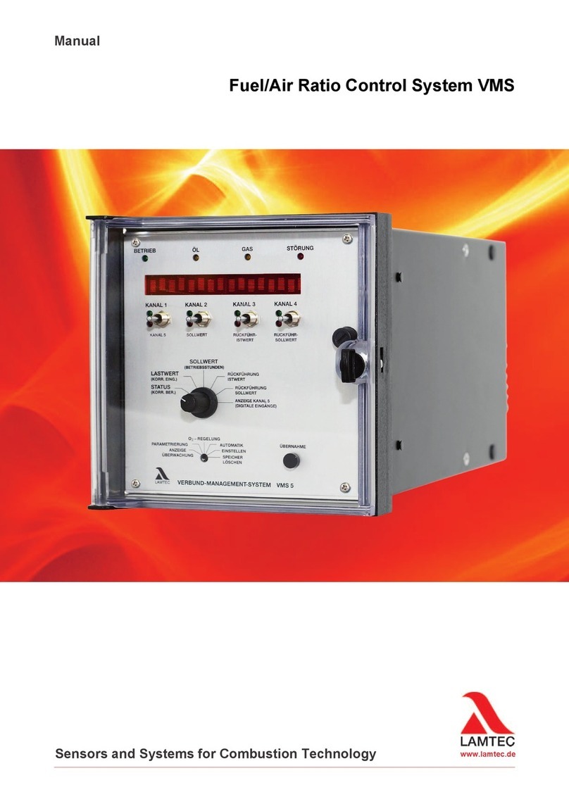
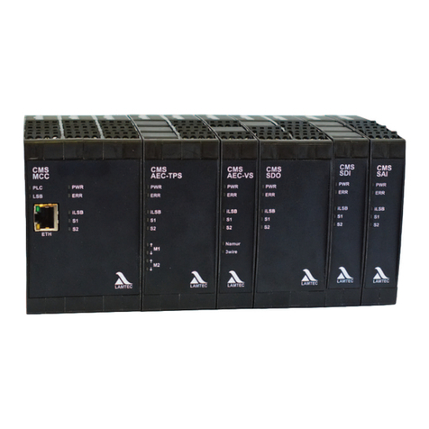
Lamtec FMS Series User manual

Quick Reference
for Enduser
Combustion-Management-System FMS
TÜV-type approval
CE 0085 AS 0254
Sensors and Systems
for Combustion Engineering


2
Inhaltsverzeichnis
Inhaltsverzeichnis
1 GENERAL INFOMATION . . . . . . . . . . . . . . . . . . . . . . . . . . . . . . . . . . . . . . . . .3
1.1 Validity of these instructions. . . . . . . . . . . . . . . . . . . . . . . . . . . . . . . . . . . . . . . . . . . . . . . . . . 3
1.2 For Your Safety . . . . . . . . . . . . . . . . . . . . . . . . . . . . . . . . . . . . . . . . . . . . . . . . . . . . . . . . . . . . . 4
1.3 Purpose . . . . . . . . . . . . . . . . . . . . . . . . . . . . . . . . . . . . . . . . . . . . . . . . . . . . . . . . . . . . . . . . . . . 6
2 COMISSIONING . . . . . . . . . . . . . . . . . . . . . . . . . . . . . . . . . . . . . . . . . . . . . . .10
2.1 O2-Regulation . . . . . . . . . . . . . . . . . . . . . . . . . . . . . . . . . . . . . . . . . . . . . . . . . . . . . . . . . . . . . 10
3 SYSTEM OPERATION . . . . . . . . . . . . . . . . . . . . . . . . . . . . . . . . . . . . . . . . . .11
3.1 Mode Display. . . . . . . . . . . . . . . . . . . . . . . . . . . . . . . . . . . . . . . . . . . . . . . . . . . . . . . . . . . . . . 11
3.2 4 Curve Sets FMS (Option) . . . . . . . . . . . . . . . . . . . . . . . . . . . . . . . . . . . . . . . . . . . . . . . . . .13
3.3 Check Sums - Running Time Meter . . . . . . . . . . . . . . . . . . . . . . . . . . . . . . . . . . . . . . . . . . . 13
3.4 Messages / Faults . . . . . . . . . . . . . . . . . . . . . . . . . . . . . . . . . . . . . . . . . . . . . . . . . . . . . . . . . . 14
3.5 FMS Fault Correction - Aids . . . . . . . . . . . . . . . . . . . . . . . . . . . . . . . . . . . . . . . . . . . . . . . . .26
3.6 Servicing . . . . . . . . . . . . . . . . . . . . . . . . . . . . . . . . . . . . . . . . . . . . . . . . . . . . . . . . . . . . . . . . . 44
3.6.1 Changing EPROMs . . . . . . . . . . . . . . . . . . . . . . . . . . . . . . . . . . . . . . . . . . . . . . . . . . . 44
3.6.2 Installing a New Software Version . . . . . . . . . . . . . . . . . . . . . . . . . . . . . . . . . . . . . . . . 45
4 APPENDIX. . . . . . . . . . . . . . . . . . . . . . . . . . . . . . . . . . . . . . . . . . . . . . . . . . . .47
4.1 Process Sequence Charts . . . . . . . . . . . . . . . . . . . . . . . . . . . . . . . . . . . . . . . . . . . . . . . . . . . 47
4.1.1 Gas Operation . . . . . . . . . . . . . . . . . . . . . . . . . . . . . . . . . . . . . . . . . . . . . . . . . . . . . . .47
4.1.2 Oil Operation . . . . . . . . . . . . . . . . . . . . . . . . . . . . . . . . . . . . . . . . . . . . . . . . . . . . . . . . 50
4.2 Connection Diagram Relay Modules . . . . . . . . . . . . . . . . . . . . . . . . . . . . . . . . . . . . . . . . . . 53
4.2.1 Connection Diagram Type 660 R 0016 . . . . . . . . . . . . . . . . . . . . . . . . . . . . . . . . . . . . 53
4.2.2 Block Diagram Type 660 R 0016 . . . . . . . . . . . . . . . . . . . . . . . . . . . . . . . . . . . . . . . . . 54
4.3 Wiring of the Analogue Inputs. . . . . . . . . . . . . . . . . . . . . . . . . . . . . . . . . . . . . . . . . . . . . . . . 55
4.4 Connecting Diagram FMS 4 / FMS 5 . . . . . . . . . . . . . . . . . . . . . . . . . . . . . . . . . . . . . . . . . . . 56
4.5 Technical Data . . . . . . . . . . . . . . . . . . . . . . . . . . . . . . . . . . . . . . . . . . . . . . . . . . . . . . . . . . . . 62
4.6 Accessories and Spare Parts . . . . . . . . . . . . . . . . . . . . . . . . . . . . . . . . . . . . . . . . . . . . . . . . 67
4.7 Declaration of Conformity . . . . . . . . . . . . . . . . . . . . . . . . . . . . . . . . . . . . . . . . . . . . . . . . . . . 70

3
1 General Infomation
1.1 Validity of these instructions
Standards The units conform to the following standards and regulations:
FMS:
EN 298
EN 230
EN 676 where applicable
EN 267where applicable
EN 12 953 - 7 u. 9 where applicable
EMC-Directive, Low Voltage Directive, Gas Appliance Directive
Integral leakage test:
Test mark:
EN 1643
gas side DIN DVGW PÜZ N6-2510 ASO 324
CE-0085 AS 0254

4
1 General Infomation
1.2 For Your Safety
In this operating instructions, the following symbols are used as important safety instructions
to the user. These symbols appear wherever there is a need for this information in a particular
section.
It is essential to note and comply with the safety instructions, particularly the warnings.
DANGER!
Indicates possible danger to personnel, particularly with regard to electrical equipment
WARNING!
Indicates possible danger to personnel if the system components are not handled correctly.
ATTENTION!
Indicates danger to system components or possible impairment of functionality.
TIP:
Contains important additional information for the user concerning the system or system com-
ponents and provides helpful tips
Contained in texts that provide information on how to perform tasks.
In performing all tasks, the operator is requested to observe all statutory safety regulations
and to do everything possible, according to the circumstances, to prevent injury to persons or
damage to equipment
The legislation on safety of appliances states:
Follow the instructions!
Proceed only in accordance with this FMS commissioning supplement (print no DLT 1015)
Use the equipment for the purpose described!
Operating by trained personnel only.
The appliance may only be operated and serviced by personnel with the required knowledge
and education to do so on the conditions and safety rules.
Follow the safety instructions of the burner manufacturer.
To be used in grounded power line network only.
If a flame monitor, which is not approved for continuous operation, is connected up, the ap-
proval for continuous operation of the system will be rendered invalid.
The unit is approved for use only with an external automatic flame guard. The automatic flame
guard type F 250 made by LAMTEC is used for testing purposes.
The following flame monitoring systems / flame sensors are applicable for use
(see the print no. of the associated documents in brackets behind the devices):
Compact flame detector F200 K1 and F200 K2(DLT 7620)
Flame monitoring system F150 (DLT 7521) and F250 (DLT 7540) in conjunction with the flame
sensors FFS05 / FFS05 Ex / FFS05 ExII (DLT 7501 and DLT 7503) und FFS06 (DLT 7502)

5
1 General Infomation
However, any other automatic flame guard tested in accordance with DIN EN 298 and/or DIN
EN 230 and approved for continuous operation may be used instead of this.
Before using a flame sensor / flame monitoring system you have to study the associated man-
ual. Pay attention to the specifications and observe the instructions.
Electrical connection to appliances not mentioned in these instructions Only after consultation
with the manufacturers or a qualified expert.If an automatic flame guard not approved for con-
tinuous operation is connected, approval of the system for continuous operation will lapse.Li-
ability for proper functioning of the appliance passes to the owner or operator. Liability for
correct functioning of the appliances in every case passes to the owner or operator, should the
appliance be incorrectly operated, serviced or repaired by persons without the requisite knowl-
edge, or if operation is inconsistent with the specified intended purpose.
In the event of modifications to the unit the type approval lapses. The unit's inputs and outputs
and associated modules must only be wired according to the specifications in these instruc-
tions.
LAMTEC GmbH & Co KG will not be liable for damage or injury arising out of a failure to ob-
serve the instructions above. The warranty and liability provisions of the terms and conditions
of sale and supply of LAMTEC GmbH & Co KG shall not be extended by virtue of the instruc-
tions above.
LAMTEC GmbH & Co KG will not be liable for damage or injury arising out of a failure to ob-
serve the instructions above. The warranty and liability provisions of the terms and conditions
of sale and supply of LAMTEC GmbH & Co KG shall not be extended by virtue of the instruc-
tions above.
Where reference is made to legislation, government regulations and standards, these are
based on the legal system of the Republic of Germany

6
1 General Infomation
1.3 Purpose
Purpose FMS 4 /
FMS 5
The FMS 4 / FMS 5 Combustion Management System is a control unit for FMS 4 / FMS 5 com-
bustion systems.
Brief description The FMS 4 adjusts up to four control elements as a function of a control variable (generally
the burner load) according to freely programmable curves.
The FMS 5 adjusts up to 5 control elements as a function of a control variable according to
freely programmable curves.
2 sets of curves (e.g. for oil or gas) can be filed as standard, with the option for 4 or 8 sets of
curves.
Examples of possible control elements:
– combustion air damper
– re-circulation fan
– combustion air fan
– flue gas damper
– fuel quantity
– flue gas fan
– atomiser steam
Up to 20 points can be programmed for each channel. The display is relative between 0 and
999.
The FMS has two correction inputs for shifting the setpoint curves, allowing a feedback control
(e.g. O2control unit to optimize combustion) to be connected up.
Each output is freely configurable, either three-point step control element output for direct ac-
tuation of a motor or constant output (on the FMS 5 the 5th channel is always constant). The
constant output can be set to any of the following variables:
– current signal 0 ... 20 mA
– current signal 4 ... 20 mA
– voltage signal 4 ... 20 mA
In the FMS 4 a so-called monitor output is integrated. Using the 4...20 mA signal with this out-
put, an internal value (such as the load position of the burner or position of the gas control
element) can be output.
The FMS has one serial interface for remote control/ display via PC (Windows software avail-
able separately) and for connection to other system components via BUS (e.g. fault message
system, O2control).
Connections for Profibus, Modbus, Ethernet, Interbus-S and CAN-BUS are available as op-
tions. Other BUS systems on request.

7
1 General Infomation
The FMS constantly monitors its own functions and these of the control elements connected.
Each analogue input (control variable and feedback or correction) is freely configurable via
plug-in cards.
Alternatively:
– potentiometer (1 - 5kΩ)
– step input (DPS)
– current signal 0/4 ... 20 mA
– Namur transmitter as a two-wire system
– inductive sensor with switch terminals in three-wire system
–PT100
The unit is of fail-safe construction.
The FMS contains a burner control unit with process control program.
Outputs:
– actuation of gas valves
– actuation of oil valves
– actuation of the ignition valve and ignition transformer
– fan release
– oil pre-heating
– fault signal
– signal outputs for oil and gas operation (in the off condition, oil operation is always indicat-
ed)
The external signals to the control unit are via floating contacts or chains of contacts.
The following signals can be pre-set:
– 3 separate safety interlock chains
– fault unlocking
– air pressure monitor
– gas pressure monitor (min.)
– flame signal (pilot flame monitor and ignition flame monitor)
– pre-ventilation and ignition release
– pre-ventilation suppression
– control release
– re-circulation release
– burner on
– fuel selection
This software option makes it possible to calculate the burner's required load setting continu-
ously for a specified target value (referred e.g. to temperature or pressure), through compari-
son with the actual value. This load setting can be notified internally to the electronic
compound as the specified value.
This software function makes it possible to regulate one or several actuators independently of
a switched-on O2actual value. By using a self-optimizing regulator strategy, it is also possible
to regulate burners with frequent load changes.

8
1 General Infomation
Purpose internal
firing rate
controller
This software option enables the calculating of the burner's required load setting continuously
for a specified setpoint value (referred e.g. to temperature or pressure), through comparison
with the actual value. This load setting can be notified internally to the electronic compound
as the specified value.
Purpose internal
O2-regulation
(option)
This software function makes it possible to regulate one or several actuators independently of
a switched-on O2actual value. By using a self-optimising regulator strategy, it is also possible
to regulate burners with frequent load changes.

9
1 General Infomation
Purpose of these
instructions
These instructions are concerned exclusively with commissioning and servicing.
Further information, for project planning examples, application, software settings etc., is given
in separate documents.
Special information dealing with optional equipment on this unit is explained in separate doc-
uments.
Conventions Sub-headings serve as a guide if you can already handle the FMS and merely want to refer
to certain information again.
Lines in italics after the sub-headings describe what the current state of the system should be.
If this is not the case, the subsequent operations will not show the desired result.
Lines in bold type indicate an action which you are to perform.
If you now follow the operations step by step, paying attention to the instructions, you will au-
tomatically be working correctly. If any of the reactions indicated do not occur, there is a fault
with the unit or the system. You should correct the fault first before proceeding
Correcting faults Follow the instructions identified by the numbers placed after the fault codes . You may find
the solution for your problem there.
This section, makes no claim to completeness. Should the actions described there have not
the desired effect, the unit or parts of the unit (e.g. front panel etc.) must be changed. If the
fault still occurs there may be a fault depending on the system.
TIP:
You can download the up-to-date version of these instructions from http://www.lamtec.de
as a PDF File
You will find the version no. of this document at the backside of this document in the document
number.
example:
DLT 1015-08-aD-0017
DLT 1015 = number of the document
aD = print version and language (English for this document)
0017 = version no. of the document
The figures and letters in brackets (1), (2), (3), (4), (5), (6), (7), (8), (A) and
(B) relate directly to the picture of the front panel. They identify the part on
which the specified action is to be performed or on which a reaction can be
seen.
The lines in ordinary typeface below the procedural instruction describe the
reaction of the system or unit following the operation.

10
2 Comissioning
2 Comissioning
2.1 O2-Regulation
Resetting od: Manually
Switch to "O2regulation” mode.
Press the Acceptance key and call up error text
Push key 3 (2) upwards →error deleted.
WARNING!
If deleting an error, the error text must always first be called up by pressing the "Enter" key.
Automatically:
During each new burner start-up
Calling up O2-
regulation text
messages
switch display to O2-Regulation
turn Selection switch (1) to „Status“,
push channel key 3 (4) upwards
Calling up the indication by pressing the „Enter“- key (3).
Back →press „Enter“- key again (3),
or turn selection switch (1) to another position.

11
3 System Operation
3 System Operation
3.1 Mode Display
Meaning of modes
on the FMS ON →"Switch-on sequence“
BE →"Ready"
ZÜ →"Ignition position"
EZ →"Setting/Ignition position"
GL →"Base load"
EG →"Setting/Base load"
NA →"Post-ventilation"
AU →"Off"
EI →"Setting"
SL →"Clear memory"
EV →"Setting/Pre-ventilation"
ES →"Setting/Control"
ST →"Fault"
VO →"Pre-ventilation"
HA or HAND →"Manual mode"
LE →"Load extern"
(RG) no display →"Control mode”
BE indicates that the signal is present on terminal 2, and all other signals = 0
If the FMS controls a flue gas damper, it opens. It is possible to switch to
"Setting”.
ZÜ
EZ
indicates that pre-ventilation is finished and the ignition position relay
pulls on. The FMS is in the ignition position, but the flame signal is
absent. Switching to "Setting” merely causes the mode display to switch
to EZ. Programming is not possible in this mode.
GL
EG
indicates that the burner is on (terminal 8=1), but the control release is
absent (terminal 4=0). The FMS therefore remains in base load position.
Switching to "Setting” merely causes the mode display to switch to EG.
Programming is not possible in this mode.
NA indicates that the FMS is in post-ventilation mode.
All signals = 0
All air channels open. When the configured time has elapsed, the FMS
changes to "AU” mode.
AU indicates that the FMS is "OFF”. All control elements closed.
Selector switch on "Automatic”, all signals = 0
EI indicates that the mode selector switch is on "Setting”. Single points can
now be altered or new curves can be entered.
SL indicates that the mode selector switch is set to "Clear memory”. By
pressing the "Enter" key the existing curve is cleared and a new curve
can be entered.

12
3 System Operation
O2-Regulator
modes
EV indicates that although the mode selector switch is on "Setting” it is nev-
ertheless performing the pre-ventilation routine. These is a signal on ter-
minal 3.
If the selector switch is on "Setting” and there is a "signal on terminal 3”,
nevertheless the FMS maintains its control function. The setting mode
(display "EI”) is only activated when the pre-ventilation is completed and
there is a flame signal and control release. Therefor the FMS can only be
programmed, when the signal combination corresponds either to the
"AU” and/or "BE” mode, or when the signal combination corresponds to
the "Automatic” mode.
ES indicates that although the mode selector switch is on "Setting”.
Iit's control function is working according to a calculated curve in the
RAM. The curve is calculated from a partial curve, which is already
entered. This mode is reached if the burner is switched off and is
restarted during a programming sequence. The programming can be
continued by operating a switch (change to "EI” mode”). Flame signal
and control release are present.
ST indicates that the FMS is set to "Fault”. The fault code can be called up in
switch position "Status”. In the switch position "load rating” the load rat-
ing at the time when the fault occurs, is displayed.
VO indicates that the FMS is in "Pre-ventilation” mode. There is a signal on
terminal 2 and a signal on terminal 3. Pre-ventilation routine is active.
HAND
or
HA
indicates that the FMS has been switched to manual mode whilst the
burner is running. In the selector switch position "Load rating” the load
can be adjusted by actuating the channel 1 switch. To quit manual mode,
actuate any switch but the channel 1 switch.
ext.Hand indicates that the FMS was switched to manual operation, but the load
was specified externally and not via the channel 1 key (that is, e.g. via
remote software or bus).
LE indicates that the output regulator of the FMS is deactivated and the fir-
ing rate is controlled by an external signal
Input Terminals Mode
term.2 term.3 term.4 term.8 If also on "Setting"
0 0 0 0 EI or EZ
1 0 0 0 AU or NA EV
1100VO
1001GL EG
1011Automatic EI
op O2-regulator on standby (at startup burner), or O2-regulator temporarily switched off
as a function of load via parameters 914 and 915.
or O2-regulator active
ot O2-regulator temporarily deactivated (air shortage, probe dynamics, etc)
od O2-regulator deactivated (during fault) e.g. test routines failed during burner startup,
dynamic test negative, O2-regulator temporarily deactivated for longer than 1 hour,
etc.

13
3 System Operation
3.2 4 Curve Sets FMS (Option)
The FMS offers the optional facility for using 4 curve sets. In this case 2 curve sets are firmly
assigned to oil operation and 2 curve sets to gas operation. The curve sets are then selected
via terminal 75 (fuel selection) and additionally via the fuel safety interlock circuits.
* SIC = Safety Interlock Chain
Since the fuel safety interlock circuits now serve here for selection of the curve set, they are,
contrary to the standard flowchart, monitored immediately after starting (or more precisely af-
ter the end of t1, see flow charts) and must remain on until burner-shut-of.
3.3 Check Sums - Running Time Meter
Recalling the
Checksum and the
safety times
Selector switch (1) to "Set-point feedback"
Press "Enter" (3) and keep pressed
- the checksum and the safety times appear one after the other on the display
Each of the parameter levels is safeguarded by its own checksum. The checksum for each
level and the safety and pre-ventilation times are displayed here in succession.
Order:
1st oil safety time in seconds
2nd oil safety time in seconds
1st gas safety time in seconds
2nd gas safety time in seconds
Pre-ventilation time in seconds
On the FMS without pilot burner the statement of the 2nd safety time contains safety time. The
statement of the 1st safety time is then irrelevant.
TIP:
If the parameter has been changed, the checksum will change , too, if a total reboot has been
proceeded or the duration of 1h has passed.
Fuel Selection
Terminal 75
SIC * Oil
Terminal 69
SIC * Gas
Terminal 5
Curve Set
0 1 0 Curve set 1 (oil op.)
0 0 1 Curve set 2 (gas op.)
1 1 0 Curve set 3 (oil op.)
1 0 1 Curve set 4 (gas op.)
X 0 0 FMS does not start on fault during
operation.
X 1 1 FMS does not start on fault during
operation
CRC 16 level 0: adjustable without password
1: adjustable by person commissioning
2: adjustable by the burner manufactorer or the boiler manufactorer
3: adjustable by LAMTEC only
4: adjustable by LAMTEC only

14
3 System Operation
Calling up
running time meter
TIP:
The sum of the curve set 1 running hours and curve set 2 running hours does not necessarily
give the running hours value displayed in total. The total counter relates to the FMS running
hours. It runs as soon as the unit is connected to a voltage (this also provides the basis for the
fault history).
The single running time meters relate to the burner running hours. These run as soon as the
burner is in operation with the respective curve set (flame signal to the FMS).
3.4 Messages / Faults
TIP:
If the processor detects a fault, it runs the outputs in the programmed direction, of FMS fault
e.g. air on, fuel off, re-circulation closed The fuel solenoid valves close. The fault signal relay
pulls on with a few seconds delay. Automatic restarting may be possible, depending on the
nature of the fault
Reading the faults Red fault LED lights up
Selector switch to "Status”
- Fault code is displayed
Note code
Press Enter
- Plain text message appears on display incl. running time meter reading up to the time of the
fault
Selector switch on "Load rating“
- Load rating at the time of the fault is displayed (externally and internally)
Note load ratings
Fault reset Selector switch to "Status”
Left-hand switch up
- the fault is cleared unless the cause is still directly present.
Selector switch (1) to set-point
Press "Enter" (3) and keep pressed
– a moving text appears giving the following data:
– total running hours
– running hours on curve set 1
– starts on curve set 1
– running hours on curve set 2
– starts on curve set 2
Where the 4 curve set or 8 curve set option is used the running hours and
starts on the additional curve sets are also displayed.

15
3 System Operation
Alternative:
Calling up fault
history
The FMS stores the last 10 faults with the associated running time meter.
TIP:
If you are sure that there has been a voltage on the FMS at all times since the last fault, the
time of the fault can be determined by means of the current running time meter reading and
the current time.
FMS: Set signal on terminal 3 briefly (min. 2 seconds) via external switch.
Fault is cleared!
Selector switch (1) to Status
- current status appears on display
Channel 1 switch (4) up
- last fault code appears on display and the load values of the moment,
when the fault occurs, are displayed.
Press "Enter" (3)
- text and running time meter value are displayed
Channel 1 switch (4) up again
- penultimate fault code appears on display and the load values of the
moment, when the fault occurs, are displayed.
In this way the fault history can be browsed by operating the channel 1
switch

16
3 System Operation
O2- regulation
perturbed
Air shortage
perturbation
If the actual O2value is significantly smaller than the target value and corrective action by the
FMS/VMS cannot rectify this error, the regulator is deactivated and the base value for air
shortage errors is output. If desired, an air shortage burner shut-down can be triggered by the
FMS/VMS. This is achieved by setting parameter 897 to 1.
The error code is H360, "Error shut-down by O2regulator”.
Resetting O2-errors O2errors are automatically reset with each new burner start-up. This is permissible, since a
100% O2measurement test is performed at each start-up.
Manual resetting of O2errors is possible at any time, as follows:
Set selector switch (1) to Status
-FMS in O2regulation mode?
If not, switch over to O2regulation mode by pushing channel key 3 (4) upwards
Press the "Enter" key (3) and
-call up the cause of error (mandatory!)
Push key 3 (4) upwards
Calling up O2-
regulation fault
history
Switch over to FMS/VMS mode (compound regulator)
Selector switch (1) to Status
Switch channel 3 down
- In this way the fault history can be browsed through by actuating the switch channel 2
In the event of perturbations, a warning message is displayed and the O2
regulator is deactivated. The specified base value "Without regulation” or
the one for "Air shortage” is set.
The display shows the running text "O2regulation perturbed”.
The burner is not shut down as a rule.
The corresponding error code can be called up by setting the selector
switch to Status. A plain text message about the cause of error appears
after pressing the "Enter" key (3).

17
3 System Operation
Calling up fault
history
TIP:
If you are sure that there has been a voltage on the FMS at all times since the last fault, the
time of the fault can be determined by means of the current running time meter reading and
the current time.
The display of O2history disappears automatically after 5 sec. O2regulator
faults lasting over 30 sec. are stored. They are only stored in the EEPROM,
once the fault is cleared up or the FMS leaves the operating mode "Regula-
tion" or Base Load".
The FMS stores the last 10 faults with the associated running time meter
values
Selector switch (1) to Status
- Instantaneous status appears on display
Channel 1 switch (4) up
- last fault code appears on display
- associated running time meter reading appears on display
Press Acceptance (3)
- text and running time meter reading appears on display
Channel 1 switch (4) up again
- penultimate fault code appears on display
- associated running time meter reading appears on display
In this way the fault history can be browsed through by operating the
channel 1 switch

18
3 System Operation
Fault Codes An "H" before the fault code indicates that the main processor has identified the cause of the
defect.
A preceding “Ü” indicates that the monitoring processor has triggered the fault.
An * signifies that re-starting is permitted for this fault.
A blinking Fault-LED means, that a autonomic restart will happen.
** it means, that it tries as many as possible the burner start.
Fault Code Number
Aids FMS Aids ETA
0 No fault code available for this fault
1 No pilot flame appearing
2 Light/dark check failure
3 Flame fault during ignition H2
4 ** Flame fault during operation
5 Flame signal does not appear during 1st safety time H2
6 Flame signal goes out during stabilising time. H2
7 Flame signal goes out during 1st safety time H2
8 Flame signal goes out during 2nd safety time H2
9 Flame signal does not appear during safety time H2
10 Flame signal goes out immediately after ignition H2
11 Internal fault: 5 sec. outside light monitoring period not kept
12 Relay module not connected or missing 24V supply for relay
13 Main flame signal appears during ignition
102 Internal fault: Internal communication FIFO has overflowed A7
103 Internal fault: Error in misc. data A7,A9
104 Internal fault: D/A converter faulty A7
105 * Curve data faulty! Curve set no.: A7,A13,
A9
106 parameters not equal for parameter no.: A7,A14,
A9
107 Invalid configuration A7,A12
108 Different input signals on main processor and monitoring processor. A7,G8
110 CRC-16 test has found an error A7,A11
111 RAM test detecting error A7
112 ETAMATIC self-test exceeds time-out limit
120* Different operating modes for mon. and main processor A24
121 Correction is outside permissible range. Channel: 1 F1
122 Correction is outside permissible range. Channel: 2 F1
123 Correction is outside permissible range. Channel: 3 F1
124 Correction is outside permissible range. Channel: 4 F1
125 Correction is outside permissible range. Channel: 5 F1
139 Integr. Flame Detector: self-test fault
140 EEPROM is faulty. A2, A7,
A12, A15

19
3 System Operation
141 Potentiometer faulty, feedback changing too quickly: channel 1 E13
142 Potentiometer faulty, feedback changing too quickly: channel 2 E13
143 Potentiometer faulty, feedback changing too quickly: channel 3 E13
144 Potentiometer faulty, feedback changing too quickly: channel 4 E13
145 Potentiometer faulty, feedback changing too quickly: channel 5 E13
151** Recirculation damper deactivated, out of time in reaching CLOSED position,
channel: 1 E2,B1,B3
152** Recirculation damper deactivated, out of time in reaching CLOSED position,
channel: 2 E2,B1,B3
153** Recirculation damper deactivated, out of time in reaching CLOSED position,
channel: 3 E2,B1,B3
154** Recirculation damper deactivated, out of time in reaching CLOSED position,
channel: 4
E2,B1,B3
155** Recirculation damper deactivated, out of time in reaching CLOSED position,
channel: 5
E2,B1,B3
161** Monitoring direction of rotation: channel 1 E2,E17
162** Monitoring direction of rotation: channel 2 E2,E17
163** Monitoring direction of rotation: channel 3 E2,E17
164** Monitoring direction of rotation: channel 4 E2,E17
165** Monitoring direction of rotation: channel 5 E2,E17
171** Dead band over range too long: channel 1 B1,B4,E2,
E4,E5
172** Dead band over range too long: channel 2 B1,B4,E2,
E4,E5
173** Dead band over range too long: channel 3 B1,B4,E2,
E4,E5
174** Dead band over range too long: channel 4 B1,B4,E2,
E4,E5
175** Dead band over range too long: channel 5 B1,B4,E2,
E4,E5
181** Dead band under range too long: channel 1 B1,B4,E2,
E4,E5
182** Dead band under range too long: channel 2 B1,B4,E2,
E4,E5
183** Dead band under range too long: channel 3 B1,B4,E2,
E4,E5
184** Dead band under range too long: channel 4 B1,B4,E2,
E4,E5
185** Dead band under range too long: channel 5 B1,B4,E2,
E4,E5
191* 1st monitoring band over range too long: channel 1 B1,B3
192* 1st monitoring band over range too long: channel 2 B1,B3
193* 1st monitoring band over range too long: channel 3 B1,B3
194* 1st monitoring band over range too long: channel 4 B1,B3
195* 1st monitoring band over range too long: channel 5 B1,B3
Aids FMS Aids ETA
Other manuals for FMS Series
1
This manual suits for next models
2
Table of contents
Other Lamtec Control System manuals
Popular Control System manuals by other brands

Balboa Water Group
Balboa Water Group BP500 troubleshooting manual

DAVIS TECHNOLOGIES
DAVIS TECHNOLOGIES TC-3 Series instructions

GE
GE SPEEDTRONIC Mark V Troubleshooting Chart

dbx
dbx DriveRack PA Specifications

Beninca
Beninca VE.SOR operating instructions

INNOVATIVE POOL PRODUCTS
INNOVATIVE POOL PRODUCTS Smart Touch LE owner's manual