Landi Renzo A1 V05 Guide

MANUALE INSTALLAZIONE E REGOLAZIONE
pag. 6
INSTALLATION AND ADJUSTMENT MANUAL
page 13
MANUEL INSTALLATION ET REGLAGE
page 20
GUIA INSTALLACION Y REGULACION
pag. 27
LAMBDA CONTROL SYSTEM A1 V05
LPG & CNG CONVERSION SYSTEMS FOR VEHICLES
LANDI RENZO S. p. A. - Via F.lli Cervi, 75/2 - 42100 Reggio Emilia - Italy
Tel. +39 / 05 22 38 26 78 - Fax +39 / 05 22 38 29 06
190159440/1

LANDI RENZO S.p.A.
LAMBDA CONTROL SYSTEM A1 V05
2 / 33
I
Schema Tecnico Gpl
GB
Lpg Technical Drawing
F
Schéma Technique Gpl
E
Esquema Técnico Glp
Fig. 1

LANDI RENZO S.p.A.
LAMBDA CONTROL SYSTEM A1 V05
3 / 33
I
Schema Tecnico Metano
GB
Cng Technical Drawing
F
Schéma Technique Gnc
E
Esquema Técnico Gnc
Fig. 2

LANDI RENZO S.p.A.
LAMBDA CONTROL SYSTEM A1 V05
4 / 33
I
Schemi Tecnici
GB
Technical Drawings
F
Schémas Techniques
E
Esquemas Técnicos
V05V05
LAMBDA CONTROLLAMBDA CONTROL
SYSTEM A/1SYSTEM A/1
ITALY
LANDI RENZO S.p.a.LANDI RENZO S.p.a.
LCS AG DGM 48522 GPL DEL 24-1-94LCS AG DGM 48522 GPL DEL 24-1-94
LCS AM DGM 48523 GM DEL 24-1-94LCS AM DGM 48523 GM DEL 24-1-94
V05V 05
LAMBDA CONTROLLAMBDA CONTROL
SYSTEM A/1SYSTEM A/1
ITALY
LANDI RENZO S.p.a.LANDI RENZO S.p.a.
LCS AG DGM 48522 GPL DEL 24-1-94LCS AG DGM 48522 GPL DEL 24-1-94
LCS AM DGM 48523 GM DEL 24-1-94LCS AM DGM 48523 GM DEL 24-1-94
Fig. 3 Fig. 4
Fig. 5
Fig. 6

LANDI RENZO S.p.A.
LAMBDA CONTROL SYSTEM A1 V05
5 / 33
I
Schemi Tecnici
GB
Technical Drawings
F
Schémas Techniques
E
Esquemas Técnicos
123
+12 V
-
+ 5 V
-
Segnale TPS
TPS signal
Signal TPS
Señal TPS
Segnale TPS
TPS signal
Signal TPS
Señal TPS
AB
Fig. 7
Fig. 8
Fig. 9

LANDI RENZO S.p.A.
MANUALE INSTALLAZIONE E REGOLAZIONE LAMBDA CONTROL SYSTEM A1 V05
6 / 33
I
Legenda
LAMBDA CONTROL SYSTEM A1 V05 è un
sistema elettronico autoregistrante per la gestione
dell'alimentazione a gas ( Gpl o Metano) di veicoli
dotati di sonda lambda e marmitta catalitica: non
richiede regolazioni manuali ed ha la capacità di
adattarsi automaticamente alle differenti condizioni
ambientali e di utilizzo dei veicoli, assicurando una
carburazione ottimale in termini di guidabilità,
consumi ed emissioni.
LEGENDA (Fig. 1 Gpl; Fig. 2 Metano)
Il sistema è costituito dai seguenti elementi:
A) Computer LCS A1 V05
B) Attuatore Elettromeccanico Lineare
C) Commutatore/indicatore LCS A1 V05
D) Cablaggi per il collegamento del Computer
LCS A1 V05 ai relativi dispositivi
E) Connettore per programmazione e diagnosi
Gli altri elementi rappresentati nello schema sono i
seguenti:
F) Tester Programmatore V05
G) Personal Computer con Kit Interfaccia V05 (in
alternativa al Tester Programmatore V05)
H) TPS (Sensore posizione farfalla)
I) Iniettori benzina
L) Sonda Lambda
M) Bobina di accensione
N) Batteria
O) Elettrovalvola gas
P) Riduttore di pressione
Q) Sensore livello gas
Gli schemi rappresentati in Fig. 1 e 2
relativamente all’impianto Gpl e Metano sono
generici; per le specifiche riguardanti i
collegamenti elettrici, vedere il paragrafo 6.
Specifiche Tecniche
1. SPECIFICHE TECNICHE
1.1 COMPUTER LCS A1 V05
•
Caratteristiche elettriche
- Tensione di lavoro:
12V (-20% / +30%)
- Corrente massima assorbita durante il
funzionamento:
0,6A
- Corrente massima applicabile al relè per interru-
zione iniezione benzina (fili gialli):
6,5A
- Corrente massima erogabile per dispositivi di
controllo gas (fili blu):
6,5A
- Grado di protezione da polvere ed acqua:
IP65
•
Funzioni programmabili
- Numero cilindri / tipo accensione
- Tipo segnale giri motore
- Tipo commutazione automatica benzina/gas
- Numero giri per commutazione automatica
- Tempo sovrapposizione carburanti durante com-
mutazione automatica
- Tipo TPS (sensore di posizione farfalla)
- Tipo sensore livello gas
- Tipo sonda lambda
- Ritardo lettura sonda lambda
- Tipo emulazione sonda lambda
- Opzione massima apertura farfalla in fase di
accelerazione
- Minima / massima apertura attuatore
- Opzione cut-off
- Opzione default fisso
- Reset memoria
1.2 ATTUATORE ELETTROMECCANICO
LINEARE
•
Caratteristiche elettriche
- Tensione di lavoro:
12V
- Corrente assorbita:
150mA
- Potenza nominale:
2W
- Temperatura di funzionamento:
-20°C / +120°C
- Grado di protezione da polvere ed acqua:
IP65

LANDI RENZO S.p.A.
MANUALE INSTALLAZIONE E REGOLAZIONE LAMBDA CONTROL SYSTEM A1 V05
7 / 33
Funzioni
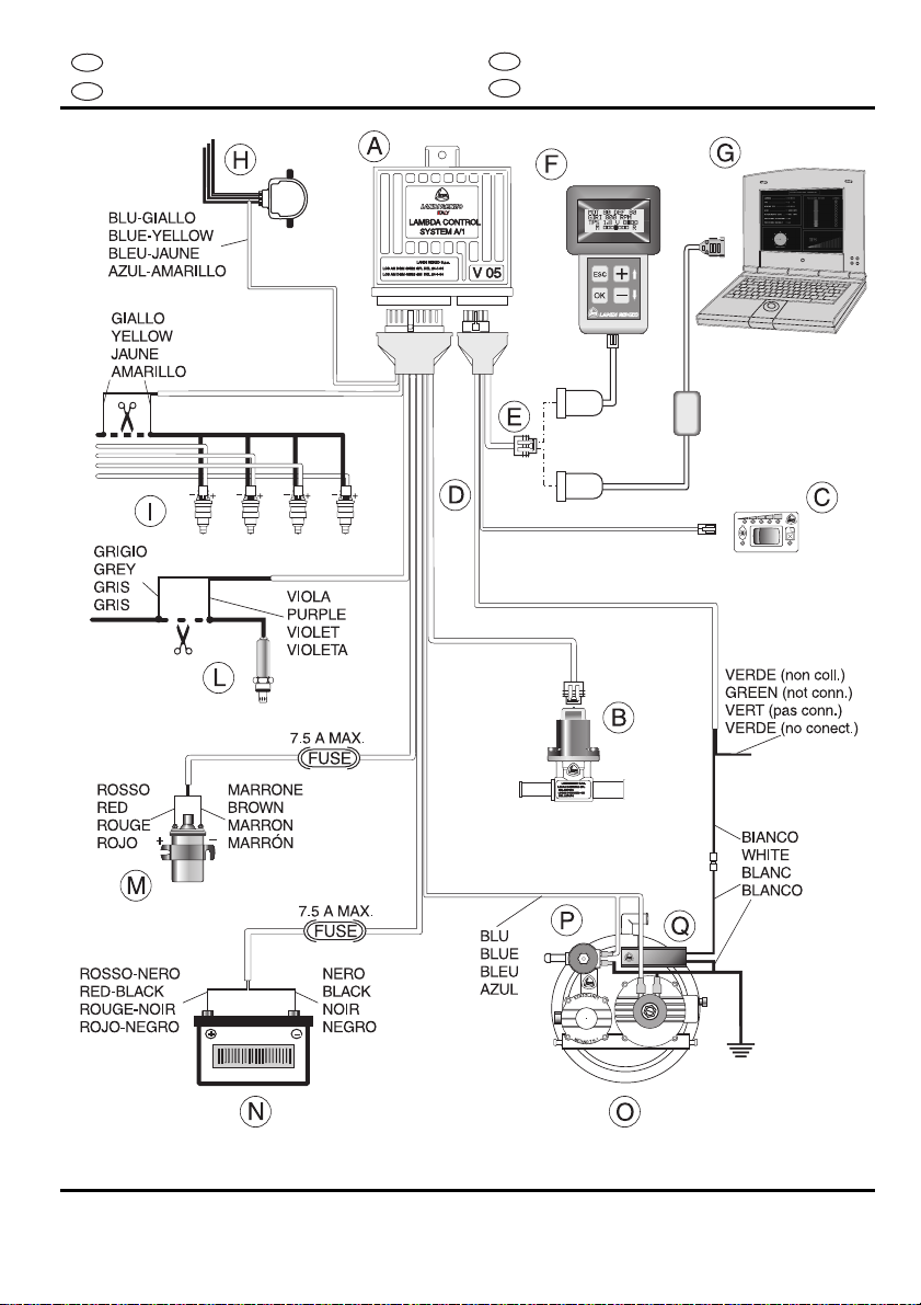
2. FUNZIONI DEL SISTEMA LCS A1 V05
Il sistema viene installato con i seguenti riduttori di
pressione GPL e metano LANDI RENZO: SE 81,
SE 81 SIC, TN1, TN1/B, TN1 SIC, TN1/B SIC.
Il Computer LCS A1 V05 elabora i segnali
provenienti dalla sonda lambda, dall'accensione,
dal sensore posizione farfalla d'accelerazione TPS
e contiene in memoria un valore di tensione della
sonda lambda corrispondente alla miscela
stechiometrica che deve essere mantenuta per
ogni condizione di funzionamento del motore.
La sonda lambda posta nel collettore di scarico
indica il rapporto di miscela ed in ogni istante invia
un valore di tensione al Computer LCS A1 V05 il
quale verifica se la miscela é corretta
confrontandolo con il valore posto in memoria; in
caso di differenza il Computer pilota l'Attuatore
Elettromeccanico Lineare variando opportuna-
mente la portata di gas fino a quando la miscela
rientra nei parametri lambda.
Le funzioni principali del LAMBDA CONTROL
SYSTEM A1 V05 sono le seguenti:
•Controllo e gestione della carburazione
durante il funzionamento a gas;
•Avviamento a benzina con commutazione
automatica del carburante;
•Possibilità di partenza in emergenza a gas
agendo semplicemente sul commutatore;
•Dispositivo di sicurezza che interrompe
l'alimentazione delle elettrovalvole gas in caso di
spegnimento anche accidentale del motore;
•Relè incorporato per l'interruzione
dell'iniezione benzina con ritorno automatico al
funzionamento a benzina in caso di avaria del
sistema LCS A1 V05;
•Funzione di ‘Start-Petrol’: l’Attuatore elettro-
meccanico lineare chiude il condotto del gas
durante il funzionamento a benzina ed a motore
spento;
•Sistema di dialogo (con presa diagnostica)
tramite Tester - Programmatore V05 oppure Kit
Interfaccia V05 con software dedicato ed
interfaccia seriale per personal computer.
Installazione componenti
I
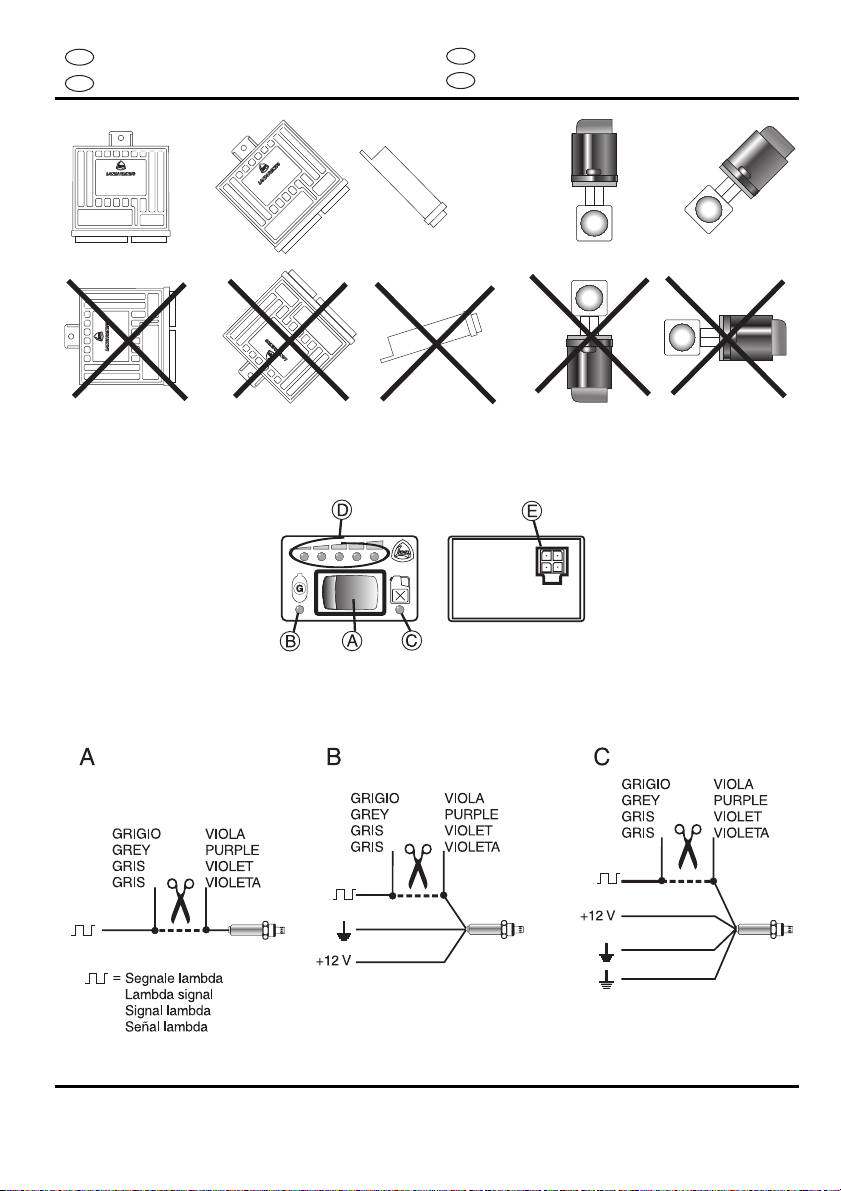
3. INSTALLAZIONE COMPUTER LCS A1 V05
(Fig. 3)
Il Computer deve essere fissato alla carrozzeria
del veicolo all’interno del vano motore secondo le
seguenti indicazioni:
•togliere i fusibili posti sul cablaggio prima di
procedere all’installazione dei componenti e
reinserirli ad installazione ultimata;
•il Computer dovrà essere posizionato lontano
da fonti di calore (es.: collettore di scarico,
radiatori, ecc.), al riparo da spruzzi d’acqua e
lontano dai cavi alta tensione dell’accensione;
•il lato dei connettori del Computer deve essere
rivolto verso il basso per evitare che eventuali
infiltrazioni di acqua penetrino all’interno del
Computer.
4. INSTALLAZIONE ATTUATORE ELETTRO-
MECCANICO LINEARE (Fig. 4)
L’Attuatore Elettromeccanico Lineare deve essere
installato preferibilmente all’ingresso del
miscelatore (al fine di ottimizzare la funzione di
cut-off) oppure, in alternativa, lungo il tubo di
alimentazione gas o sull’uscita gas del riduttore.
Inserire lo spinotto maschio proveniente dal
Computer LCS A1 V05 al connettore presente
sull’Attuatore Elettromeccanico Lineare.
IMPORTANTE: non posizionare mai l’Attuatore
Elettromeccanico Lineare con il motorino passo-
passo rivolto verso il basso od in modo che
eventuali depositi di olio possano penetrare
all’interno del meccanismo.
5. INSTALLAZIONE E FUNZIONAMENTO
COMMUTATORE / INDICATORE LCS A1 V05
(Fig. 5)
Installare il Commutatore / indicatore LCS A1 V05
nel cruscotto del veicolo secondo le seguenti
modalità:
•inserire il Commutatore / indicatore LCS A1
V05 in un foro inutilizzato di dimensioni idonee già
presente nel cruscotto del veicolo;
•inserire il Commutatore / indicatore LCS A1
V05 nel cruscotto del veicolo dopo aver ricavato
tramite l’apposito tranciante per commutatore
LANDI RENZO un foro rettangolare di dimensioni
idonee (circa 25x38 mm);

LANDI RENZO S.p.A.
MANUALE INSTALLAZIONE E REGOLAZIONE LAMBDA CONTROL SYSTEM A1 V05
8 / 33
I
Installazione componenti
•posizionare il Commutatore / indicatore LCS
A1 V05 nel cruscotto del veicolo utilizzando il
supporto esterno fornito in dotazione.
5.1 SPECIFICHE FUNZIONAMENTO COMMU-
TATORE / INDICATORE LCS A1 V05
(A) selettore gas / benzina
•a 2 posizioni con indicazione carburante in
uso tramite i due led luminosi (B) e (C);
(B) led verde
•
acceso costantemente:
indica il regolare
funzionamento a gas;
•
lampeggio rapido:
indica lo stato di attesa
della commutazione automatica a gas in fase di
avviamento (che avviene sempre a benzina);
•
lampeggio lento:
indica il malfunzionamento
del sistema LCS A1 V05 durante l’utilizzo a gas
(vedi par. 5.3).
(C) led giallo
•
acceso costantemente:
indica il funziona-
mento a benzina.
(D) serie led
•indicano il livello di gas (suddiviso in quarti)
presente nel serbatoio; il led rosso segnala la
riserva.
(E) connettore
•collega il commutatore al cablaggio
proveniente dal Computer LCS A1 V05.
5.2 PARTENZA IN EMERGENZA A GAS CON
COMMUTATORE / INDICATORE LCS A1 V05
Nel caso in cui sopravvengano problemi in fase di
avviamento a benzina (es. rottura pompa benzina,
ecc.), è possibile avviare il motore direttamente a
gas seguendo le sottoindicate istruzioni:
•Girare la chiave di accensione dell’auto ed
accendere il quadro;
•Portare il commutatore (A) in posizione
benzina e riportarlo in posizione gas senza
effettuare l’avviamento;
•A questo punto il led verde (B) rimane acceso
costantemente;
•Effettuare l’avviamento (senza spegnere il
quadro). In questa condizione il veicolo parte
direttamente a gas.
Collegamenti elettrici
6. COLLEGAMENTI ELETTRICI LCS A1 V05
Effettuare tutti i collegamenti sottoindicati con
saldature a stagno isolando i fili in modo
adeguato.
6.1FILI ROSSO-NERO E NERO (part. NFig. 1e 2)
ALIMENTAZIONE COMPUTER LCS A1 V05
Per fornire in modo continuo l’alimentazione al
sistema, effettuare i seguenti collegamenti del
cablaggio LCS A1 V05:
- filo rosso-nero:
collegato al positivo batteria
- filo nero:
collegato al negativo batteria
Nel caso in cui il veicolo sia provvisto di batteria
nel vano bagagliaio, collegare il filo rosso-nero al
polo positivo che si trova nel vano motore e
collegare il filo nero ad un punto di massa comune
originale dell’impianto elettrico dell’auto (es.
massa del computer benzina o massa di altri
dispositivi come ABS, idroguida, ecc.).
6.2 FILI GRIGIO E VIOLA (Fig. 6)
COLLEGAMENTO SONDA LAMBDA
Il collegamento della sonda lambda al cablaggio
LCS A1 V05 viene generalmente effettuato tramite
l’interruzione del filo del segnale lambda ed il
collegamento dei due capi ottenuti ai rispettivi
fili
grigio
e
viola
del computer LCS A1 V05.
Su specifici modelli di auto può essere invece
necessario collegare solo il filo
viola
del computer
LCS A1 V05 senza interrompere il filo della sonda,
mentre il filo
grigio
deve essere adeguatamente
isolato.
Le modalità di collegamento della sonda lambda al
computer sono riportate caso per caso nelle
SCHEDE AUTO del Servizio Assistenza Tecnica
LANDI RENZO.
Al fine di facilitare l’individuazione del filo del
segnale lambda, qui di seguito sono elencate le
più comuni tipologie di sonda lambda:
•
sonda lambda ad 1 filo :
individuare il filo che
proviene dalla sonda lambda e giunge al computer
benzina (Fig. 6A);
•
sonda lambda a 2 fili :
individuare il filo del
segnale lambda utilizzando un tester multimetro:
su tale filo la tensione rispetto alla massa varia da
0÷1V, da 0,8÷1,6V oppure da 0÷5V;

LANDI RENZO S.p.A.
MANUALE INSTALLAZIONE E REGOLAZIONE LAMBDA CONTROL SYSTEM A1 V05
9 / 33
Collegamenti elettrici
•
sonda lambda a 3 fili :
individuare il filo del
segnale lambda come da punto precedente. Gli
altri due fili sono utilizzati per il riscaldamento della
sonda lambda: uno presenta una tensione di +12V
e l’altro è un negativo (Fig. 6B);
•
sonda lambda a 4 fili :
individuare il filo del
segnale lambda come da punto precedente. Altri 2
fili sono utilizzati per il riscaldamento della sonda
lambda (vedi punto precedente), mentre un filo è il
negativo del segnale della sonda lambda (Fig.
6C).
6.3 FILO BLU-GIALLO (Fig. 7)
COLLEGAMENTO AL SEGNALE DEL TPS
Il segnale del TPS indica al computer benzina in
quale posizione si trova la farfalla di
accelerazione. Il collegamento del TPS al
cablaggio LCS A1 V05 viene effettuato secondo le
seguenti modalità:
•
TPS proporzionale
(Fig. 7A)
:
il segnale in
uscita da questo sensore ha una tensione che
varia proporzionalmente rispetto alla posizione
della farfalla. Su questo tipo di sensore sono
presenti 3 fili:
- un filo ha una tensione di alimentazione di +5V (a
quadro inserito);
- un filo è collegato al negativo batteria;
- un filo è il segnale in uscita del TPS e deve
essere collegato al filo blu-giallo del cablaggio
LCS A1 V05. La tensione all’estremità di questo
filo varia rispetto alla massa da 0 a 5V.
•
TPS di tipo "switch"
(Fig. 7B)
:
i fili presenti su
questo sensore sono simili a quelli presenti su di
un TPS proporzionale come sopra descritto. Il
segnale in uscita da questo TPS presenta
solamente 2 condizioni: 0 Volt a farfalla chiusa, 12
Volt con farfalla in condizione di fuori minimo, o
viceversa. Identificare il filo che costituisce il
segnale in uscita del TPS con l’impiego di un
tester multimetro (assicurandosi di effettuare le
misure riferite a massa) e collegarlo al filo blu-
giallo del cablaggio LCS A1 V05.
Collegamenti elettrici
I
6.4 FILO MARRONE (part. M Fig. 1e 2)
COLLEGAMENTO AL SEGNALE NUMERO GIRI
MOTORE (RPM)
Collegare il filo marrone del cablaggio LCS A1 V05
al negativo della bobina di accensione o, in
alternativa, al filo del contagiri del veicolo secondo
le seguenti modalità:
•collegamento al negativo bobina
di un veicolo
con motore 4 cilindri dotato di
2 bobine
o di
bibobina:
impostare il Computer LCS A1 V05 alla
voce ‘NUMERO CILINDRI / TIPO ACCENSIONE’
ÌBIBOBINA
•collegamento al negativo bobina
di un veicolo
dotato di
una bobina
che alimenta tutti i cilindri
attraverso lo spinterogeno: impostare il Computer
LCS A1 V05 alla voce ‘NUMERO CILINDRI / TIPO
ACCENSIONE’ ÌMONOBOBINA
In entrambi i casi sopra indicati non si deve
impostare il parametro relativo al numero di
cilindri. Al contrario, nel caso in cui il sistema di
accensione del veicolo abbia lo spinterogeno
oppure nel caso in cui si effettui un collegamento
al contagiri del veicolo stesso, è necessario
definire il numero cilindri (e non impostare il tipo di
bobina).
6.5 FILO ROSSO (part. M Fig. 1e 2)
COLLEGAMENTO 12V SOTTOCHIAVE
Collegare il filo rosso del cablaggio LCS A1 V05
ad un dispositivo sottochiave come ad esempio il
positivo della bobina di accensione oppure ad un
altro filo che fornisca la tensione di 12V a quadro
inserito.
6.6 FILI BIANCO E VERDE (Fig. 8)
COLLEGAMENTO AL SENSORE LIVELLO GAS
Il Computer LCS A1 V05 può essere abbinato a
diversi sensori livello gas in commercio secondo le
seguenti modalità:
- sensore Gpl/Metano tipo LANDI RENZO
:
collegare il filo bianco del cablaggio LCS A1 V05
al filo bianco del sensore livello gas e non
collegare il filo verde (il cui estremo dovrà essere
isolato).
- sensore tipo A.E.B.
: collegare i fili verde e bianco
del cablaggio LCS A1 V05 ai rispettivi fili verde e
bianco del sensore livello gas.

LANDI RENZO S.p.A.
MANUALE INSTALLAZIONE E REGOLAZIONE LAMBDA CONTROL SYSTEM A1 V05
10 / 33
I
Collegamenti elettrici
- sensore tipo 0-90 Ω:
collegare entrambi i fili
verde e bianco del cablaggio LCS A1 V05 al filo
del sensore livello gas.
6.7 FILI GIALLI (Fig. 9)
DISINSERIMENTO DEGLI INIETTORI
I fili gialli del cablaggio LCS A1 V05 sono collegati
ai contatti di un relè normalmente chiuso.
Durante il funzionamento a gas, (Fig. 9A) i contatti
del relè si aprono impedendo agli iniettori benzina
di funzionare, mentre quando il motore è
alimentato a benzina, i contatti restano chiusi.
Impostare il Computer LCS A1 V05 alla voce
‘TEMPO DI SOVRAPPOSIZIONE’ il tempo
desiderato (in secondi) di ritardo dell’apertura dei
contatti in modo da avere un’adeguata
sovrapposizione dei carburanti in fase di
commutazione da benzina a gas. La corrente
massima applicabile come carico continuo è di
6,5A.
Nel caso in cui, per disinserire gli iniettori, si
impieghi un emulatore elettronico (Fig. 9B) e sia
necessario impostare un determinato ritardo per
regolare la sovrapposizione dei carburanti,
collegare un’estremità dei fili gialli del cablaggio
LCS A1 V05 a massa e l’altra estremità alla
apposita presa sull’emulatore elettronico.
NOTA: durante il funzionamento a gas, in caso di
eventuale malfunzionamento del sistema di
disinserimento degli iniettori, il sistema LCS A1
V05 commuterà automaticamente l’alimentazione
a benzina.
Funzionamento di LCS A1 V05
7. FUNZIONAMENTO DI LCS A1 V05
Le funzioni programmabili di LCS A1 V05 possono
essere modificate solamente tramite l’ apposito
Tester Programmatore V05 o personal computer
con Kit Interfaccia V05 installato e relativo
software dedicato.
Anche quando il Computer LCS A1 V05 non è
alimentato (es. batteria staccata) le funzioni
immesse restano in
memoria
.
Per maggiori dettagli fare riferimento al ‘Manuale
di istruzioni Tester Programmatore V05’.
7.1 DATI VISUALIZZATI
Tramite il Tester Programmatore V05 (o personal
computer con Kit Interfaccia V05 installato
)
si
visualizzano i seguenti dati:
•ATT: indica (in numero di passi) la posizione in
tempo reale dell’Attuatore Elettromeccanico
Lineare
•DEF: indica (in numero di passi) la posizione di
default acquisita (valore standard) dell’Attuatore
Elettromeccanico Lineare
•GIRI: indica (in rpm) il numero di giri del motore
in tempo reale
•TPS: indica (in volt) la posizione del sensore
posizione farfalla di accelerazione
•CAMPI APPRENDIMENTO TPS: indicano se si
è in fase di minimo, di velocità di crociera o di
massima apertura farfalla di accelerazione
•CAMPI APPRENDIMENTO SONDA LAMBD :
indicano se si è in fase di miscela povera o ricca
Con il Computer LCS A1 V05 nuovo o appena
resettato la posizione ‘DEF’ di default
dell’Attuatore Elettromeccanico Lineare è di
100
passi.
La
posizione del minimo TPS
e la
posizione di
default
dell’Attuatore Elettromeccanico Lineare
vengono acquisite ad ogni accensione del
sistema; l’ultimo default acquisito viene utilizzato
come posizione di partenza.

LANDI RENZO S.p.A.
MANUALE INSTALLAZIONE E REGOLAZIONE LAMBDA CONTROL SYSTEM A1 V05
11 / 33
Funzioni programmabili di
LCS A1 V05
7.2 FUNZIONI PROGRAMMABILI DI LCS A1 V05
Nel prospetto sotto riportato vengono indicate le
funzioni programmabili di LCS A1 V05 con il
relativo menu e sotto-menu di programmazione in
cui sono evidenziati in carattere neretto i
parametri standard impostati con Computer nuovo
o resettato.
- NUMERO CILINDRI / TIPO ACCENSIONE:
BIBOBINA, MONOBOBINA, 4/5/6/8 CILINDRI
- SEGNALE RPM:
STANDARD, DEBOLE
- CAMBIO BENZINA/GAS:
IN DECELERAZIONE, IN ACCELERAZIONE,
PARTENZA A GAS (solo se abilitata)
- TEMPO DI CICCHETTO: (solo se abilitata partenza a
gas)
0,0 – 5,0 sec (0,8 sec)
-TEMPERATURA PER CAMBIO: (solo se abilitata)
20° - 40° (30°)
- RPM PER CAMBIO:
400 - 9.000 RP (2.000 RPM)
- TEMPO SOVRAPPOSIZIONE CARBURANTI:
0,000 - 1,000 SEC. (0,400 SEC.)
- TPS (SENSORE POSIZIONE FARFALLA ACCELERA-
ZIONE):
LINEARE 0-5V, LINEARE 5 - 0V, SWITCH 0 -
12V, SWITCH 12 - 0V, MONO BOSCH, TPS ADAPTER
- SENSORE LIVELLO GAS:
LANDI RENZO, A.E.B., 0-90 OH
- SONDA LAMBDA:
0 - 1V, 0,8 - 1,6V, 0 - 5V ‘A’, 0 - 5V ‘B’,
5 - 0V ‘A’, 5 - 0V ‘B,
- RITARDO LETTURA SONDA LAMBDA:
0 - 1.250 SEC. (5 SEC.)
- EMULAZIONE SONDA LAMBDA:
ONDA QUADRA, SCONNESSA, MASSA
- EMULAZIONE ONDA QUADRA (solo se selezionata
dalla prec. opzione):
TEMPO DI ALTO (0,36 SEC.),
TEMPO DI BASSO (0,36 SEC.), TEMPO SONDA
SCONNESSA (0,00 SEC.), NUMERO ONDE DOPO
SCONNESSIONE
(0)
- SCOSTAMENTO ATTUATORE-MAX IN ACCELERA-
ZIONE:
NON
ABILITATA, 20 - 240 PASSI (100 PASSI se
abilitata)
- TPS PER SCOSTAMENTO (solo se abilitata
precedente opzione):
1,5 - 5,0V (2,8V)
- MASSIMA APERTURA ATTUATORE-MAX:
20 - 240 PASSI (240 PASSI )
Funzioni programmabili di
LCS A1 V05
I
- TPS PER RILASCIO LIMITAZIONI: (solo se abilitate
relative opzioni)
0,0 - 5,0V (2,8V)
- MINIMA APERTURA ATTUATORE-MAX:
20 - 240 PASSI (20 PASSI)
- OPZIONE CUT-OFF:
NON
ABILITATA, ABILITATA
- RPM MINIMI PER CUT-OFF (solo se abilitata prec.
opzione):
400 - 9.000 RP (1.500 RPM)
- POSIZIONE ATTUATORE-MAX IN CUT-OFF (solo se
abilitata prec. opzione):
40 - 240 PASSI (80 PASSI)
- INCREMENTO ATTUATORE-MAX IN ACCELERA-
ZIONE:
NON
ABILITATA, ABILITATA
- VARIAZIONE TPS PER INCREMENTO: (solo se
abilitata prec. opzione)
0,1 - 3,0V (0,3V)
- NUMERO PASSI INCREMENTO: (solo se abilitata
prec. opzione)
0 – 30 PASSI (5 PASSI)
- POSIZIONE ATTUATORE-MAX PER DEFAULT FISSO:
NON
ABILITATA, 20 - 240 PASSI (100 PASSI se
abilitata)
- RESET MEMORIA LCS A1 V05: OK PER CONFERMA
consente di ripristinare le impostazioni standard (valori in
carattere neretto) del Computer LCS A1 V05
7.3 NOTE RELATIVE ALLA PROGRAMMAZIONE
DI LCS A1 V05
L’emulazione standard della sonda lambda è
impostata TIPO DI EMULAZIONE ÌONDA
QUADRA. Questo tipo di emulazione viene
impiegato per la maggior parte delle auto e deve
essere cambiato solo se prescritto dal MANUALE
TECNICO LANDI RENZO SCHEDE AUTO
MT012.
L’emulazione della sonda lambda per veicoli dotati
di
Monoiniettore Bosch
(per i quali si imposta il
parametro TIPO DI TPS ÌMONO BOSCH) viene
effettuata programmando TIPO DI EMULAZIONE
ÌMASSA. In questi veicoli si collega il filo giallo-
blu del cablaggio LCS A1 V05 al filo n. 2 (anziché
al filo n. 4) del connettore TPS posto a fianco del
corpo farfallato.
Nel caso in cui si presentino
messaggi di errore
sul display del Tester Programmatore (o del
personal computer nel caso si utilizzi il Kit
Interfaccia V05) come ad esempio ‘PREMERE OK
PER RESETTAMENTO TESTER’, oppure nel

LANDI RENZO S.p.A.
MANUALE INSTALLAZIONE E REGOLAZIONE LAMBDA CONTROL SYSTEM A1 V05
12 / 33
I
Diagnosi anomalie di
Funzionamento
caso in cui non si riesca a dialogare con il
Computer LCS A1 V05, occorrerà
scollegare
entrambi i connettori del Computer stesso
lasciandoli scollegati per almeno 3 minuti in modo
da dare al sistema il tempo di scaricare i circuiti
interni. Dopodiché si potrà procedere con una
nuova programmazione.
7.4 DIAGNOSI ANOMALIE DI FUNZIONAMENTO
Il Commutatore / Indicatore LCS A1 V05 è in
grado di evidenziare all’installatore oppure
all’utente alcune condizioni di errore.
Qualora durante la marcia con commutatore in
posizione gas il led verde (lettera B Fig. 5) inizi a
lampeggiare lentamente, significa che si è
verificata una delle seguenti condizione di errore:
•la sonda lambda non funziona;
•la sonda lambda rileva la miscela ricca per
troppo tempo;
•la sonda lambda rileva la miscela povera per
troppo tempo;
Tali condizioni di errore, anche se non più
segnalate alle successive accensioni del veicolo,
vengono registrate nella memoria dell’LCS A1 V05
in modo permanente.
Con l’impiego dell’apposito Tester Programmatore
o Kit Interfaccia V05 si visualizza (alla voce
‘DIAGNOSI’) il tipo di errore e, una volta effettuato
l’intervento risolutivo del problema, occorre
cancellarlo dalla memoria.
8. PROCEDURA PER L'APPRENDIMENTO
DELLA CARBURAZIONE CON LCS A1 V05
Per l’apprendimento della carburazione con LCS
A1 V05 seguire le sottoindicate istruzioni:
a) Inserire i fusibili sui cablaggi (fusibili tolti in fase
di installazione di LCS A1 V05).
b) Collegare il Tester Programmatore V05 (oppure
il personal computer con Kit Interfaccia V05
installato) alla presa di diagnosi e
programmazione situata sul cablaggio del
Computer LCS A1 V05.
c) Tramite il Tester Programmatore V05 (oppure il
personal computer) adeguare opzione per opzione
i parametri del Computer LCS A1 V05 alle
specifiche del veicolo (vedipar. 7.2).
Procedura apprendimento
carburazione
d) Verificare di aver memorizzato nel Computer
LCSA1V05 le opzioni esattamente corrisponden-ti
alle caratteristiche del veicolo. In caso contrario,
effettuare il reset della memoria del Computer LCS
A1 V05 e verificare che assuma i valori standard
evidenziati in neretto nel paragrafo 7.2;
adeguare successivamente un’altra volta i
parametri del Computer LCS A1 V05 alle
specifiche del veicolo e ripetere la verifica.
e) Avviare il motore con il Commutatore /
indicatore LCS A1 V05 in posizione benzina ed
attendere qualche minuto per permettere alla
sonda lambda di scaldarsi.
f) Entrare nella ‘pagina’ VISUALIZZA del Tester
Programmatore (o del personal computer).
g) Ad auto ferma, commutare a gas ed effettuare
una serie di accelerazioni e decelerazioni
intervallate di qualche secondo; in questo modo il
Computer LCS A1 V05 apprenderà la posizione
del minimo TPS.
h) A questo punto si regola il massimo del
riduttore: portare il motore a circa 3.500 giri/min.
fino ad apprendimento del valore di default (la
voce ‘DEF’ visualizzata sul display del Tester
Programmatore cambierà di valore).
i) Successivamente si regola il minimo del
riduttore: con il motore in moto, ruotare il registro
del minimo del riduttore fino a quando, sul Tester
Programmatore V05 (o del personal computer), il
numero dei passi dell’Attuatore Elettromeccanico
Lineare riportato nel menù ‘Visualizza’ alla voce
‘ATT’ sarà uguale (od il più vicino possibile) al
valore indicato alla voce ‘DEF’.
l) Verificare che oscillino regolarmente i led della
scala lambda che indicano la carburazione.
m) Controllare con l’analizzatore gas di scarico
che il valore lambda sia uguale a circa 1,000 e che
i valori di CO, HC e CO2siano come da tabelle
riportate nelle istruzioni di installazione e
regolazione dei riduttori LANDI RENZO.
n) Registrati il minimo ed il massimo, effettuare un
test su strada.
Dati, descrizioni e illustrazioni hanno solo valore
indicativo e LANDI RENZO S.p.A. si riserva il
diritto di apportare, a suo criterio e senza
preavviso, migliorie o modifiche.

LANDI RENZO S.p.A.
INSTALLATION AND ADJUSTMENT MANUAL LAMBDA CONTROL SYSTEM A1 V05
13 / 33
Legend
LAMBDA CONTROL SYSTEM A1 V05 is a self-
adjusting electronic system to control the gas
supply (Lpg or Cng) of vehicles equipped with a
lambda sensor and catalytic converter: it requires
no manual adjustments and can automaticall
adapt to the different environmental conditions and
use of the vehicle so as to ensure optimum
carburation in terms of driving, consumption and
emissions.
LEGEND (Fig. 1 Lpg; Fig. 2 Cng)
The system consists of the following components:
A) Computer LCS A1 V05
B) Linear Electromechanical Actuator
C) Switch/Gauge LCS A1 V05
D) Wiring harness to connect LCS A1 V05
Computer to relevant devices
E) Programming and diagnosis connector
Others elements represented in the diagram are:
F) Programming Tester V05
G) Personal computer with Interface Kit V05 (in
alternative to Programming Tester V05)
H) TPS (Throttle position sensor)
I) Petrol injectors
L) Lambda sensor
M) Ignition coil
N) Batter
O) Gas solenoid
P) Pressure regulator
Q) Gas level sensor
The drawings shown in Fig. 1 and 2 concerning
the Lpg and Cng conversion system are indicative;
for specific situations concerning the electrical
connections, see paragraph 6.
Specification
GB
1. TECHNICAL SPECIFICATION
1.1 COMPUTER LCS A1 V05
•
Electrical specifications
- Power supply:
12V (-20% / +30%)
- Max. power absorption during operation:
0,6A
- Max. power applicable to the relay to interrupt
petrol injection (yellow wires):
6,5A
- Max. power output for gas control devices (blue
wires):
6,5A
- Water and dust protection level:
IP65
•
Programmable functions
- Number of cylinders / type of ignition
- Type of engine rpm signal
- Type automatic petrol/gas change
- Rpm number for automatic change
- Fuel overlapping time during automatic change
- TPS type (throttle position sensor)
- Gas level sensor type
- Type lambda sensor
- Lambda sensor reading dela
- Type of lambda sensor emulation
- Max. open throttle position during acceleration
- Min / max. actuator opening
- Cut-off option
- Fixed default option
- Memory resetting
1.2 LINEAR ELECTROMECHANICAL
ACTUATOR
•
Electrical specifications
- Power supply:
12V
- Power absorption:
150mA
- Nominal power:
2W
- Operating temperature:
-20°C / +120°C
- Water and dust protection level:
IP65

LANDI RENZO S.p.A.
INSTALLATION AND ADJUSTMENT MANUAL LAMBDA CONTROL SYSTEM A1 V05
14 / 33
GB
Functions
2. LCS A1 V05 FUNCTIONS
LCS A1 V05 is used with following Lpg or Cng
LANDI RENZO pressure regulator: SE 81, SE 81
SIC, TN1, TN1/B, TN1 SIC, TN1/B SIC.
The LCS A1 V05 Computer processes the signals
from the lambda sensor, ignition, throttle position
sensor TPS and holds in memory a lambda sensor
tension value corresponding to the stoichiometric
mixture that needs to be maintained for ever
operating condition of the engine.
The lambda sensor in the exhaust manifold
indicates the mixture ratio and at every moment
sends a value of voltage to the LCS A1 V05
Computer which checks whether the mixture is
correct by comparing it with the value set in
memory; if there is a difference, the computer will
drive the Linear Electromechanical Actuator,
suitably changing the rate of flow of gas until the
mixture comes back into the lambda stoichiometric
value.
The main functions of the LAMBDA CONTROL
SYSTEM A1 V05 include:
•control of carburation during gas operation;
•petrol starting with automatic switch over to
gas;
•possibility of emergency gas starting by simple
operation on the switch;
•electronic safety device that cuts off gas
solenoid valve supply in the event of the engine
accidentally stalling;
•built-in relay to cut off petrol injection with
automatic change over to petrol in case of LCS A1
V05 damage;
•‘Petrol-Start’ function: the Linear
Electromechanical Actuator closes the gas line
while running on petrol and when the engine is
stopped.
•interface system (using a diagnostic
connector) with a diagnostic and programming
instrument Programmer - Tester V05 or Interface
Kit V05 with dedicated software and serial
interface for personal Computer.
Parts installation
3. INSTALLATION OF COMPUTER LCS A1 V05
(Fig. 3)
The Computer must be attached to the car chassis
inside the engine compartment according following
instructions:
•remove the fuses located on the wiring before
installing the parts and replace them once
installation has been completed;
•position the Computer away from sources of
heat (exhaust header, radiators, etc.), protected b
water and away from ignition high voltage wires;
•position the Computer with the connector side
facing down to prevent any water droplets from
penetrating inside the control unit through the
connectors.
4. INSTALLATION OF THE LINEAR ELECTRO-
MECHANICAL ACTUATOR (Fig. 4)
The Linear Electromechanical Actuator must be
installed preferably at the mixer inlet (in order to
optimise the cut-off function) or, in alternative,
along the gas hose or on the regulator outlet.
Insert the male pin coming from the LCS A1 V05
computer to the connector on the Actuator.
IMPORTANT: never position the Linear
Electromechanical Actuator with the motor facing
down or in such a way that oil deposits can
penetrate inside the motor.
5. INSTALLATION AND OPERATION OF
SWITCH / GAUGE LCSA1 V05 (Fig. 5)
Install the Switch / Gauge LCS A1 V05 on the
dashboard according following possibilities:
•insert the Switch / Gauge LCS A1 V05 in an
existing hole with suitable dimensions;
•insert the Switch / Gauge LCS A1 V05 in the
dashboard after making a rectangular hole (about
25x38 mm) with the LANDI RENZO cutting device
for switches;
•position the Switch / Gauge LCS A1 V05 in the
dashboard by using the external support provided.

LANDI RENZO S.p.A.
INSTALLATION AND ADJUSTMENT MANUAL LAMBDA CONTROL SYSTEM A1 V05
15 / 33
Parts installation
5.1 SWITCH / GAUGE LCS A1 V05 OPERATION
EXPLANATION
(A) gas / petrol selector
•with 2 position and indication of used fuel b
mean of 2 leds (B) and (C);
(B) green led
•
turned on:
indicates the car is regularl
running on gas;
•
rapid flashing:
indicates the stand by for the
automatic change over during the starting (that is
always on petrol);
•
slow flashing:
indicates the malfunctioning of
LCS A1 V05 during gas operation (see par. 5.3).
(C) yellow led
•
turned on:
indicates the car is running on
petrol.
(D) led series
•indicates the level of gas (divided into fourths)
present in the tank: the red led indicates the car is
running on reserve.
(E) connector
•connect the switch to the wires coming from
the LCS A1 V05 Computer.
5.2 EMERGENCY STARTING ON GAS WITH
SWITCH / GAUGE LCS A1 V05
In case of malfunctioning during the petrol starting
(ex. petrol pump damage, etc.), it is possible to
start directly on gas following listed instruction:
•Turn the ignition key until the board is turned
on;
•Set the switch (A) to the petrol position and
return it to the gas position without starting;
•Now the green led (B) turns on;
•Start the vehicle (without turn off the board). In
this condition the vehicle begin running directl
with gas.
Electrical connections
GB
6. LCS A1 V05 ELECTRICAL CONNECTIONS
It is recommended to solder listed wire
connections and insulate them properly.
6.1 RED-BLACK AND BLACK WIRES (lt. N Fig. 1
and 2) COMPUTERLCSA1V05 POWER SUPPL
To deliver a continuous power to the system,
made following connections of LCS A1 V05 wiring:
- red-black wire:
connect to the battery positive
- black wire:
connect to the battery negative
In the case the vehicle has the battery in the
luggage compartment, connect the red-black wire
to the positive pole in the engine compartment and
the black wire to an original common earth of the
electric equipment of the vehicle (ex. earth of the
petrol computer or other devices such as ABS,
power steering, etc.)
6.2 GREY AND VIOLET WIRES (Fig. 6)
LAMBDA SENSOR CONNECTION
The connection of the lambda sensor to the LCS
A1 V05 wiring is generally made by connecting
both the
violet
than the
grey
wires
of the LCS A1
V05 Computer on the outlet signal of lambda
sensor.
In some model of vehicles it could be necessary to
connect only the
violet wire
of the LCS A1 V05
Computer, while the
grey
one will be properl
insulated.
The explanation are shown case per case in the
TECHNICAL SHEET of the Technical Assistance
Service
LANDI RENZO
.
In order to facilitate the identification of the lambda
signal wire, herebelow are listed the most common
type of lambda sensor:
•
one-wire lambda sensor:
individuate the wire
that from the lambda sensor reaches the petrol
computer (Fig. 6A);
•
two-wire lambda sensor:
use a tester to
individuate the lambda signal wire: on this wire the
voltage with respect to ground could varies
between 0÷1V, 0,8÷1,6V or 0÷5V);

LANDI RENZO S.p.A.
INSTALLATION AND ADJUSTMENT MANUAL LAMBDA CONTROL SYSTEM A1 V05
16 / 33
GB
Electrical connections
•
three-wires lambda sensor:
individuate the
lambda signal wire as previous point. The other 2
wires are used to heat the sensor: one has a 12V
tension and the other is a negative (Fig. 6B).
•
four-wires lambda sensor:
individuate the
lambda signal wire as previous point. Other 2
wires are used to heat the sensor (see above),
while one wire is the negative of the lambda
sensor (Fig. 6C).
6.3 BLUE-YELLOW WIRE (Fig. 7)
TPS SIGNAL CONNECTION
The TPS signal communicates the position of the
acceleration throttle to the petrol computer. The
connection of the TPS to the LCS A1 V05 wiring is
made according following instructions:
•
Proportional TPS
(Fig.7A)
:
the output signal
from this sensor has a voltage that is proportional
to the throttle position. This type of sensor has 3
wires:
- one has a power supply voltage of +5V, with the
instrument panel on;
- one is connected to the battery negative;
- one is the sensor output and must be connected
to the blue-yellow wire of the LCS A1 V05. The
voltage at the ends of this wires, with respect to
ground, varies from 0 to 5V.
•
Switch type TPS
(Fig. 7B)
:
the wires on this
sensor are similar to those on a proportional TPS
above described. The output signal from this
sensor has only 2 conditions: 0 Volts with throttle
closed and 12 Volts with the throttle is in out of
idling condition or vice versa. Identify the wire that
is the output signal of TPS by means of a tester
(making sure that the measurements are
performed with reference to ground) and connect
the same to the blue-yellow wire of the LCS A1
V05.
Electrical connections
6.4 BROWN WIRE (lt. M Fig. 1 and 2)
ENGINE RPM SIGNAL CONNECTION
Connect the brown wire of LCS A1 V05 to the
negative of the ignition coil or, as an alternative, to
the speed indicator wire according following
instructions:
•connection to the coil negative of a vehicle
with a 4 cylinder engine with 2 coils or 1 double
coil: set the LCS A1 V05 Computer at the
parameter ‘NUMBER OF CYLINDERS / TYPE OF
IGNITION’ ÌDOUBLE COIL.
•connection to the coil negative of a vehicle
with one coil that supply all the cylinders by means
of a distributor: set the LCS A1 V05 Computer at
the parameter ‘NUMBER OF CYLINDERS / TYPE
OF IGNITION’ ÌMONO COIL.
In both cases you have not to set the parameter
concerning the number of cylinders. On the
contrary, in the case in which the ignition system
of the vehicle has a distributor or in the case you
made a connection to the speed indicator of the
vehicle, it is necessary to set the number of
cylinder (and not to set the type of coil).
6.5 RED WIRE (lt. M Fig. 1 and 2)
12V IGNITION KEY CONNECTION
Connect the red wire of LCS A1 V05 to a key
device such as the positive of the ignition coil or to
another wire that supplies 12V when the board is
turned on.
6.6 WHITE AND GREEN WIRES (Fig. 8)
CONNECTION TO THE GAS LEVEL SENSOR
The LCS A1 V05 Computer operates with different
gas level sensors available on the market
according following instructions:
- LANDI RENZO type Lpg/Cng sensor:
connect
the white wire of LCS A1 V05 to the white wire of
the gas level sensor; the green wire remains
disconnected, insulating its end.
- A.E.B.
type sensor:
connect both green and
white wires of LCS A1 V05 to the respective green
and white wires of the gas level sensor.
- 0-90 Ωtype sensor:
connect both green and
white wires of LCSA1 V05 to the gas level sensor
wire.

LANDI RENZO S.p.A.
INSTALLATION AND ADJUSTMENT MANUAL LAMBDA CONTROL SYSTEM A1 V05
17 / 33
Electrical connections
LCS A1 V05 operation
6.7 YELLO WIRES (Fig. 9)
DISCONNECTING THE INJECTORS
The yellow wires of LCS A1 V05 are connected to
the contacts of a normally closed relay. During gas
operation, (Fig. 9A) the contacts of the relay open,
thus preventing the injectors from operating; when
the engine is fed with petrol, these contacts remain
closed.
Set the LCS A1 V05 Computer at the parameter
‘OVERLAP TIME’ preferable retard timing (in
seconds) of the contacts open in order to have a
suitable fuel overlapping during change from petrol
to gas. The maximum applicable current as a
continuous load is 6.5 A.
If an
electronic emulator
is used to disconnect the
injectors (Fig. 9B) and it is necessary to set a fuel
overlapping time, connect one end of the yello
wires of LCS A1 V05 to ground and the other to
the special connector on the electronic emulator.
NOTE: during gas operation, in case of eventual
malfunctioning of the injector disconnection
system, LCS A1 V05 will change automatically on
petrol.
7. LCS A1 V05 OPERATION
The programmable functions of LCS A1 V05 can
be set only by the Programmer Tester V05 or by a
personal computer with Interface Kit V05 and
dedicated software.
Also when the LCS A1 V05 is not fed (ex. batter
disconnected), the memorised functions are
stored.
For more details, see the ‘Instruction Manual
Programmer Tester V05’.
Data display
LCS A1 V05 progr. functions
GB
7.1 DATA DISPLAY
By the Programmer Tester V05 (or personal
computer with Interface Kit V05 installed) following
data are displayed:
•ACT: indicates (in number of steps) the actual
position of the Linear Electromechanical
Actuator
•DEF: indicates (in number of steps) the acquired
default position (standard value) of the Linear
Electromechanical Actuator
•RPM: indicates (in rpm) the actual number of
revolutions of the engine
•TPS: indicates (in volt) the position of the throttle
position sensor
•TPS LEARNING RANGE: indicate if you are in
an idling condition, cruise condition or maximum
open throttle condition
•LAMBDA SENSOR LEARNING RANGE:
indicate if you are in a poor or rich mixture
condition
With LCS A1 V05 Computer new or resetted the
‘DEF’ position of the Linear Electromechanical
Actuator is
100 steps
.
The
minimum TPS position
and the
default
position
of the Linear Electromechanical Actuator
are acquired at every ignition of the system; the
last acquired default is used as starting position.

LANDI RENZO S.p.A.
INSTALLATION AND ADJUSTMENT MANUAL LAMBDA CONTROL SYSTEM A1 V05
18 / 33
GB
LCS A1 V05 progr. functions
7.2 LCS A1 V05 PROGRAMMABLE FUNCTIONS
Here below are indicated the programmable
functions of LCS A1 V05 with relevant
programming menu and options in which are
pointed out in bold type the standard parameters
settled with Computer new or resetted.
- NUMBER OF CYLINDER / TYPE OF IGNITION:
DOUBLE-COIL, SINGLE-COIL, 4/5/6/8 CYLINDERS
- RPM SIGNAL:
STANDARD, WEAK
- PETROL/GAS AUTOMATIC CHANGE:
IN DECELERATION, IN ACCELERATION, GAS
STARTING (only if enabled)
- PRIMING TIME: (only if enabled gas starting)
0,0 – 5,0 sec (0,8 sec)
- TEMPERATURE FOR CHANGE: (only if enabled)
20° - 40° (30°)
- RPM FOR AUTOMATIC CHANGE:
400 - 9.000 RP (2.000 RPM)
- FUEL OVERLAPPING TIME DURING AUTOMATIC
CHANGE:
0,000 - 1,000 SEC. (0,400 SEC.)
- TPS (THROTTLE POSITION SENSOR):
LINEAR 0-5V, LINEAR 5 - 0V, SWITCH 0 - 12V,
SWITCH 12 - 0V, MONO BOSCH, TPS ADAPTER
- GAS LEVEL SENSOR:
LANDI RENZO, A.E.B., 0-90 OH
- LAMBDA SENSOR:
0 - 1V, 0,8 - 1,6V, 0 - 5V ‘A’, 0 - 5V ‘B’,
5 - 0V ‘A’, 5 - 0V ‘B,
- LAMBDA SENSOR READING DELAY:
0 - 1.250 SEC. (5 SEC.)
- LAMBDA SENSOR EMULATION:
SQUARE WAVE, DISCONNECTED, GROUND
- SQUARE WAVE EMULATION (only if selected previous
option):
HIGH TIM (0,36 SEC.), LOW TIME (0,36 SEC.),
DISCONNECTED SENSOR TIME (0,00 SEC.), NUMBER
OF WAVES AFTER DISCONNECTION (0)
- ACTUATOR-MAX DEVIATION IN ACCELERATION:
NOT ENABLED, 40 - 240 STEPS (100 STEPS if
enabled)
- TPS DURING DEVIATION: (only if selected previous
option)
1,5 - 5,0V (2,8V)
LCS A1 V05 programmation
Malfunctioning diagnosis
- ACTUATOR-MAX HIGH POSITION:
20 - 240 STEPS (240 STEPS )
- TPS TO RELEASE LIMITATION: (only if selected
relevant options)
0,0 - 5,0V (2,8V)
- ACTUATOR-MAX LOW POSITION:
20 - 240 STEPS (20 STEPS )
- CUT-OFF OPTION:
NOT ENABLED, ENABLED
- MINIMUM RPM FOR CUT-OFF: (only if selected
previous option)
400 - 9.000 RP (1.500 RPM)
- ACTUATOR-MAX POSITION FOR CUT- OFF: (only if
selected previous option)
40 - 240 STEPS (80 STEPS)
- ACTUATOR-MAX INCREASE IN ACCELERATION:
NOT ENABLED, ENABLED
- TPS DEVIATION FOR INCREASE: (only if selected
previous option)
0,1 - 3,0V (0,3V)
- NUMBER STEPS FOR INCREASE: (only if selected
previous option)
0 - 30 STEPS (5 STEPS)
- ACTUATOR-MAX POSITION FOR FIXED DEFAULT:
NOT ENABLED, 20 - 240 STEPS (100 STEPS if
enabled)
- LCS A1 V05 MEMORY RESETTING: OK TO CONFIRM
allows to re-set the standard values (in bold type) of LCS
A1 V05 Computer
7.3 NOTES CONCERNING THE LCS A1 V05
PROGRAMMATION
The standard emulation of the lambda sensor is
settled as TYPE OF LAMBDA SENSOR
EMULATION
ÌSQUARE WAVE. This kind of
emulation is used for the main part of the vehicles
and must be changed only if allowed from the
TECHNICAL MANUAL LANDI RENZO MT012.
The lambda sensor emulation of vehicles with
Monoinjector Bosch
(for which the parameter
TYPE OF TPS ÌMONO BOSCH) is made
programming the parameter TYPE OF
EMULATION ÌGROUND. On this vehicles the
yellow-blue wire of LCS A1 V05 must be
connected to the wire n. 2 (and not to the wire n.
4) of the TPS connector at side of the throttle
body.

LANDI RENZO S.p.A.
INSTALLATION AND ADJUSTMENT MANUAL LAMBDA CONTROL SYSTEM A1 V05
19 / 33
Carburation learning procedure
In the case some
error messages
are displayed on
the Programmer Tester V05 (or personal computer
with Interface Kit V05) as for example ‘OK TO
RESET TESTER’, or in the case it is not possible
to dialogue with LCS A1 V05 Computer, it is
necessary to disconnect both the computer
connectors and let them disconnected for at least
3 minutes in order to reset completely the internal
circuits. After you will precede with a ne
programmation.
7.4 MALFUCNTIONING DIAGNOSIS
The Switch / Gauge LCS A1 V05 is in the position
to point out to the installer or the driver some error
conditions. While the car is running on gas, if the
green led D (letter B Fig. 5) begins flashing slowly,
this indicates that one of the following error
conditions has occurred:
•lambda sensor is not working;
•lambda sensor detects a rich mixture for too
long;
•lambda sensor detects a lean mixture for too
long;
The type of error, even if no longer indicated the
next time the car is started, is permanentl
recorded in the memory of the LCS-A1 V05. Use
the Programmer Tester V05 or the Interface Kit
V05 to display the type of error and, once the
problem has been solved, it can be cancelled from
memory.
8. CARBURATION LEARNING PROCEDURE
WITH LCS A1 V05
To learn the carburation with LCS A1 V05 follo
listed instructions:
a) Replace the fuses on the wiring (fuses removed
during the installation of LCS A1 V05).
b) Connect the Programmer Tester V05 (or the
personal computer with Interface Kit V05 installed)
to the diagnostic and programming outlet located
on the LCS A1 V05 Computer wiring,
c) Use the Programming Tester V05 (or the
personal computer) to adequate option per option
the parameters of LCS A1 V05 Computer to the
specification of the vehicles (see par. 7.2).
Carburation learning procedure
GB
d) Check that the set values on LCS A1 V05
Computer are exactly correspondent to the
characteristics of the vehicles. If not, reset the
memory of LCS A1 V05 and check that it
memorise the standard values pointed out in bold
type on the paragraph 7.2; after, set another time
the parameters of LCS A1 V05 Computer and
repeat the verify.
e) Start the car with the Switch / Gauge LCS A1
V05 in petrol position and wait a few minutes for
the lambda sensor to heat up.
f) Enter in the ‘DISPLAY’ page of the Programming
Tester V05 (or personal computer).
0,0 - 5,0V (2,8V)
g) With the car stationary, switch to gas and
accelerate and decelerate at intervals of a fe
seconds; this will allow the LCS A1 V05 Computer
to learn the position of the TPS minimum.
h) At this point the regulator peak speed is
adjusted: rev the engine to about 3.500 rpm. until
when the default value is learned (the number on
the Tester Programmer displayed at the parameter
‘DEF’ will change).
i) Then the regulator idling speed is adjusted: with
the engine running, turn the idle speed setting
screw until, on the Tester Programmer V05 (or
personal computer) the number of steps of the
Actuator indicated in menu ‘Display’ at the word
‘ACT’ is equal (or as close as possible) to the
value indicated at the word ‘DEF’.
l) After a few seconds, the lambda signal will begin
shifting, indicating that the carburation has been
learned.
m) Check with the exhaust gas analyser that the
lambda value is equal to about 1,000 and that CO,
HC and CO2 are as shown on the prospect of the
LANDI RENZO regulators installation and
adjustment manual.
n) When idling and peak speed are adjusted, carr
out a road test.
Date, descriptions and illustrations are indicatory.
LANDI RENZO S.p.A. reserves the right to
improve or modify them without prior notification.

LANDI RENZO S.p.A.
MANUEL INSTALLATION ET REGLAGE LAMBDA CONTROL SYSTEM A1 V05
20 / 33
F
Légende
LAMBDA CONTROL SYSTEM A1 V05 est un
système électronique autorégulateur pour la
gestion de l'alimentation à gaz (Gpl ou Gnc) de
véhicules munis de sonde Lambda et de marmite
catalytique. Ce système n'a besoin d'aucune
régulation manuelle et possède la capacité de
s'adapter automatiquement aux différentes
conditions ambiantes et aux différents véhicules
auxquels il assure une carburation optimale du
point de vue de la conduite, de la consommation
et de l'émission.
LEGENDE (Fig. 1 Gpl; Fig. 2 Gnc)
Le système comprend les éléments suivants :
A) Computer LCS A1 V05
B) Actuateur Electromécanique Linéaire
C) Commutateur/indicateur LCS A1 V05
D) Câblage pour le branchement Computer LCS
A1 V05 aux relatif dispositifs
E) Connecteur pour programmation et diagnostic
Les autres éléments représentés dans le schéma
sont les suivantes:
F) Testeur Programmateur V05
G) Personal computer avec Kit Interface V05 (en
alternative au Testeur Programmateur V05)
H) TPS (Senseur position papillon)
I) Injecteurs essence
L) Sonde Lambda
M) Bobine d’allumage
N) Batterie
O) Electrovanne gaz
P) Réducteur de pression
Q) Senseur niveau gaz
Les schémas techniques représentés en Fig. 1 et
2 concernant le systèmes de conversion a Gpl ou
Gnc sont indicative; pour les détails concernant
les connexions électriques, voire le paragraphe 6.
Caractéristiques techniques
1. Caractéristiques techniques
1.1 COMPUTER LCS A1 V05
•
Caractéristiques électriques
- Tension de travail:
12V (-20% / +30%)
- Courent maximum absorbée pendant le
fonctionnement:
0,6A
- Courent maximum applicable aux relais de
coupure essence (fils jaunes):
6,5A
- Courent maximum applicable de les dispositifs
control gaz (fils bleu):
6,5A
- Degré de protection contre poudre et eau:
IP65
•
Fonctions programmables
- Numéro cylindres / type d’allumage
- Type de signal de tours moteur
- Type commutation automatique essence/gaz
- Numéro tours pour commutation automatique
- Temps superposition carburants pendant com-
mutation automatique
- Type TPS (senseur position papillon)
- Type senseur indicateur niveau gaz
- Type sonde lambda
- Retard lecture sonde lambda
- Type émulation sonde lambda
- Option maximum ouverture papillon en
accélération
- Minimum / maximum ouverture actuateur
- Option cut-off
- Option défaut fixe
- Reset mémoire
1.2 ACTUATEUR ELECTROMECANIQUE
LINEARE
•
Caractéristiques électriques
- Tension de travail:
12V
- Courant absorbé:
150mA
- Puissance nominale:
2W
- Température de travail:
-20°C / +120°C
- Degré de protection contre poudre et eau:
IP65
Other manuals for A1 V05
1
Table of contents
Languages:
Other Landi Renzo Control System manuals