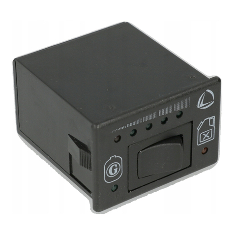
Landi Renzo LAMBDA CONTROL SYSTEM/2 Guide

LANDI RENZO S.p.A. - Via Fratelli Cervi 75/2 - 42100 Reggio Emilia - ITALY
Tel. +39/(0)522/382.678 - Fax +39/(0)522/382.906
GB
MANUALE INSTALLAZIONE E REGOLAZIONE pag. 6
MANUEL AND ADJUSTMENT MANUAL page 20
INSTALLATION AND ADJUSTMENT MANUAL page 13
I
F
EGUIA INSTALLACIONY REGULACION page 27
LAMBDA CONTROL SYSTEM/2
190177440/1

Technical Drawings
SchemiTecnici SchémasTechniques
EsquemaTécnicos
LANDI RENZO S.p.A.
Manuale di installazione e regolazione Lambda Control System/2
2/38
Fig. 1

Technical Drawings
SchemiTecnici EsquemaTécnicos
SchémasTechniques
LANDI RENZO S.p.A.
Manuale di installazione e regolazione Lambda Control System/2
3/38
Fig. 2

Technical Drawings
SchemiTecnici SchémasTechniques
EsquemaTécnicos
LANDI RENZO S.p.A.
Manuale di installazione e regolazione Lambda Control System/2
4/38
Fig. 4Fig. 3
Fig. 5
Fig. 6 Fig. 7

Technical Drawings
SchemiTecnici EsquemaTécnicos
SchémasTechniques
LANDI RENZO S.p.A.
Manuale di installazione e regolazione Lambda Control System/2
5/38
Fig. 8
Fig. 9
Fig. 10

Lambda Control System/2
LANDI RENZO S.p.A.
Manuale di installazione e regolazione Lambda Control System/2
6/38
Lambda Control System/2 è un sistema elettroni-
coautoregistranteper la gestionedell’alimentazio-
ne a gas (Gpl o Metano) di veicoli dotati di sonda
lambda e marmitta catalitica: non richiede
regolazioni manuali ed ha la capacità di adattarsi
automaticamentealle differenticondizioni ambien-
tali e di utilizzo dei veicoli, assicurando una carbu-
razione ottimale in termini di guidabilità, consumi
ed emissioni.
LCS/2gestisce elettronicamente la regolazionedel
flusso di gas consentendo al fattore lambda di rag-
giungere il valore richiesto a tutti i regimi grazie a
2 attuatori elettromeccanici. Un attuatore è instal-
lato tra riduttore e miscelatore e dosa la quantità
di gas ai medi e alti regimi (att-Max), mentre il se-
condo attuatore incluso nel riduttore di pressione
regola il flusso di gas ottimale per il funzionamen-
to del motore al minimo (att-min), mantenendolo
stabile anche in presenza di servizi quali condi-
zionatore, servosterzo etc…
1. SPECIFICHETECNICHE
1.1 COMPUTER LCS/2
Caratteristiche elettriche:
- Tensione di lavoro: 12V (-20% / +30%)
- Corrente massima assorbita durante il funziona-
mento: 0,6A
- Corrente massima applicabile al relè per interru-
zione iniezione benzina (fili gialli): 6,5A
- Correntemassimaerogabileperdispositividi con-
trollo gas (fili blu): 6,5A
- Grado di protezione da polvere ed acqua: IP65
Funzioni programmabili:
- Numero cilindri / tipo accensione
- Tipo segnale giri motore
- Tipo commutazione automatica benzina/gas
- Temperatura commutazione benzina/gas
(opzionale)
- Numero giri per commutazione automatica
- Tempo sovrapposizione carburanti durante
commutazione automatica
- Tipo TPS (sensore di posizione farfalla)
- Tipo sensore livello gas
- Tipo sonda lambda
- Ritardo lettura sonda lambda
- Tipo emulazione sonda lambda
- Opzione massima apertura farfalla in fase di
accelerazione
- Minima / massima apertura attuatore
- Opzione cut-off
- Opzione default fisso
- Reset memoria
1.2 ATTUATORE ELETTROMECCANICO
LINEARE
Caratteristiche elettriche:
- Tensione di lavoro: 12V
- Corrente assorbita: 150mA
- Potenza nominale: 2W
- Temperatura di funzionamento: -20°C / +120°C
- Grado di protezione da polvere ed acqua: IP65
2. FUNZIONI DEL SISTEMA LCS/2
Il sistema viene installato con i seguenti riduttori
di pressione GPL e metano
LANDI RENZO
: SE
81 con step-motor, TN1/B con step-motor.
Ilcomputer LCS/2 elabora i segnaliprovenientidal-
la sonda lambda, dall’accensione, dal sensore po-
sizione farfalla d’accelerazione TPS e contiene in
memoria un valore di tensione della sonda lambda
corrispondente alla miscela stechiometrica, che
deveesseremantenutaper ogni condizione di fun-
zionamento del motore.
La sonda lambda posta nel collettore di scarico
indica il rapporto di miscela ed in ogni istante invia
un valore di tensione al computer LCS/2, il quale
verifica sela miscela écorretta confrontandolo con
il valore posto in memoria; in caso di differenza il
computer pilota gli attuatori elettromeccanici Line-
ari variando opportunamente la portata di gas fino
a quando la miscela rientra nei parametri lambda.
Le funzioni principali del Lambda Control System/
2 sono le seguenti:
Controllo e gestione della carburazione durante
il funzionamento a gas;
Avviamento a benzina con commutazione auto-
matica del carburante;
Possibilità dipartenzain emergenza agasagen-
do semplicemente sul commutatore;
Dispositivodi sicurezza cheinterrompe l’alimen-
tazione delle elettrovalvole gas in caso di spe-
gnimento anche accidentale del motore;
Relè incorporato per l’interruzione dell’iniezio-
ne benzina con ritorno automatico al funziona-
mento a benzina in caso di avaria del sistema
LCS/2;
Funzione di ‘Start-Petrol’: gli attuatori elettro-
meccanici lineari chiudono il condotto del gas
durante il funzionamento a benzina ed a motore
spento;
Sistema di dialogo (con presa diagnostica) tra-
mite Tester-Programmatore V05 oppure Kit In-

Installazione
LANDI RENZO S.p.A.
Manuale di installazione e regolazione Lambda Control System/2
7/38
terfacciaV05 con software dedicato ed interfac-
cia seriale per personal computer.
LEGENDA (Fig. 1 Gpl; Fig. 2 Metano)
Il sistema è costituito dai seguenti elementi:
A) Computer LCS/2.
B) Attuatore elettromeccanico lineare
C) Commutatore/indicatore LCS/2.
D) Cablaggi per il collegamento del computer
LCS/2 ai relativi dispositivi.
E) Connettore per programmazione e diagnosi.
Gli altri elementi rappresentati nello schema
sono i seguenti:
F) Tester Programmatore V05 (versione V1).
G) Personal computer con Kit Interfaccia V05
(in alternativa al Tester Programmatore V05).
H) TPS (Sensore posizione farfalla).
I) Iniettori benzina.
L) Sonda Lambda.
M) Bobina di accensione.
N) Batteria.
O) Riduttore di pressione con attuatore
elettromeccanico lineare per il minimo.
P) Elettrovalvola gas.
Q) Sensore livello gas.
R) Sensore di temperatura; *componente
opzionale, fornito separatamente da LCS/2.
Gli schemi rappresentati in Fig.1 e 2 relativamen-
te all’impianto Gpl e Metano sono generici; per le
specifiche riguardanti i collegamenti elettrici, ve-
dere il paragrafo 6.
3. INSTALLAZIONE COMPUTER LCS/2
(Fig. 3)
Il computer deve essere fissato alla carrozzeria
del veicolo all’interno del vano motore secondo le
seguenti indicazioni:
Togliere i fusibili posti sul cablaggio prima di pro-
cedereall’installazione dei componentie reinserirli
ad installazione ultimata;
Il computer dovrà essere posizionato lontano da
fonti di calore (es.: collettore di scarico, radiatori,
ecc.), al riparo da spruzzi d’acqua e lontano dai
cavi alta tensione dell’accensione;
Il lato dei connettori del computer deve essere ri-
volto verso il basso per evitare che eventuali infil-
trazioni di acqua penetrino all’interno del compu-
ter.
4. INSTALLAZIONE ATTUATORE
ELETTROMECCANICO LINEARE (Fig.4)
4.1 ATTUATORE MINIMO REGIME (ATT-
MIN)
Il riduttore con attuatore elettromeccanico lineare
deve essere posizionato parallelamente al senso
di marcia del veicolo.
Inserire lo spinotto maschio, contrassegnato dal
terminale di colore ROSSO proveniente dal com-
puter LCS/2 al connettore presente sull’attuatore
Per maggiori chiarimenti consultare il manuale di
installazione stesso.
4.2 ATTUATORE MEDI E ALTI REGIMI (ATT-
MAX)
L’attuatore elettromeccanico lineare deve essere
installato preferibilmente all’ingresso del
miscelatore (al fine di ottimizzare la funzione di
cut-off) oppure, in alternativa, lungo il tubo di ali-
mentazione gas o sull’uscita gas del riduttore.
Inserire lo spinotto maschio proveniente dal com-
puter LCS/2 al connettore presente sull’attuatore
elettromeccanico lineare.
IMPORTANTE: non posizionare mai l’attuatore
elettromeccanico lineare con il motorino passo-
passo rivolto verso il basso od in modo che even-
tuali depositi di olio possano penetrare all’interno
del meccanismo.
5. INSTALLAZIONE E FUNZIONAMENTO
COMMUTATORE/INDICATORE LCS/2
(Fig. 5)
Installare il commutatore/indicatore LCS/2 nel cru-
scotto del veicolo secondo le seguenti modalità:
inserire il commutatore/indicatore LCS/2 in un foro
inutilizzato di dimensioni idonee già presente nel
cruscotto del veicolo;
inserire il commutatore/indicatore LCS/2 nel cru-
scotto del veicolo dopo aver ricavato tramite l’ap-
posito tranciante per commutatore
LANDI REN-
ZO
un foro rettangolare di dimensioni idonee (cir-
ca 25x38 mm);
posizionare il commutatore/indicatore LCS/2 nel
cruscotto del veicolo utilizzando il supporto ester-
no fornito in dotazione.
5.1 SPECIFICHE FUNZIONAMENTO
COMMUTATORE/INDICATORE LCS/2
A) selettore gas/benzina
a 2 posizioni con indicazione carburante in uso
tramite i due led luminosi (B) e (D);
B) led verde
acceso costantemente: indica il regolare funzio-
namento a gas;

Installazione
LANDI RENZO S.p.A.
Manuale di installazione e regolazione Lambda Control System/2
8/38
lampeggio rapido: indica lo stato di attesa della
commutazione automatica a gas in fase di av-
viamento (che avviene sempre a benzina);
lampeggio lento: indica il malfunzionamento del
sistema LCS/2 durante l’utilizzo a gas.
C) led giallo
acceso costantemente: indica il funzionamento
a benzina.
D) serie led
indicano il livello di gas (suddiviso in quarti) pre-
sente nel serbatoio;il led rosso segnala la riser-
va.
E) connettore
collega il commutatore al cablaggio proveniente
dal computer LCS/2.
5.2 PARTENZA IN EMERGENZA A GAS
CON COMMUTATORE/INDICATORE
LCS/2
Nel caso in cui sopravvengano problemi in fase di
avviamento a benzina (es.rottura pompa benzina,
ecc.), è possibile avviare il motore direttamente a
gas seguendo le sottoindicate istruzioni:
Girare la chiave di accensione dell’auto ed ac-
cendere il quadro;
Portare il commutatore (A) in posizione benzina
eriportarlo in posizionegassenzaeffettuarel’av-
viamento;
A questo punto il led verde (B) rimane acceso
costantemente;
Effettuare l’avviamento (senza spegnere il qua-
dro). In questa condizione il veicolo parte diret-
tamente a gas.
6. COLLEGAMENTI ELETTRICI LCS/2
Effettuare tutti i collegamenti sottoindicati con sal-
dature a stagno isolando i fili in modo adeguato.
6.1 FILI ROSSO-NERO E NERO (part.N Fig.
1 e 2) ALIMENTAZIONE COMPUTER
LCS/2
Per fornire in modo continuo l’alimentazione al si-
stema, effettuare i seguenti collegamenti del ca-
blaggio LCS/2:
- filo rosso-nero: collegato al positivo batteria
- filo nero: collegato al negativo batteria
Nel caso in cui il veicolo sia provvisto di batteria
nel vano bagagliaio, collegare il filo rosso-nero al
polo positivo che si trova nel vano motore e colle-
gare il filo nero ad un punto di massa comune ori-
ginale dell’impianto elettrico dell’auto (es. massa
del computer benzina o massa di altri dispositivi
come ABS, idroguida, ecc.).
6.2 FILI GRIGIO E VIOLA COLLEGAMENTO
SONDA LAMBDA
Il collegamento della sonda lambda al cablaggio
LCS/2 (Fig. 6) viene generalmente effettuato tra-
mite l’interruzione del filo del segnale lambda ed il
collegamento dei due capi ottenuti ai rispettivi fili
grigio e viola del computer LCS/2.Su speficici mo-
delli di auto può essere invece necessario colle-
gare solo il filo viola del computer LCS/2 senza
interrompere il filo della sonda, mentre il filo grigio
deve essere adeguatamente isolato. Le modalità
di collegamente della sonda lambda al computer
sonoriportate caso percaso nelle SCHEDEAUTO
del Servizio Assistenza Tecnica
LANDI RENZO
.
Al fine di facilitare l’individuazione del filo del se-
gnale lambda, qui di seguito sono elencate le più
comuni tipologie di sonda lambda:
SONDA
LAMBDA
AD
1
FILO
: individuare il filo che pro-
viene dalla sonda lambda e giunge al computer
benzina (Fig. 6A);
SONDA
LAMBDA
A
2
FILI
:individuare il filo del segna-
le lambda utilizzando un tester multimetro;su tale
filo la tensione rispetto alla massa varia da 0÷1V,
da 0.8÷1.6V oppure da 0÷5V;
SONDA
LAMBDA
A
3
FILI
:individuare il filo del segna-
le lambda come da punto precedente.Gli altri due
fili sono utilizzati per il riscaldamento della sonda
lambda: uno presenta una tensione di +12V e l’al-
tro è un negativo (Fig. 6B);
SONDA
LAMBDA
A
4
FILI
:
individuare il filo del segna-
le lambda come da punto precedente.Altri due fili
sono utilizzati per il riscaldamento della sonda
lambda (vedi punto precedente), mentre un filo è il
negativodelsegnaledella sonda lambda(Fig.6C);
6.3 FILO BLU-GIALLO COLLEGAMENTO AL
SEGNALE DELTPS
Il segnale del TPS indica al computer benzina in
quale posizione si trova la farfalla di accelerazio-
ne. Il collegamento del TPS al cablaggio LCS/2
viene effettuato secondo le seguenti modalità:
TPS proporzionale (Fig. 7A)
:
il segnale in uscita
da questo sensore ha una tensione che varia pro-
porzionalmente rispetto alla posizione della farfal-
la. Su questo tipo di sensore sono presenti 3 fili:
- un filo ha una tensione di alimentazione di +5V
(a quadro inserito);
- un filo è collegato al negativo batteria;
- un filo è il segnale in uscita delTPS e deve esse-
re collegato al filo blu-giallo del cablaggio LCS/2.

Installazione
LANDI RENZO S.p.A.
Manuale di installazione e regolazione Lambda Control System/2
9/38
La tensione all’estremità di questo filo varia ri-
spetto alla massa da 0 a 5V.
TPS di tipo “switch” (Fig. 7B)
:
i fili presenti su
questo sensore sono simili a quelli presenti su di un
TPS proporzionale come sopra descritto.Il segnale
in uscita da questoTPS presenta solamente 2 con-
dizioni:0Volt a farfalla chiusa, 12 Volt con farfalla in
condizione di fuori minimo, o viceversa.Identificare
il filo che costituisce il segnale in uscita del TPS
con l’impiego di un tester multimetro (assicurando-
si di effettuare le misure riferite a massa) e colle-
garlo al filo blu-giallo del cablaggio LCS/2.
6.4 FILO MARRONE (part. M Fig. 1e 2)
COLLEGAMENTO AL SEGNALE
NUMERO GIRI MOTORE (RPM)
Collegare il filo marrone del cablaggio LCS/2 al
negativo della bobina di accensione o, in alternati-
va, al filo del contagiri del veicolo.
6.5 FILO ROSSO COLLEGAMENTO 12V
SOTTOCHIAVE
Collegare il filo rosso del cablaggio LCS/2 ad un
dispositivo sottochiave come ad esempio il positi-
vo della bobina di accensione oppure ad un altro
filo che fornisca la tensione di 12V a quadro inse-
rito (part. M Fig. 1e 2).
6.6 FILI BIANCO E VERDE COLLEGAMEN-
TO AL SENSORE LIVELLO GAS
Il computer LCS/2 può essere abbinato a diversi
sensori livello gas in commercio secondo le se-
guenti modalità (Fig. 8):
Sensore Gpl/Metano tipo
LANDI RENZO
: colle-
gare il filo bianco del cablaggio LCS/2 al filo bian-
co del sensore livello gas e non collegare il filo
verde (il cui estremo dovrà essere isolato).
Sensore tipo A.E.B.: collegare i fili verde e bian-
codel cablaggio LCS/2 airispettivi filiverdeebian-
co del sensore livello gas.
Sensore tipo 0-90 ΩΩ
ΩΩ
Ω: collegare entrambi i fili ver-
de e bianco del cablaggio LCS/2 al filo del senso-
re livello gas
6.7 FILI GIALLI DISINSERIMENTO DEGLI
INIETTORI
Ifili gialli delcablaggioLCS/2sonocollegati ai con-
tatti di un relè normalmente chiuso.
La corrente massima applicabile come carico con-
tinuo è di 6,5A.
Durante il funzionamento a gas, (Fig.9A) i contatti
del relè si aprono impedendo agli iniettori benzina
di funzionare, mentre quando il motore è alimen-
tato a benzina, i contatti restano chiusi.
Impostare il computer LCS/2 alla voce‘TEMPO DI
SOVRAPPOSIZIONE’ il tempo desiderato (in secon-
di) di ritardo dell’apertura dei contatti in modo da
avere un’adeguata sovrapposizione dei carburanti
in fase di commutazione da benzina a gas.
Nel caso in cui, per disinserire gli iniettori, si im-
pieghi un emulatore elettronico (Fig. 9B) e sia ne-
cessario impostare un determinato ritardo per re-
golare la sovrapposizione dei carburanti, collega-
re un’estremità dei fili gialli del cablaggio LCS/2 a
massa e l’altra estremità alla apposita presa
sull’emulatore elettronico.
NOTA: in caso di un eventuale malfunzionamento
del sistema LCS/2 come l’apertura dei contatti del
fusibili il relè che cortocircutia i fili gialli si troverà
nella posizione di contatti chiusi ed il sistema di
disinserimento degli iniettori sarà disabilitato per-
mettendo al motore di funzionare a benzina.
6.8 FILO BLU ALIMENTAZIONE
DISPOSITIVI GAS
Il filo blu fornisce una tensione di +12V durante il
funzionamentoagas.Vieneimpieagata per coman-
dare l’elettrovalvola che controlla il flusso di com-
bustibile proveniente dal serbatoio gas e alimen-
tare gli eventuali emulatori e variatori di anticipo
(part. P Fig 1 e 2).
6.9 COLLEGAMENTO ATTUATORI
ELETTROMECCANICI LINEARI
Il connettore che presenta nella parte terminale la
guaina di colore ROSSO deve essere collegato
all’attuatore elettromeccanico lineare presente sul
riduttore (SE81 step-motor part. O Fig 1.;TN1B
step-motor part. O Fig. 2).
Il connettore non provvisto di nessun contrasse-
gno deve essere collegato all’attuatore
elettromeccanico lineare installato tra l’uscita gas
del riduttore e il miscelatore (part. B Fig. 1 e 2).
6.10 FILO ARANCIONE COLLEGAMENTO
SENSORE DITEMPERATURA
Il filo ARANCIONE deve essere collegato al sen-
sore di temperatura (dispositivo opzionale cod.
203076001) che si può installare sui riduttori di
pressione SE81, TN1/B. Questo componente sé
installato consente di impiegare la funzione TEM-
PERATURA PER CAMBIO, che permette di eseguire
il passaggio da benzina a gas solo dopo aver rag-
giunto la temperatura del riduttore che si è impo-
stata.
L’installazione di tale componente deve essere
eseguita a motore spento e con quadro

Installazione
LANDI RENZO S.p.A.
Manuale di installazione e regolazione Lambda Control System/2
10/38
disinserito.
Per l’installazione (Fig. 10) occorre sostituire il
tappo(A), posto aldi sotto delregistro della sen-
sibilità (B), con il sensore di temperatura (D) in-
terponendo la rondella (C).
Collegare uno dei fili arancioni al filo arancione
presente sul cablaggio del computer LCS/2 e
l’altro filo a massa (part S Fig 1 e 2).
7. FUNZIONAMENTO DI LCS/2
Le funzioni programmabili di LCS/2 possono es-
sere modificate solamente tramite l’apposito Te-
ster ProgrammatoreV05 o personal computer con
Kit Interfaccia V05 e relativo software dedicato.
ATTENZIONE: Per poter programmare il compu-
ter LCS/2 occorre impiegare un Tester Program-
matore aggiornato alla versione V1.La pagina del
“MENU PRINCIPALE”delTester Programmatoredeve
presentare la scirtta V1.
Anche quando il computer LCS/2 non è alimenta-
to (es. batteria staccata) le funzioni immesse re-
stano in memoria.
Per maggiori dettagli fare riferimento al ‘Manuale
di istruzioni Tester Programmatore V05’.
7.1 DATIVISUALIZZATI
Tramite il Tester Programmatore V05 (o personal
computer con Kit Interfaccia V05 installato
)
si
visualizzano i seguenti dati:
Nella prima pagina:
ATT:indica (in numerodipassi)la posizione intem-
po reale dell’attuatore elettromeccanico lineare
medi è alti regimi.
DEF: indica (in numero di passi) la posizione di
default acquisita (valore standard) dell’attuatore
elettromeccanico lineare medi è alti regimi.
GIRI: indica (in rpm) il numero di giri del motore in
tempo reale.
TPS: indica (in volt) la posizione del sensore posi-
zione farfalla di accelerazione.
][]]:indicano se si è in fase di minimo, di velocità
di crociera o di massima apertura farfalla di acce-
lerazione.
R ]]][]]] M: indicano se si è in fase di miscela
povera o ricca.
Nella seconda pagina:
att*: indica (in numero di passi) la posizione in
tempo reale dell’attuatore elettromeccanico linea-
re per il minimo.
def*: indica (in numero di passi) la posizione di
default acquisita (valore standard) dell’attuatore
elettromeccanico lineare per il minimo.
GIRI: indica (in rpm) il numero di giri del motore in
tempo reale.
TPS: indica (in volt) la posizione del sensore posi-
zione farfalla di accelerazione.
m [] M: indica se il regime del motore è in posizio-
ne di minimo (m [] M) o fuoriminimo (m ][ M).
R ]]][]]] M: indicano se si è in fase di miscela
povera o ricca.
Con il computer LCS/2 nuovo o appena resettato
laposizioneDEF didefaultdell’attuatoreelettromec-
canico lineare è di 100 passi
.
La posizione del minimo TPS e la posizione di
default dell’attuatore dei medi e alti regimi e del-
l’attuatore e del minimo vengono acquisite ad ogni
accensione del sistema; l’ultimo default acquisito
viene utilizzato come posizione di partenza.
NOTA: L’attuatore elettromeccanico lineare dei
medi e alti regimi viene indicato sul display del
Tester ProgrammatoreV05 con la dicitura att-Max;
L’attuatoreelettromeccanico lineare delminimo re-
gime viene indicato con la dicitura att-min.
7.2 FUNZIONI PROGRAMMABILI DI LCS/2
Nel prospetto sotto riportato vengono indicate le funzioni programmabili di LCS/2 con il relativo menu e
sotto-menu di programmazione in cui sono evidenziati in carattere neretto i parametri standard impo-
stati con computer nuovo o resettato.
Numero cilindri tipo di accensione ................................... 4,5,6,8 cilindri, bibobina, monobobina
Segnale RPM........................................................................................ segnale debole, standard
Cambio benzina-gas............................................ accelerazione, decelerazione, partenza a gas
-Tempo di cicchetto
1...............................................................................................................................................
(0,8 sec.) 0,0-5,0 sec.
-Temperatura per cambio (opzionale)
2............................................................................................................
(30 °C), 20-40 °C
RPM per cambio2..................................................................................................................................... (2000 RPM), 400-9000 RPM
-Tempo di sovrapposizione carburanti
2................................................................................................
(0.400 sec.), 0-1 sec.
TPS (sensore posizione farfalla) .......................... 0-5V, 5-0V lineare, 0-12V switch,TPS adapter
Sensore livello gas ......................................................................
Landi Renzo
, A.E.B., 0-90 ohm
Sonda lambda........................................................................................ 0-1V, 0-5V, 5-0V, 0.8-1.6V

Regolazione
LANDI RENZO S.p.A.
Manuale di installazione e regolazione Lambda Control System/2
11/38
Ritardo lettura sonda ....................................................................................(5 sec,)., 0-1250 sec.
Emulazione .............................................................................. Onda quadra, sconnessa, massa
-Tempo di alto
3..................................................................................................................................................................
(0.36 sec.), 0-5 sec.
-Tempo di basso
3..............................................................................................................................................................
(0.36 sec.),0-5 sec.
-Tempo di sonda sconnessa
3......................................................................................................................
(0.00 sec.), 0-654 sec.
-Numero di onde dopo la sconnessione
4.....................................................................................................................................
0-255
Salto att-Max in accelerazione ................................................................... abilitata, non abilitata
-Posizione salto
5...................................................................................................................................................................................
20-240 passi
-TPS per salto
5.......................................................................................................................................................................................................
1.4-5V
Massima apertura att-Max ....................................................................(240 passi), 20-240 passi
TPS per rilascio limitazioni ..........................................................................................(5.0V), 0-5V
Minima apertura att-Max .........................................................................(20 passi), 20-240 passi
RPM per att-min................................................................................ (1100 RPM), 600-2000 RPM
Max apertura att-min .............................................................................(240 passi), 20-160 passi
Min apertura att-min ................................................................................(20 passi), 20-160 passi
Cut-off ......................................................................................................... abilitata, non abilitata
-RPM minimi per cut-off
6................................................................................................................................................
1000-4000 g/min.
-Posizione att-Max in cut-off
6.................................................................................................................................................
20-240 passi
Incremento att-Max in accelerazione ......................................................... abilitata, non abilitata
-Variazione TPS per incremento
7...................................................................................................................................................
0.1-1.5V
-N° passi di incremento
7....................................................................................................................................................................
0-80 passi
Default fisso att-Max................................................................................... abilitata, non abilitata
-Valore del default fisso att-Max
8.......................................................................................................................................
20-240 passi
Default fisso att-min.................................................................................... abilitata, non abilitata
-Valore del default fisso att-min9......................................................................................................................................... 20-160 passi
1.Il parametro viene visualizzato se cambio benzina-gas è impostato su partenza a gas.
2.Il parametro viene visualizzato se cambio benzina-gas è impostato su accelerazione o decelerazio-
ne.
3.Il parametro viene visualizzato se il tipo di emulazione è impostato su onda quadra.
4.Il parametro viene visualizzato se il tempo di sonda sconnessa è maggiore di 0.
5.Il parametro viene visualizzato se l’opzione di affondata è abilitata.
6.Il parametro viene visualizzato se l’opzione cut-off è abilitata.
7.Il parametro viene visualizzato se l’opzione incremento att-Max in accelerazione è abilitata.
8.Il parametro viene visualizzato se l’opzione default fisso att-Max è abilitata.
9.Il parametro viene visualizzato se l’opzione default fisso att-min è abilitata.
7.3 NOTE RELATIVE ALLA PROGRAMMA-
ZIONE DI LCS/2
L’emulazione standard della sonda lambda è im-
postata TIPO DI EMULAZIONE ONDA QUADRA.
Questo tipo di emulazione viene impiegato per la
maggior parte delle auto e deve essere cambiato
solo se prescritto dal MANUALE TECNICO LAN-
DI RENZO SCHEDE AUTO MT012.
L’emulazione della sonda lambda per veicoli dotati
di
Monoiniettore Bosch
(per i quali si imposta il
parametro TIPO DI TPS MONO BOSCH) viene
effettuata programmando TIPO DI EMULAZIONE
MASSA.In questi veicoli si collega il filo giallo-blu
del cablaggio LCS/2 al filo n.2 (anziché al filo n.4)
del connettore TPS posto a fianco del corpo
farfallato.
Nel caso in cui si presentino messaggi di errore
sul display del Tester Programmatore (o del per-
sonal computer nel caso si utilizzi il Kit Interfaccia
V05) come ad esempio ‘PREMERE OK PER
RESETTAMENTO TESTER’, oppure nel caso in cui
non si riesca a dialogare con il computer LCS/2,
occorrerà togliere entrambi i fusibili presenti sul
cablaggio del computer e reinserirli dopo 20”; in
questo modo il microcontrollore presente nel com-
puter LCS/2 fa un reset del programma.
Dopodiché si potrà procedere con una nuova pro-
grammazione.

Regolazione
LANDI RENZO S.p.A.
Manuale di installazione e regolazione Lambda Control System/2
12/38
7.4 DIAGNOSI ANOMALIE DI FUNZIONA-
MENTO
Il commutatore/Indicatore LCS/2 è in grado di
evidenziare all’installatore oppure all’utente alcu-
ne condizioni di errore.
Qualora durante la marcia con commutatore in po-
sizione gas il LED verde (lettera B Fig. 5) inizi a
lampeggiare lentamente, significa che si è verifi-
cata una delle seguenti condizione di errore:
la sonda lambda non funziona;
la sonda lambda rileva la miscela ricca per trop-
po tempo;
la sonda lambda rileva la miscela povera per
troppo tempo;
Tali condizioni di errore, anche se non più segna-
late alle successive accensioni del veicolo, ven-
gono registrate nella memoria dell’LCS/2 in modo
permanente.
Con l’impiego dell’appositoTester Programmatore
o Kit Interfaccia V05 si visualizza (alla voce ‘DIA-
GNOSI’) il tipo di errore e, una volta effettuato l’in-
tervento risolutivo del problema, occorre cancel-
larlo dalla memoria.
8. REGOLAZIONE DEL COMPUTER LCS/2
8.1 PROCEDURA PER L’APPRENDIMENTO
DELLA CARBURAZIONE CON LCS/2
Per l’apprendimento della carburazione con LCS/
2 seguire le sottoindicate istruzioni:
1) Verificare con l’aiuto dello schema elettrico, re-
lativo all’auto, i collegamenti elettrici.
2) Inserire ifusibili suicablaggi(fusibilitolti in fase
di installazione di LCS/2).
3) Collegare il Tester ProgrammatoreV05 (oppure
il personal computer con Kit Interfaccia V05 in-
stallato) alla presa di diagnosi e programmazio-
ne situata sul cablaggio del computer LCS/2.
4) Tramite ilTester ProgrammatoreV05 (oppure il
personal computer) adeguare opzione per op-
zione i parametri del computer LCS/2 alle spe-
cifiche del veicolo (vedi par. 7.2).
5) Verificare di aver memorizzato nel computer
LCS/2 le opzioni esattamente corrispondenti
alle caratteristiche del veicolo. In caso contra-
rio, effettuare il reset della memoria del com-
puter LCS/2 e verificare che assuma i valori
standard evidenziati in neretto nel paragrafo
7.2;adeguare successivamente un’altra volta i
parametri del computer LCS/2 alle specifiche
del veicolo e ripetere la verifica.
6) Avviare il motore con il commutatore/indicato-
re LCS/2 in posizione benzina ed attendere
qualche minuto per permettere alla sonda
lambda di scaldarsi.
7) Entrare nella ‘pagina’ VISUALIZZA del Tester
Programmatore (o del personal computer).
8) Ad auto ferma, commutare a gas ed effettuare
una serie di accelerazioni e decelerazioni gra-
duali, intervallate di qualche secondo; in que-
sto modo il computer LCS/2 apprenderà la po-
sizione del minimo TPS.
9) A questo punto si regola la portata di gas ai
mediealtiregimi:portareilmotorea circa 3.500
giri/min. (][]], ]][]) fino ad apprendimento
del valore di default (la voce DEF visualizzata
sul display del Tester Programmatore cambie-
rà di valore). Inoltre l’indicatore lambda, pre-
sente nella pagina di visualizzazione dati, ini-
zierà ad oscillare indicando un corretto funzio-
namento del sistema durante il funzionamento
a pieno regime.
10)Portare lentamente il regime del motore al mi-
nimo; Visualizzare la pagina relativa all’attua-
tore del minimo, verificare che il regime del
motore sia nella condizione di minimo (m []
M), lasciarlo in questa posizione per 2 min.Alla
fine del sopraindicato intervallo di tempo si
vedrà l’indicatore lambdaoscillare (lavoce DEF
visualizzata sul display delTester Programma-
tore cambierà di valore), indicando che la car-
burazione ottimale al minimo regime del moto-
re e stata raggiunta. Il computer LCS/2 atten-
de 1 min. quando il motore è al regime minimo
prima di modificare il default del minimo.
11)Verificare che a tutti i regimi oscillino regolar-
mente i LED della scala lambda che indicano
la carburazione.
12)Controllareconl’analizzatoregasdiscarico che
il valore lambda oscilli intorno al valore 1,000 e
che i valori di CO, HC e CO2siano come da
tabelle riportate nelle istruzioni di installazione
e regolazione dei riduttori
LANDI RENZO
.
13)Acquisiti il default del’attuatore del minimo re-
gime (att-min) e dell’attuatore dei medi e alti
regimi (att-Max), effettuare un test su strada.
Dati, descrizioni e illustrazioni hanno solo valore
indicativo e LANDI RENZO S.p.A.si riserva il dirit-
to di apportare, a suo criterio e senza preavviso,
migliorie o modifiche.
Il riduttore presente nell’immagine di copertina è
fornito separatamente da LCS/2.

Lambda Control System/2
LANDI RENZO S.p.A.
Installation and adjustament manual Lambda Control System/2
13/38
LAMBDA CONTROL SYSTEM/2 is a self-adjust-
ingelectronic system to controlthegas supply (Lpg
or Cng) of vehicles equipped with a lambda sen-
sor and catalytic converter: it requires no manual
adjustments and can automatically adapt to the
different environmental conditions and use of the
vehicle so as to ensure optimum carburation in
terms of driving, consumption and emissions.
LCS/2 electronically controls the regulation of gas
flow enabling the lambda factor to reach the val-
ues required at all speeds thanks to 2 electro-me-
chanical actuators. One actuator is fitted between
the reducer and mixer and determines the quan-
tity of gas at medium and high speeds (att-Max),
while the second actuator of the pressure reducer
ensures the proper gas flow for engine operation
at low speed (att-min), also maintaining this stable
withrespectto accessorieslikeconditioners,power
steering, etc. when these are operating.
1. TECHNICAL SPECIFICATION
1.1 COMPUTER LCS/2
Electrical specifications:
- Power supply: 12V (-20% / +30%)
- Max. power absorption during operation: 0,6A
- Max. power applicable to the relay to interrupt
petrol injection (yellow wires): 6,5A
- Max. power output for gas control devices (blue
wires): 6,5A
- Water and dust protection level: IP65
Programmable functions
- Number of cylinders / type of ignition
- Type of engine rpm signal
- Type automatic petrol/gas change
- Petrol/gas switchover temperature (optional)
- Rpm number for automatic change
- Fuel overlapping time during automatic change
- TPS type (throttle position sensor)
- Gas level sensor type
- Type lambda sensor
- Lambda sensor reading delay
- Type of lambda sensor emulation
- Max. open throttle position during acceleration
- Min / max. actuator opening
- Cut-off option
- Fixed default option
- Memory resetting
1.2 LINEAR ELECTROMECHANICAL
ACTUATOR
Electrical specifications:
- Power supply: 12V
- Power absorption: 150mA
- Nominal power: 2W
- Operating temperature: -20°C / +120°C
- Water and dust protection level: IP65
2. LCS/2 FUNCTIONS
LCS/2 is used with following Lpg or Cng
LANDI
RENZO
SE 81 STEP MOTOR and TN1/B STEP
MOTOR.
The LCS/2 Computer processes the signals from
the lambda sensor, ignition, throttle position sen-
sor TPS and holds in memory a lambda sensor
tension value corresponding to the stoichiometric
mixture that needs to be maintained for every op-
erating condition of the engine.
The lambda sensor in the exhaust manifold indi-
cates the mixture ratio and at every moment sends
a value of voltage to the LCS/2 Computer which
checks whether the mixture is correct by compar-
ing it with the value set in memory; if there is a
difference, the computer will drive the Linear Elec-
tromechanical Actuator, suitably changing the rate
of flow of gas until the mixture comes back into the
lambda stoichiometric value.
The main functions of the LAMBDA CONTROL
SYSTEM/2 include:
control of carburation during gas operation;
petrol starting with automatic switch over to gas,
also in relation to the engine temperature;
possibility of emergency gas starting by simple
operation on the switch;
electronic safety device that cuts off gas sole-
noid valve supply in the event of the engine ac-
cidentally stalling;
built-in relay to cut off petrol injection with auto-
matic change over to petrol in case of LCS/2
damage;
Petrol-Start function:theLinear Electromechani-
cal Actuator closes the gas line while running
on petrol and when the engine is stopped.
interface system (using a diagnostic connector)
with a diagnostic and programming instrument
Programmer - Tester V05 or Interface Kit V05
with dedicated software and serial interface for
personal Computer.
LEGEND (Fig. 1 Lpg; Fig. 2 Cng)
The system consists of the following components:
A) Computer LCS/2
B) Linear Electromechanical Actuator

Installation
LANDI RENZO S.p.A.
Installation and adjustament manual Lambda Control System/2
14/38
C) Switch/Gauge LCS/2
D) Wiring harness to connect LCS/2 Com-
puter to relevant devices
E) Programming and diagnosis connector
F) Others elements represented in the diagram
are:
G) Programming Tester V05
Personal computer with Interface Kit V05 (in
alternative to Programming Tester V05)
H) TPS (Throttle position sensor)
I) Petrol injectors
L) Lambda sensor
M) Ignition coil
N) Battery
O) Gas solenoid
P) Pressure regulator
Q) Gas level sensor
R) Temperature sensor *(optional component
supplied separately from LCS/2)
The drawings shown in Fig. 1 and 2 concerning
the Lpg and Cng conversion system are indica-
tive; for specific situations concerning the electri-
cal connections, see paragraph 6.
3. INSTALLATION OF COMPUTER LCS/2
(Fig. 3)
The Computer must be attached to the car chas-
sis inside the engine compartment according fol-
lowing instructions:
- remove the fuses located on the wiring before
installing the parts and replace them once instal-
lation has been completed;
- positionthe Computer awayfromsourcesof heat
(exhaust header, radiators, etc.), protected by
water and away from ignition high voltage wires;
- position the Computer with the connector side
facing down to prevent any water droplets from
penetrating inside the control unit through the
connectors.
4. INSTALLATION OFTHE LINEAR
ELECTRO-MECHANICAL ACTUATOR
(Fig. 4)
4.1 LOW-SPEED ACTUATOR (ATT-MIN)
The reducer with linear electro-mechanical actua-
tor must be positioned parallel to the direction of
movement of the vehicle.
Fitthe male jack (markedby the REDterminalfrom
computer LCS/2) in the connector on the actuator.
For more details, refer to the STEP MOTOR re-
ducer installation instructions inside the reducer
pack.
4.2 MEDIUM-HIGH SPEED ACTUATOR
(ATT-MAX)
The Linear Electromechanical Actuator must be
installed preferably at the mixer inlet (in order to
optimisethecut-offfunction) or,in alternative,along
the gas hose or on the regulator outlet.
Insert the male pin coming from the LCS/2 com-
puter to the connector on the Actuator.
IMPORTANT:never position theLinear Electrome-
chanical Actuator with the motor facing down or in
such a way that oil deposits can penetrate inside
the motor.
5. INSTALLATION AND OPERATION OF
SWITCH / GAUGE LCS/2 (Fig. 5)
Installthe Switch /Gauge LCS/2 onthe dashboard
according following possibilities:
- insert the Switch / Gauge LCS/2 in an existing
hole with suitable dimensions;
- insertthe Switch /GaugeLCS/2in the dashboard
aftermakingarectangularhole (about 25x38 mm)
with the LANDI RENZO cutting device for
switches;
- position the Switch / Gauge LCS/2 in the dash-
board by using the external support provided.
5.1 SWITCH / GAUGE LCS/2 OPERATION
EXPLANATION
A) gas / petrol selector
with 2 position and indication of used fuel by
mean of 2 leds (B) and (C);
B) green led
turned on: indicates the car is regularly running
on gas;
rapid flashing: indicates the stand by for the au-
tomatic change over during the starting (that is
always on petrol);
slow flashing: indicates the malfunctioning of
LCS/2 during gas operation (see par. 5.3).
C) yellow led
turned on:indicates the car is running on petrol.
D) led series
indicates the level of gas (divided into fourths)
present in the tank: the red led indicates the car
is running on reserve.
E) connector
connect the switch to the wires coming from the
LCS/2 Computer.

Installation
LANDI RENZO S.p.A.
Installation and adjustament manual Lambda Control System/2
15/38
5.2 EMERGENCY STARTING ON GAS
WITH SWITCH / GAUGE LCS/2
In case of malfunctioning during the petrol starting
(ex. petrol pump damage, etc.), it is possible to
start directly on gas following listed instruction:
Turn the ignition key until the board is turned on;
Set the switch (A) to the petrol position and re-
turn it to the gas position without starting;
Now the green led (B) turns on;
Start the vehicle (without turn off the board). In
this condition the vehicle begin running directly
with gas.
6. LCS/2 ELECTRICAL CONNECTIONS
It is recommended to solder listed wire connec-
tions and insulate them properly.
6.1 RED-BLACK AND BLACK WIRES (lt. N
Fig. 1 and 2) COMPUTER LCS/2
POWER SUPPLY
To deliver a continuous power to the system, made
following connections of LCS/2 wiring:
- red-black wire: connect to the battery positive
- black wire: connect to the battery negative
In the case the vehicle has the battery in the lug-
gage compartment, connect the red-black wire to
the positive pole in the engine compartment and
the black wire to an original common earth of the
electric equipment of the vehicle (ex. earth of the
petrol computer or other devices such as ABS,
power steering, etc.)
6.2 GREY AND VIOLET WIRES (Fig. 6)
LAMBDA SENSOR CONNECTION
GREY AND VIOLET LEADS LAMBDA
PROBE CONNECTION
Connection of the lambda probe to the LCS/2 wir-
ing system (Fig.6) is normally done by cutting the
lambda signal wire and connecting the two ends
thus obtained to the respective grey and violet
leads of the LCS/2 computer. On certain car mod-
els, it may be necessary to connect just the violet
lead of the LCS/2 computer without cutting the
probe wire, while the grey lead must be properly
insulated. Instructions for connecting the lambda
probe to the computer are given, case by case, in
the CAR SHEETS provided by the LANDI RENZO
After-Sales Service.
In order to make the lambda signal wire easier to
find, below is a list of the most common types of
lambda probes:
Single-wire lambda probe: determine the wire
linking the lambda probe and the petrol computer
(Fig. 6A);
two-wire lambda probe: determine the lambda
signal wire using a multimeter tester; on this wire,
the voltage with respect to the mass varies from
0÷1V, from 0.8÷1.6V or from 0÷5V;
three-wire lambda probe: determine the lambda
signal wire as indicated above.The other two wires
are used to heat the lambda probe:one has a volt-
age of +12V and the other is negative (Fig. 6B);
four-wire lambda probe: determine the lambda
signal wire as indicated above.Another two wires
are used to heat the lambda probe (see previous
point), while one wire is the negative lead of the
lambda probe signal (Fig. 6C);
6.3 BLUE-YELLOW WIRE TPS SIGNAL
CONNECTION
The TPS signal communicates the position of the
acceleration throttle to the petrol computer. The
connection of theTPS to the LCS/2 wiring is made
according following instructions:
ProportionalTPS (Fig.7A): the output signal from
this sensor has a voltage that is proportional to
thethrottleposition.This type ofsensorhas3 wires:
- one has a power supply voltage of +5V, with the
instrument panel on;
- one is connected to the battery negative;
- one is the sensor output and must be connected
to the blue-yellow wire of the LCS/2.The voltage
at the ends of this wires, with respect to ground,
varies from 0 to 5V.
Switch typeTPS (Fig. 7B): the wires on this sen-
soraresimilartothose on a proportionalTPSabove
described.The output signal from this sensor has
only 2 conditions: 0 Volts with throttle closed and
12Volts with the throttle is in out of idling condition
or vice versa. Identify the wire that is the output
signal of TPS by means of a tester (making sure
that the measurements are performed with refer-
ence to ground) and connect the same to the blue-
yellow wire of the LCS/2.
6.4 BROWN WIRE ENGINE RPM SIGNAL
CONNECTION
Connect the brown wire of LCS/2 to the negative
ofthe ignition coilor,asan alternative, to the speed
indicator wire (lt. M Fig. 1 and 2).
6.5 RED WIRE 12V IGNITION KEY
CONNECTION
Connectthe red wireof LCS/2 toa keydevicesuch
as the positive of the ignition coil or to another wire

Installation
LANDI RENZO S.p.A.
Installation and adjustament manual Lambda Control System/2
16/38
that supplies 12V when the board is turned on (lt.
M Fig. 1 and 2).
6.6 WHITE AND GREEN WIRES
CONNECTION TO THE GAS LEVEL
SENSOR
The LCS/2 Computer operates with different gas
level sensors available on the market according
following instructions (Fig. 8):
LANDI RENZO type Lpg/Cng sensor: connect
the white wire of LCS/2 to the white wire of the gas
levelsensor;thegreenwire remains disconnected,
insulating its end.
A.E.B.type sensor:connectbothgreenand white
wires of LCS/2 to the respective green and white
wires of the gas level sensor.
0-90 ΩΩ
ΩΩ
Ωtype sensor:connectboth green andwhite
wires of LCS/2 to the gas level sensor wire.
6.7 YELLOW WIRES DISCONNECTING
THE INJECTORS
The yellow wires of LCS/2 are connected to the
contacts of a normally closed relay.During gas op-
eration, (Fig. 9A) the contacts of the relay open,
thus preventing the injectors from operating;when
the engine is fed with petrol, these contacts re-
main closed.
Set the LCS/2 Computer at the parameter ‘OVER-
LAP TIME’ preferable retard timing (in seconds) of
the contacts open in order to have a suitable fuel
overlapping during change from petrol to gas.The
maximum applicable current as a continuous load
is 6.5 A.
If an electronic emulator is used to disconnect the
injectors (Fig. 9B) and it is necessary to set a fuel
overlapping time, connect one end of the yellow
wires of LCS/2 to ground and the other to the spe-
cial connector on the electronic emulator.
NOTE: in the event of LCS/2 malfunction, the in-
jector switchoff system will be automatically disa-
bled to enable the engine to run on petrol.
6.8 GAS DEVICE FEED BLUE LEAD
The blue lead provides a voltage of +12V during
gas operation. It is used to command the solenoid
valve which controls the flow of gas from the tank
and power any emulators and spark advance con-
trols (part. P Fig 1 e 2).
6.9 LINEAR ELECTRO-MECHANICAL
ACTUATOR CONNECTION
The connector with the RED sheath on the end
must be connected to the linear electromechani-
cal slow-speed actuator (att-min) located on the
reducer (SE81 STEP MOTOR part O Fig 1.;TN1/
B STEP MOTOR part O Fig. 2).
The unmarked connector must be connected to
the linear electromechanical high-speed actuator
(att-Max) installed between the reducer gas outlet
and the mixer (part B Fig. 1 and 2).
6.10 ORANGE LEADTEMPERATURE
SENSOR CONNECTION
The ORANGE lead must be connected to the tem-
perature sensor (optional component code
203.076.001) which can be installed on the LPG
or CNG reg. STEP MOTOR. When installed, this
component allows programming the SWITCH TEM-
PERATURE function so as to set automatic switch
from petrol to gas only when the reducer has
reached the set temperature.
Installation of the temperature sensor must be
done with the engine off and panel disengaged.
To install (Fig. 10) replace the cap (A), under
the sensitivity register (B), with the temperature
sensor (D) also fitting washer (C).
Connect one of the orange leads of the tem-
perature sensor to the orange lead from the wir-
ing system of the LCS/2 computer and earth the
other lead (part S Fig 1 and 2).
7. OPERATION
The programmable functions of LCS/2 can be set
only by the Programmer Tester V05 or by a per-
sonal computer with Interface Kit V05 and dedi-
cated software.
Also when the LCS/2 is not fed (ex. battery dis-
connected), the memorised functions are stored.
For more details, see the ‘Instruction Manual Pro-
grammer Tester V05’.
IMPORTANT:Toprogram the LCS/2 computer,use
aProgrammer Tester updated toversion V1; make
sure the page of the “MAIN MENU” of the Pro-
grammer Tester indicates V1.
7.1 DATA DISPLAY
By the Programmer Tester V05 (or personal com-
puterwith InterfaceKitV05installed) followingdata
are displayed:
ACT: indicates (in number of steps) the actual po-
sition of the Linear Electromechanical Actuator
DEF: indicates (in number of steps) the acquired
defaultposition (standard value)oftheLinearElec-
tromechanical Actuator
RPM: indicates (in rpm) the actual number of revo-
lutions of the engine
TPS: indicates (in volt) the position of the throttle

Carburation learning procedure
LANDI RENZO S.p.A.
Installation and adjustament manual Lambda Control System/2
17/38
position sensor
]]][]]]: indicate if you are in an idling condition,
cruise condition or maximum open throttle condi-
tion
att*: indicates (in number of steps) the position
of the electromechanical linear slow-speed actua-
tor in real time.
def*: indicates (in number of steps) the acquired
default position (standard value) of the electrome-
chanical linear slow-speed actuator.
RPM: indicates the revolutions per minute of the
engine in real time.
TPS: indicates (in volts) the position of the accel-
eration throttle sensor.
m [] M: indicates whether engine speed is slow (m
[] M) or at runaway speed rate (m ][ M).
R ]]][]]] M: indicates mixture phase, poor or
rich mixture.
When the LCS/2 is new or just reset, the DEF de-
fault position of the electromechanical linear ac-
tuator is 100 steps
.
The TPS minimum position and the default posi-
tion of the medium and peak actuator speeds, of
the actuator and of slow speed are acquired every
time the system is switched on; the last acquired
default is used as departure position.
LAMBDA SENSOR LEARNING RANGE: indicate
if you are in a poor or rich mixture condition
With LCS/2 Computer new or resetted the ‘DEF’
position of the Linear Electromechanical Actuator
is 100 steps.
The minimum TPS position and the default posi-
tion of the Linear Electromechanical Actuator are
acquired at every ignition of the system; the last
acquired default is used as starting position.
NOTE: the electromechanicallinear actuator ofthe
medium and peak speeds is indicated on the dis-
play of the Programmer Tester V05 by the mes-
sage att-Max; the electromechanical linear slow
speed actuator is indicated by the message att-
min.
7.2 LCS/2 PROGRAMMABLE FUNCTIONS
Here below are indicated the programmable functions of LCS/2 with relevant programming menu and
options in which are pointed out in bold type the standard parameters settled with computer new or
resetted.
Number of cylinder / type of ignition:............................ double-coil, single-coil, 4/5/6/8 cylinders
Rpm signal ............................................................................................................. standard, weak
Petrol/gas automatic change .................................. in deceleration, in acceleration, gas starting
-Priming time
1...........................................................................................................................................................
(0,8 sec); 0,0 ÷ 5,0 sec.
-Temperature for change (optional)
2...............................................................................................................
(30°C); 20° ÷ 40°C
Rpm for automatic change2....................................................................................................... (2.000 rpm), 400 ÷ 9.000 rpm
-Fuel overlapping time during automatic change
2......................................
(0,400 sec.); 0,000 ÷ 1,000 sec.
Tps (throttle position sensor)Linear 0-5V, 5 - 0V;switch 0 - 12V,12 - 0V; mono bosch; tps adapter
Gas level sensor ...........................................................................
Landi renzo
, A.E.B., 0-90 ohm
Lambda sensor .................................... 0 - 1V; 0,8 - 1,6V; 0 - 5V ‘a’; 0 - 5V ‘b’; 5 - 0V ‘a’; 5 - 0V ‘b
Lambda sensor reading delay ...................................................................(5 sec.), 0 ÷ 1.250 sec.
Lambda sensor emulation ................................................... Square wave, disconnected, ground
-high time
3.........................................................................................................................................................................
(0,36 sec.), 0 ÷ 5 sec.
-Low time
3.........................................................................................................................................................................
(0,36 sec.), 0 ÷ 5 sec.
-Disconnected sensor time
3....................................................................................................................
(0,00 sec.), 0 ÷ 654 sec.
-Number of waves after disconnection
4....................................................................................................................................
0 ÷ 255
Actuator-max jump in acceleration................................................................ not enabled, enable
-Actuator-max position during jump
5........................................................................................................................
40 ÷ 240 steps
-Tps for jump
5..............................................................................................................................................................................
1,5 ÷ 5,0V (2,8V)
Actuator-max high position................................................................ (240 steps), 20 ÷ 240 steps
Tps to release limitation .....................................................................................(2,8V), 0,0 ÷ 5,0V
Actuator-max low position .................................................................. (20 steps ), 20 ÷ 240 steps
RPM reference act-min..................................................................... (1100 RPM), 600-2000 RPM
Act-min high position ........................................................................ (160 steps ), 20 ÷ 160 steps

Carburation learning procedure
LANDI RENZO S.p.A.
Installation and adjustament manual Lambda Control System/2
18/38
Act-min low position............................................................................. (20 steps ) 20 ÷ 160 steps
Cut-off option ............................................................................................... not enabled, enabled
-Minimum rpm for cut-off
6................................................................................................................................................
400 ÷ 9.000 rpm
-Actuator-max position for cut- off
6.................................................................................................................................
40 240 steps
Actuator-max increase in acceleration........................................................ not enabled, enabled
-TPS deviation for increase
7..........................................................................................................................................................
0,1 ÷ 1,5V
-Number steps for increase
7.....................................................................................................................................................
0 ÷ 30 steps
Actuator-max position for fixed default ........................................................ not enabled, enabled
-Fixed default act-max value
8................................................................................................................................................
20-160 steps
Actuator-max position for fixed default ........................................................ not enabled, enabled
-Fixed default act-min value
9..................................................................................................................................................
20-160 steps
Lcs/2 memory resetting ............................................................................................. ok to confirm
Allows to re-set the standard values (in bold type) of lcs/2 computer
1 The parameter is displayed if the petrol/gas automatic change is set on gas starting
2.The parameter is displayed if the petrol/gas automatic change is set on acceleration or deceleration.
3.The parameter is displayed if the type of emulation is set on SQUARE WAVE.
4.The parameter is displayed if the disconnected sensor time is greater than 0.
5.The parameter is displayed if the act-Max deviation in acceleration option is ENABLED.
6.The parameter is displayed if the Actuator-max increase in acceleration is ENABLED.
7.The parameter is displayed if the cut-off option is ENABLED.
8.The parameter is displayed if the act-Max fixed
default option is ENABLED.
9. The parameter is displayed if the act-min fixed
default option is ENABLED.
7.3 NOTES CONCERNINGTHE LCS/2
PROGRAMMATION
The standard emulation of the lambda sensor is
settled as TYPE OF LAMBDA SENSOR EMULATION
SQUARE WAVE. This kind of emulation is used for
the main part of the vehicles and must be changed
only if allowed from the TECHNICAL MANUAL
LANDI RENZO MT012.
The lambda sensor emulation of vehicles with
MonoinjectorBosch (forwhich the parameterTYPE
OF TPS MONO BOSCH) is made programming the
parameter TYPE OF EMULATION GROUND. On this
vehiclestheyellow-blue wire of LCS/2mustbecon-
nected to the wire n. 2 (and not to the wire n. 4) of
the TPS connector at side of the throttle body.
In the case some error messages are displayed
on the Programmer Tester V05 (or personal com-
puter with Interface KitV05) as for example‘OK TO
RESET TESTER’, or in the case it is not possible to
dialogue with LCS/2 Computer remove both fuses
from the computer wiring system and refit these
after 20”; this way, the microcontroller of the LCS/
2 computer will perform a program reset.
7.4 MALFUCNTIONING DIAGNOSIS
The Switch / Gauge LCS/2 is in the position to
point out to the installer or the driver some error
conditions.While the car is running on gas, if the
green led D (letter B Fig.5) begins flashing slowly,
this indicates that one of the following error condi-
tions has occurred:
lambda sensor is not working;
lambdasensordetectsa rich mixturefortoolong;
lambda sensor detects a lean mixture for too
long;
The type of error, even if no longer indicated the
next time the car is started, is permanently re-
corded in the memory of the LCS-A1 V05.Use the
ProgrammerTester V05 or the Interface KitV05 to
display the type of error and, once the problem
hasbeen solved,it can be cancelled frommemory.
8. CARBURATION LEARNING PROCEDU-
REWITH LCS/2
To learn the carburation with LCS/2 follow listed
instructions:
1) Makesure the electricalconnections of thegas
systemaremadeproperly according to thespe-
cific sheet of the MT012 CAR SHEET TECH-
NICAL MANUAL of the LANDI RENZO After-
Sales Service.
2) Replacethefuses on the wiring (fuses removed
during the installation of LCS/2).
3) Connect the Programmer Tester V05 (or the
personal computer with Interface Kit V05 in-
stalled) to the diagnostic and programming

Carburation learning procedure
LANDI RENZO S.p.A.
Installation and adjustament manual Lambda Control System/2
19/38
outlet located on the LCS/2 Computer wiring,
4) Use the Programming Tester V05 (or the per-
sonal computer) to adequate option per option
theparametersofLCS/2Computertothespeci-
fication of the vehicles (see par. 7.2).
5) Check that the set values on LCS/2 Computer
are exactly correspondent to the characteris-
tics of the vehicles.If not, reset the memory of
LCS/2 and check that it memorise the stan-
dardvaluespointed outinboldtypeonthepara-
graph 7.2; after, set another time the param-
eters of LCS/2 Computer and repeat the verify.
6) Start the car with the Switch / Gauge LCS/2 in
petrol position and wait a few minutes for the
lambda sensor to heat up.
7) Enter in the ‘DISPLAY’ page of the Program-
ming Tester V05 (or personal computer).
8) With the car stopped, switch to gas and per-
form a series of gradual accelerations and
decelerationsat intervals ofafew seconds; this
way, the LCS/2 computer will learn TPS mini-
mum position.
9) At this point the flow of gas at medium and
high speed must be regulated: bring the en-
gine to approx. 3,500 rpm (][]], ]][]) until
thedefault value has beenlearnt(theDEF value
onthe Programmer Tester displaywill change).
The lambda probe learning range indicator, on
the data display page, will begin to swing indi-
cating correct operation of the system at full
speed.
10)Gradually drop the engine speed to minimum.
Bydisplayingthepage relating to the low-speed
actuator, make sure the engine is running at
slow speed (m [] M) and leave in this condi-
tion for 2 min. After 2 min, the lambda probe
learning range indicator will start to swing (the
DEF value on the Programmer Tester display
will change), thus indicating that optimum car-
burationat slow speedhasbeen achieved. The
slow speed default is automatically changed
by the LCS/2 computer after one minute’s op-
eration at slow speed.
11)Make sure all the speeds correctly oscillate the
LEDs of the lambda scale indicating carbura-
tion.
12)After a few seconds, the lambda signal will be-
gin shifting, indicating that the carburation has
been learned.
13)Using the exhaust analyser, make sure the
lambda value is around 1,000 and that the CO,
HC and CO2values are those shown in the in-
structions of the
LANDI REN
ZO reducer instal-
lation and adjustment tables.
14)After acquiring default of the slow-speed ac-
tuator (att-min) and of the medium and high-
speed actuator (att-Max), perform a road test.
The data, descriptions and illustrations are merely
approximate and LANDI RENZO S.p.A. reserves
the right to make improvements or changes at its
own discretion and without prior notice.
The reducer shown in the cover picture is supplied
separately from the LCS/2.

Lambda Control System/2
LANDI RENZO S.p.A.
Manuel installation et reglage Lambda Control System/2
20/38
LAMBDA CONTROL SYSTEM A1V05 est un sys-
tème électronique autorégulateur pour la gestion
de l’alimentation à gaz (Gpl ou Gnc) de véhicules
munis de sonde Lambda et de marmite catalyti-
que. Ce système n’a besoin d’aucune régulation
manuelleetpossède la capacité des’adapterauto-
matiquement aux différentes conditions ambian-
tes et aux différents véhicules auxquels il assure
unecarburationoptimaledupointde vue delacon-
duite, de la consommation et de l’émission.
L’ordinateurLCS/2 contrôle électroniquementleré-
glage du flux de gaz, en permettant au facteur
lambda d’atteindre la valeur requise quel que soit
le régime moteur, grâce à 2 actionneurs électro-
mécaniques.
Un de ces deux actionneurs est installé entre le
détendeur et le mélangeur, il assure le dosage de
la quantité de gaz aux régimes intermédiaires et
supérieurs (att-Max); l’autre actionneur - du dé-
tendeur de pression - règle le flux de gaz sur la
valeur optimale lorsque le moteur fonctionne au
ralenti (att-Min), en maintenant ce même flux à un
niveau stable y compris en cas de fonctionnement
d’accessoires tels que climatiseur, système de di-
rection assistée, etc.
1. Caractéristiques techniques
1.1 ORDINATEUR LCS/2
Caractéristiques électriques:
- Tension de travail:
12V (-20% ÷ +30%)
- Courent maximum absorbée pendant le fon-
ctionnement:
0,6A
- Courent maximum applicable aux relais de
coupure essence (fils jaunes):
6,5A
- Courent maximum applicable de les dispositifs
control gaz (fils bleu):
6,5A
- Degré de protection contre poudre et eau:
IP65
Fonctions programmables:
- Numéro cylindres / type d’allumage
- Type de signal de tours moteur
- Type commutation automatique essence/gaz
- Température de commutation essence/gaz (op-
tion).
- Numéro tours pour commutation automatique
- Temps superposition carburants pendant com-
mutation automatique
- Type TPS (senseur position papillon)
- Type senseur indicateur niveau gaz
- Type sonde lambda
- Retard lecture sonde lambda
- Type émulation sonde lambda
- Option maximum ouverture papillon en
- Accélération
- Minimum / maximum ouverture actuateur
- Option cut-off
- Option défaut fixe
- Reset mémoire
1.2 ACTUATEUR ELECTROMECANIQUE
LINEAIRE
1.3 Caractéristiques électriques
- Tension de travail:
12V
- Courant absorbé:
150mA
- Puissance nominale:
2W
- Température de travail:
-20°C / +120°C
- Degré de protection contre poudre et eau:
IP65
2. FONCTIONS DU SYSTEME LCS/2
Le système est installé avec les détendeurs de
pression Gpl ou Gnc LANDI RENZO SE 81 STEP
MOTOR et TN1/B STEP MOTOR.
L’ordinateur LCS/2 traite les signaux venant de la
sonde lambda, de l’allumage et du senseur posi-
tion papillon d’accélération TPS et garde en mé-
moire une valeur de tension de la sonde lambda
qui correspond au mélange stoechiométrique qui
doit être maintenu dans toutes les conditions de
fonctionnement du moteur.
La sonde lambda placée dans le collecteur
d’échappement indique le rapport de mélange et
à chaque instant envoie une valeur de tension à
l’ordinateur LCS/2 qui vérifie si le mélange est cor-
rect, en le comparant avec la valeur en mémoire;
en cas de différence, l’ordinateur pilote l’Actuateur
Electromécanique Linéaire en variant le débit de
gazde façonopportune,jusqu’àcequele mélange
rentre dans les proportions lambda.
Les fonctions principales du LAMBDA CONTROL
SYSTEM/2 sont les suivantes:
Control et gestion de la carburation pendant le
fonctionnement au gaz;
Démarrage a l’essence avec commutation
automatique du carburant;
Possibilité de démarrage en émergence au gaz
avec simple opération sur le commutateur;
Dispositif de sécurité qui interrompe l’alimen-
tation de les électrovannes gaz si le moteur
devait s’éteindre, même accidentellement;
Relais incorpore pour l’interruption de l’injection
essence avec retour automatique a l’essence
en cas de mal fonctionnement du système LCS/
2;
Fonction ‘Start-Petrol’: l’Actuateur Electroméc-
anique Linéaire ferme le conduit gaz pendant le
fonctionnemental’essenceetavecmoteurarrêté;
This manual suits for next models
1
Table of contents
Languages:
Other Landi Renzo Control System manuals
Popular Control System manuals by other brands

SALUPO
SALUPO MULTIPLUS 2 Instruction and installation manual

Compool
Compool Pool-Spa Control System Time Master installation instructions

CAME
CAME DIR10 instructions

Swift
Swift EC450 instruction manual

Roger
Roger PRT12MF-DES operating manual

Trinity Highway
Trinity Highway CASS TL3 Product Description Assembly Manual