Landscape Forms Kaleidoscope smart Manual

Kaleidoscope®smart shelter
transit shelter solar lighting system
installation and maintenance manual
September 6, 2017

page 2 P 800.521.2546 F 269.381.3455 www.landscapeforms.com
Kaleidoscope® smart shelter installation and maintenance manual
Introduction
Thank you for purchasing the Kaleidoscope Smart Shelter solar powered lighting kit,
“the world’s most advanced solar powered LED lighting system for transit shelters.”
The Smart Shelter is intended to increase the safety, security and visibility of transit
customers waiting at night.
Combining advanced electronics and Software with an innovative, patented combina-
tion of solar-power and LED technology, The Smart Shelter is the most advanced
transit lighting system available. The Smart Shelter provides a warm white LED based
light for the interior illumination of a non-ad panel bus shelter. This product has been
designed to operate reliably under all environmental conditions at most locations
across North America.
How It Works
The Kaleidoscope Smart Shelter solar lighting system is intended to provide illumina-
tion for the interior of the transit shelter. Electrical power is delivered to the lumi-
naires (light fixtures) from the battery bank by the Energy Management System
(EMS). The EMS is also responsible for charging the batteries using electrical power
from the photovoltaic module. The photovoltaic module is monitored by the EMS for
detection of nightfall and daybreak. Its main functional subsystems are given below.
1. Photovoltaic (PV) module
2. Battery bank
3. LED Luminaire
4. Energy Management System (EMS)
PV module: One 12V, 40W solar module. The panel is connected to the charging cir-
cuitry to provide enough solar power to operate the system, even in the winter
months.
Batteries: The Battery bank is composed of three 12 Volt batteries. The batteries are
sealed lead acid rechargeable with excellent temperature performance and very long
life.
Luminaires: The LED luminaires contain high power warm white LEDs. The luminaires
are driven well below their maximum power rating to increase efficiency and extend
the already long life.
EMS: The Energy Management System is the “brain” of the lighting system. It con-
trols charging of the batteries, and regulates the power to the LED luminaires. It has
sophisticated power management algorithms that have been refined over years of
field-testing. It provides three main power management strategies:
1. Automatic Light Control (ALC)
2. Low Voltage Disconnect (LVD)
ALC monitors the state of charge of the batteries to maintain operation during the
winter months. Should the batteries become overly discharged, the system enters
low voltage disconnect to prevent damage by over-discharging the batteries. In this
state, the LED luminaires will not light during the night. The system will remain in this
state until the batteries are charged to 12.8v.
Understanding Your Product
The Smart Shelter does not need to be wired to an external power supply as it oper-
ates using a solar charged battery that is maintenance free. The Smart Shelter utiliz-
es one 40W solar panel and a charge control system to efficiently and effectively
charge the batteries each day.
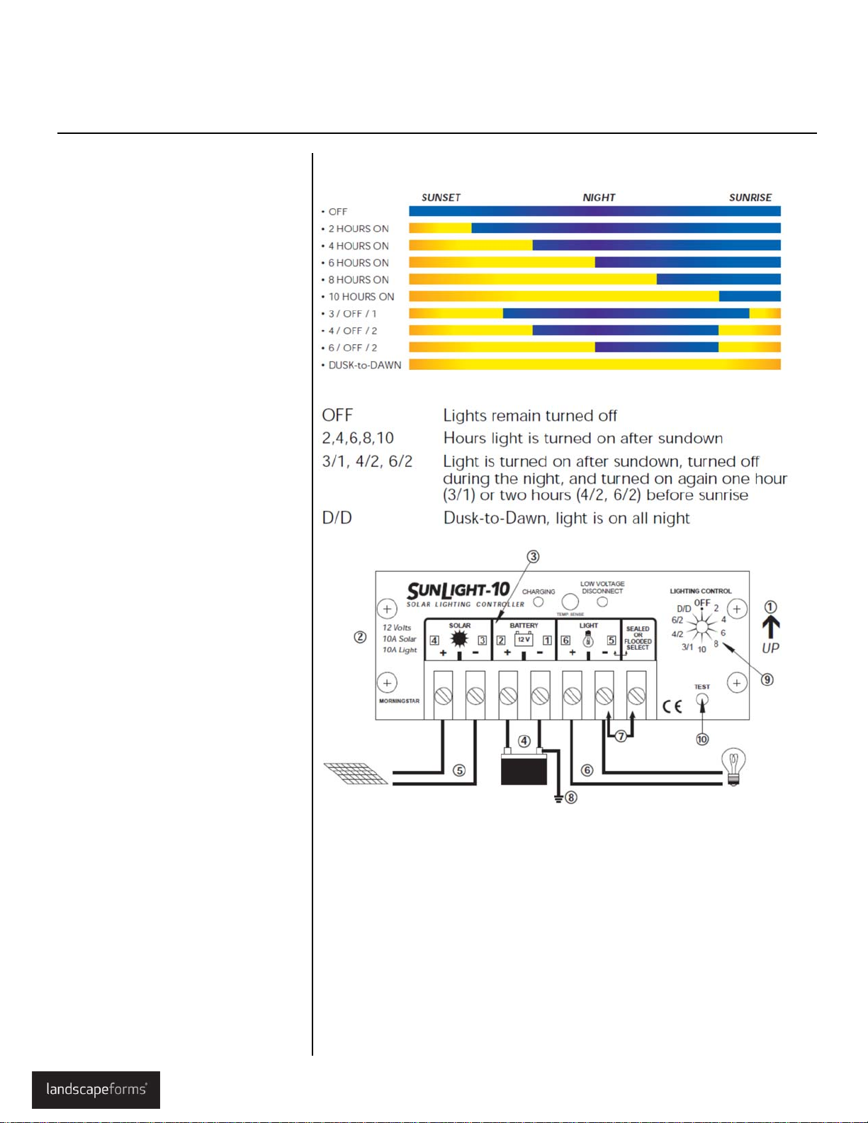
The unit is completely automatic, illuminating from dusk to dawn. Using the solar
panel mounted on the roof of the shelter tells the microcontroller if it’s daytime or
nighttime. Light is provided throughout the night without interruption, increasing
security and safety.
table of contents
Introduction 2
How It Works 2
Understanding Your Product 2
Installing the Smart Shelter 3
Maintenance/Product Care 5
Operation 6
Troubleshooting 7
Mechanical Installations Drawings 8

page 3 P 800.521.2546 F 269.381.3455 www.landscapeforms.com
1. Remove the lid to the Power Unit by
removing the 6 fasteners
2. Raise power unit to the roof and
space the power unit about 2-1/2”
back from the front edge of the
canopy panel. The wire slots in the
power unit should be toward the
back of the canopy.
3. Mark the location and drill and tap
(4) 5/16-18 holes to secure the
power module to the canopy.
4. Wipe down the roof panel and
make sure it is completely clean of
all dirt and debris. Remove the
adhesive backing from the solar
panel and stick it down about 3”
behind the power unit, centered
side to side on the roof panel. Be
careful not to wrinkle the panel or
trap air underneath it. This process
may be easier with two people.
Note: At this point, the solar panel
and the power unit should be
mounted to the shelter roof.
5. Mount Luminaire to interior of
shelter by centering on roof arc
(see installation positions - page
8). Drill and tap ¼-20 hole in shel-
ter using luminare base to locate
holes. Fix luminaires to shelter
using supplied ¼-20 screws.
Luminaires should be positioned to
direct light straight toward ground.
Pull wire harness from luminaire
module back to power module.
Route wire using interior cavity of
shelter roof arcs.
7. The wiring harnesses from the
luminaires will enter the power unit
through one of the wire slots.
System Components Overview:
Kaleidoscope® smart shelter installation and maintenance manual
Installation

page 4 P 800.521.2546 F 269.381.3455 www.landscapeforms.com
7. Connect the Weather Pak connectors
attached to the solar panel and the
power unit controller.
8. Plug the luminaire into the LED driv-
er. Match the gray to the red, and the
black to the black.
Note: On units with two luminaires the
wiring is as follows:
A. Connect the Gray wire from
luminaire 1 to the Red wire of the
LED driver
B. Connect the Gray wire from
luminaire 2 to the Black wire of
luminaire 1
C. Connect the Black wire from
luminaire 2 to the Black wire of
the LED driver.
All electrical connections are complete at
this point.
9. Switch the battery disconnect to the
On position.
10. Before re-installing power module lid
(removed in Step 1), complete system
test as follows:
Press the “test” button on the Morn-
ingStar control. At this point the lumi-
naire(s) should be lit.
11. After completion of test procedure,
secure power module lid using six
#10-32 fasteners.
The installation process is now complete.
USE EXTREME CAUTION WHEN INSTALLING
BATTERY HARNESS. ALWAYS WEAR INSULATING
GLOVES WHEN CONNECTING BATTERIES.
Kaleidoscope® smart shelter installation and maintenance manual
Installation

page 5 P 800.521.2546 F 269.381.3455 www.landscapeforms.com
Although the system is designed to be maintenance free, large performance gains
can be made with clean solar panels. Clean on an annual basis or as required. Use
water and a soft sponge or cloth for cleaning and a mild, non-abrasive cleaning agent
for more stubborn residue. Rinse well.
Clean solar panels more frequently during drier months, as they may become
soiled more quickly.
Note: During pressure washing, take care to avoid direct spray into drain holes on
power module lid.
• The main housing has several drain holes. Ensure that they are free of debris.
• Visual inspection – check over exterior assembly for cracks, missing or broken
hardware or other potential problems annually.
Batteries: Be cautious when handling the battery pack. It is capable of generating
hazardous short-circuit currents. Remove all jewelry (bracelets, metal-strap watches,
rings) before attempting to handle or disassemble the battery pack.
Consult your local municipal by-laws for information on recycling
the cells. DO NOT THROW THE CELLS IN THE GARBAGE!
Kaleidoscope® smart shelter installation and maintenance manual
maintenance / product care

page 6 P 800.521.2546 F 269.381.3455 www.landscapeforms.com
Turn the rotary LIGHTING CONTROL
switch to the lighting option desired.
Factory set for Dusk to Dawn operation.
Day-Night Transition
The SunLight uses the solar array to de-
tect day and night. The transition to night
requires a solar insolation level less than
2 percent. The transition back to day re-
quires a high solar array open-circuit volt-
age. Both state changes require 10
minutes of continuous transition values
before making the change. These con-
straints avoid false transitions due to
lightning or dark storm clouds.
Measure Night Length
The LIGHTING CONTROL options that turn
the lights on again before sunrise require
that the SunLight measure the length of
the night. Therefore, the controller cannot
turn the lights on before sunrise the first
night after installation (or after reconnect-
ing the battery). If the solar array is
disconnected during service, the control-
ler will then measure a faulty night length.
Either reset the controller by reconnecting
the battery, or this short “night” will be
automatically corrected by the controller
after 4 days of service.
Low Voltage Disconnect (LVD)
If the battery falls below 11.7 volts, the
load is disconnected from the battery to
protect against harmful deep discharges.
A one minute delay prevents load
disconnects from transients. The load is
automatically reconnected when the bat-
tery voltage recovers to 12.8 volts.
Lighting Control Options
Kaleidoscope® smart shelter installation and maintenance manual
operation

page 7 P 800.521.2546 F 269.381.3455 www.landscapeforms.com
Load not operating properly
1. Press the TEST button to turn the lights on. This will assist in troubleshooting
the problem.
2. Check that the load is turned on. Check that no system fuses are defective.
Check that no system circuit breakers are tripped. Remember that there are
no fuses or circuit breakers inside the SunLight.
3. Check connections to the load, and other controller and battery connections.
Make sure voltage drops in the system wires are not too high.
4. Check for proper LED indications on the SunLight. If the red LOAD DISCON-
NECT LED is on, the load has been disconnected due to low battery voltage.
This is generally a normal state when the load exceeds the PV array output
due to weather and other sunlight conditions.
5. Check the PV array voltage under direct sun, with the array leads disconnect-
ed. The voltage should be close to the expected open circuit voltage for the
panel type used.
6. Visually inspect the PV array and verify that the array is clear of debris (e.g.
leaves, snow, dirt) and that it is oriented correctly for the installation location.
7. Measure the voltage at the controller BATTERY terminals. If this voltage is
above the LVD, the load should have power. Press the test button and then
measure the voltage at the controller LOAD terminals, and if there is no volt-
age present, the controller may be defective.
Kaleidoscope® smart shelter installation and maintenance manual
troubleshooting

page 8 P 800.521.2546 F 269.381.3455 www.landscapeforms.com
Note: The 4-post unit uses one 2-post
system and one 3 -post system
Kaleidoscope® smart shelter installation and maintenance manual
mechanical installation locations

Kaleidoscope designed by Robert Chipman, ASLA;
Brian Kane, IDSA; and Arno Yurk, AIA, IDSA.
Kaleidoscope design is protected by Patent Nunbers: D432,665; D420,812;
D421,132; D429,000; D412,993; D413,314; D420,233; D420,812.
SpecificaƟons are subject to change without noƟce.
Kaleidoscope is manufactured in U.S.A.
©2014 Landscape Forms, Inc.
Printed in U.S.A.
OUR PURPOSE IS TO ENRICH OUTDOOR SPACES
We believe in the power of design and its ability to influence and elevate the
quality of public space. High quality products and outstanding customer
experience make us one of the world’s premier designers and manufacturers
of outdoor commercial furnishings.
Kaleidoscope® smart shelter installation and maintenance manual
P 800.521.2546 F 269.381.3455
7800 E. Michigan Avenue, Kalamazoo, MI 49048
Email: specify@landscapeforms.com
www.landscapeforms.com
Table of contents
Other Landscape Forms Shelter manuals
Popular Shelter manuals by other brands

ShelterLogic
ShelterLogic ShelterCoat 12'W x 8'H Peak manual

Storage Canopy
Storage Canopy C3340 Assembly manual

TMG
TMG PRO Series product manual

NBB
NBB SR8301-F Assembly instructions

Haws
Haws 9035 Installation, operation & maintenance instructions

Storage Canopy
Storage Canopy 26x40x10 Container Shelter Single truss Assembly manual