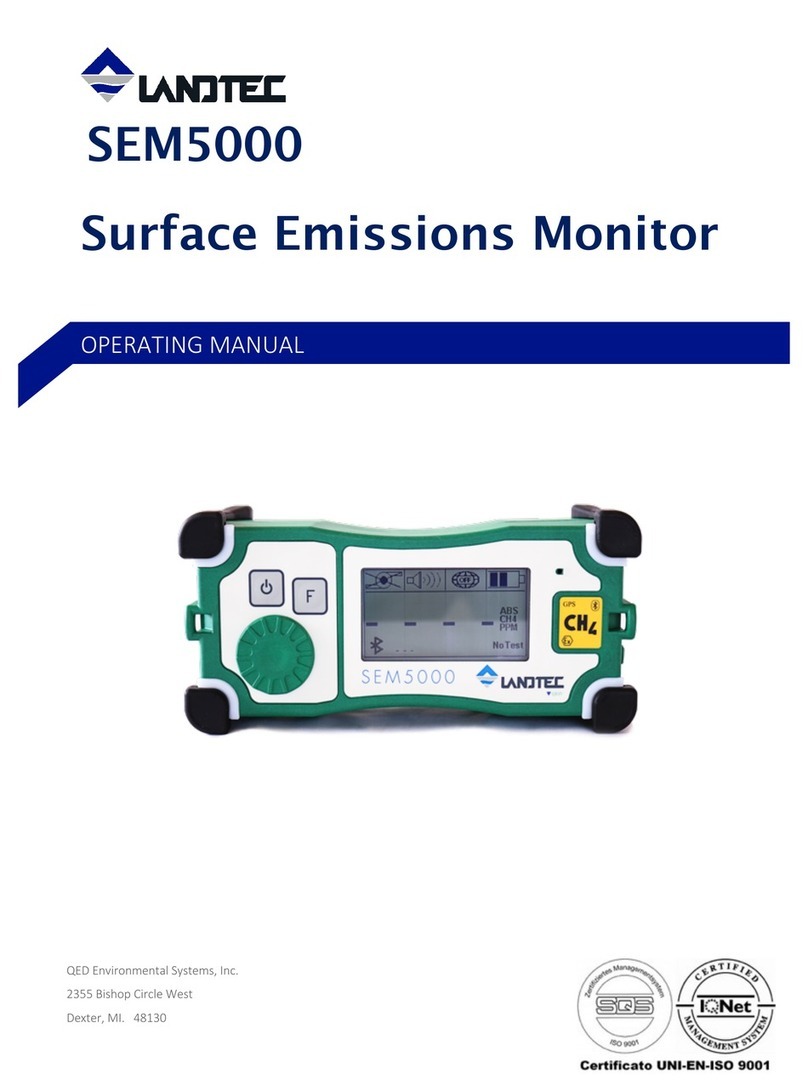
LANDTEC SEM5000 User manual

1
USER GUIDE
VERSION 3.0
SOFTWARE VERSION (707074) 40.07

2
INDEX
1 GENERAL DESCRIPTION.................................................................................................................................... 3
2 USER INTERFACE ................................................................................................................................................. 4
2.1 OVERVIEW........................................................................................................................................................... 4
2.2 CONNECTIONS ..................................................................................................................................................... 4
2.3 DISPLAY .............................................................................................................................................................. 5
2.4 NAVIGATION SYSTEM (MENU) ............................................................................................................................. 6
3 INSTRUMENT FUNCTION ................................................................................................................................... 7
3.1.1 Switch ON ................................................................................................................................................... 7
3.1.2 Switch OFF................................................................................................................................................. 7
4 START WORK......................................................................................................................................................... 8
4.1 USE OF GPS......................................................................................................................................................... 8
4.1.1 GPS Activation............................................................................................................................................ 8
4.2 TEST EXECUTION ................................................................................................................................................. 9
4.2.1 AIR test ....................................................................................................................................................... 9
4.2.2 GAS test .................................................................................................................................................... 10
4.2.3 UP WIND test ........................................................................................................................................... 11
4.2.4 DOWN WIND test..................................................................................................................................... 11
4.2.5 Result ........................................................................................................................................................ 11
4.2.6 Stop the test sequences.............................................................................................................................. 11
4.3 SAVING LOCATION............................................................................................................................................. 12
4.4 DELETE DATA .................................................................................................................................................... 12
4.5 DESCRIPTION OF THE PNEUMATIC CIRCUITS ...................................................................................................... 12
4.5.1 Malfunction of the pneumatic circuit / Pump OFF................................................................................... 12
4.5.2 Restarting the pump operation.................................................................................................................. 13
5 SETTING FUNCTION .......................................................................................................................................... 14
5.1 MEASUREMENT RANGE ..................................................................................................................................... 14
5.1.1 Methane measurement .............................................................................................................................. 14
5.1.2 Measure in absolute mode (ABS) and relative mode (REL) ..................................................................... 14
5.2 ACOUSTIC AND VISUAL ALARM ......................................................................................................................... 14
5.3 BACKLIGHT -DISPLAY ILLUMINATION .............................................................................................................. 15
5.4 LCD CONTRAST................................................................................................................................................. 15
5.5 BLUETOOTH ...................................................................................................................................................... 15
5.6 RECHARGING THE BATTERY PACK ..................................................................................................................... 15
6 MAINTENANCE.................................................................................................................................................... 16
6.1 REPLACING THE BATTERY PACK ........................................................................................................................ 16
6.2 REPLACING THE HYDROPHOBIC FILTER ............................................................................................................. 17
7 CALIBRATION...................................................................................................................................................... 17
7.1 ALARMS AND ERROR INFORMATION ................................................................................................................. 18
8 WARRANTY .......................................................................................................................................................... 19
9 APPENDIX A –SAFE USE OF THE INSTRUMENT ................................................................................... 20
9.1 LASER RADIATION ............................................................................................................................................. 20
9.2 OTHER PRECAUTIONS FOR THE USAGE ............................................................................................................... 20
9.3 TESTING AND MAINTENANCE............................................................................................................................. 20
9.4 REPAIR .............................................................................................................................................................. 20
10 APPENDIX B –TABLE OF CHARACTERISTICS ...................................................................................... 21

3
1GENERAL DESCRIPTION
The SEM5000 is a digital gas detection instrument from QED Environmental
Systems, Inc. The intended use of the SEM5000 is the measurement of low
concentrations of methane in the field (Landfill surface emissions monitoring,
leakage surveys of natural gas networks, control pinpointing outside buildings,
quantifying methane fluxes, and laboratory applications for gas analysis).
The instrument is selective exclusively to methane, thanks to the patented
Laser technology inside. The SEM5000 delivers reliable and accurate
measurement of methane concentrations, even if the sample contains other
gases or hydrocarbons. Due to its lightweight design and modest size, the
SEM5000 can be easily transported and is ideal for measuring methane
concentrations in the field, (landfills, site investigations or gas networks).
Thanks to its metrological sensitivity, accuracy, stability and response time,
the SEM5000 is the perfect instrument for the detection and quantification of
methane emissions.
The single-dial function selector makes the SEM5000 easy to use and the
large, back-lit LCD-display provides easy to read menus and results. The
SEM5000 has a measuring range covering 0 to 1,000,000 PPM (part per
million) or 100% methane concentration. The SEM5000 also offers a rapid
response time, improving the efficiency and saving time. The exceptional
reactivity of the SEM5000 laser technology provides excellent results during
field scans for fugitive traces of methane. The noteworthy combination of high
sensitivity and rapid response deliver outstanding measurement quality. The
SEM5000 is provided with integral GPS and Bluetooth, eliminating the need for
additional devices. The internal memory is capable of storing up to 480 hours
of scan data.
The SEM5000 is the perfect, easy-to-use instrument for accurately measuring
and recording methane concentrations during surface emissions monitoring.
CAUTION: DO NOT CHARGE THE BATTERY IN AREAS CLASSIFIED AS
HAZARDOUS.
ATTENTION: The photos shown in this user manual are indicative.

4
2USER INTERFACE
2.1 Overview
Description
[1]
ON/OFF button + Backlight
[2]
Function button
[3]
Buzzer
[4]
Selector Dial
[L]
LED Alarm Lights and Impact Bumpers
[S]
Strap Connectors
2.2 Connections
Description
[1]
Gas Sample Inlet
[2]
GPS Antenna Connector
[3]
Battery Charge Connector
[1]
[2]
[3]
[4]
[L]
[S]
[1]
[2]
[3]

5
2.3 Display
SECTOR
DESCRIPTION
[A]
Save Location
[A1]
Pump Status
[A2]
Tests Icons
[B]
Alarm Status
[C]
GPS Status
[D]
Battery Status
[E]
Measurement of Methane
[E1]
Type of view: ABS (absolute)
[E2]
Scale of Measurement: PPM (parts per million) – % VOL
(volume)
[F]
Bluetooth
[F1]
Bluetooth Connected with PC
Attention: this icon indicates that the instrument is
connected with the PC. Data will be saved in the PC and not the
device.
[G]
% of Memory Used
[H]
Gas Threshold
[I]
Information (data download, test results etc.)
[A]
[B]
[C]
[D]
[E]
[F]
[G]
[E1]
[E2]
[H]
[I]
[F1]
[A1]
[A2]

6
2.4 Navigation System (menu)
Push the green selector dial and the menu will
appear in the display window [E].
Use the selector dial to scroll through the
available menu options. Once you have identified
your desired option, push the selector dial to
confirm your selection.
While a menu is active, the value of the gas is
shown in the upper right corner of the display
[D]. The threshold value of the test is shown in
the lower right corner of the display [H].
(See Section 4.2 for additional information).
Select “ESC” to exit the Menu.
ON/OFF GPS
Start Test
ON/OFF Alarm
Concentration Threshold
_____ PPM
Reading Interval
Delete Memory
LCD Contrast
End test
Esc
[D]
[H]
[E]

7
3INSTRUMENT FUNCTION
3.1 Switch ON and Switch OFF
3.1.1 Switch ON
Press the ON/OFF button [1] for few seconds,
until the display is activated.
The start sequence includes several steps:
-Logo Landtec
-Information about the version of the
instrument firmware, serial number of
the instrument, next calibration date
NOTE - If there is existing data in the unit from
a previous scan, you will see the message
"DATA TO DOWNLOAD". In order to download
the data, you must use the SEMsoft software.
The instrument will warm up and calibrate
itself. The warm up lasts approximately 20
seconds. The instrument’s functions are not
available during the warm up period.
Once the warm up and calibration are
complete, the four LED lights will blink and the
alarm will sound.
The SEM5000 is now ready to operate.
3.1.2 Switch OFF
To switch off the instrument, press and hold
the ON/OFF button [1] for a few seconds. A
shut off message will appear on the display
and will count down to shut off.

8
4START WORK
4.1 Use of GPS
Upon start up, the GPS is not active. It must be activated prior to testing.
Note: Data is only acquired and saved when the GPS is active.
4.1.1 GPS Activation
Connect the external GPS antenna.
To activate the GPS, press the selector dial
and rotate the dial to scroll through the menu
options until “ON/OFF GPS” appears. Press the
selector dial to confirm the selection. The GPS
icon will change status from “Off” to “Active”.
The "Save Location" icon will appear in the
upper left-hand corner of the display.
The percentage of memory used will be
displayed in the bottom left-hand corner.
Initially, only the percent symbol, (%), will be
displayed. Once the GPS has stabilized and the
SEM5000 begins saving data, a number will
appear next to the percent symbol to indicate
what percentage of the memory has been
used.
Icon
Description
Icon
Description
GPS active but waiting for
signal
GPS off
GPS active
Save location
The GPS module is a high performance receiver with the ability to track up to
20 satellites. The antenna is a standard, high gain, vehicular type that provides
quality tracking performance.
Start-up time for the GPS module can vary according to the strength of the
actual signal received. The presence of high trees or buildings, aerial power
lines or other obstructions will affect the signal. Typically, in an open area, the
GPS will fix in less than a minute.
In the event of signal loss during the survey, the instrument will continue to
log gas values, and will associate the last saved tracked GPS position.

9
4.2 Test Execution
At any time of the work, you can perform the tests
of the instrument.
To start the test sequence, press the Selector Dial
and rotate it until “TEST” appears in the menu
screen.
Press the Selector Dial to activate the selection.
The test is composed of a sequence of 8 steps:
-AIR Test: Defines the average of the
bottom of the concentration threshold. This
test is repeated three times
-GAS Test: Defines the average of the top of
the concentration threshold. This test is
repeated three times
-UP WIND: Defines concentrations in
ambient air
-DOWN WIND: Defines concentrations in
ambient air
The sequence is:
1. AIR - 1
2. GAS 500 – 1
3. AIR – 2
4. GAS 500 – 2
5. AIR – 3
6. GAS 500 – 3
7. UP WIND
8. DOWN WIND
Attention: GPS must be active to perform the tests!
Attention: Do not switch OFF the SEM5000 during the tests!
4.2.1 AIR Test
After beginning the test sequence, the icons in the
upper left hand corner, [A] will change status. The
pump stops and test instructions will appear on the
display [I].

10
Connect the tube from the air cylinder to the
SEM5000 inlet, [1].
Press the “Function” button [2] to start the
test “AIR - 1”.
TEST STARTED will appear on the display and
the pump will start.
Press the “Function” button [2] to stop the test
after you have reached a stabilized reading.
Attention: The duration of this test is min 10 seconds / max 200
seconds.
4.2.2 GAS Test
When the AIR test is finished, the GAS test icon will
appear. The icon will appear as GAS500 or GAS250,
depending you max threshold.
Connect the tube of the gas cylinder to the
SEM5000 inlet, [1].
Press the “Function” button [2] to start the
test “GAS 500- 1”.
TEST STARTED will appear on the display and
the pump will start.
Press the “Function” button [2] to stop the test
after you have reached a stabilized reading.
Attention: The duration of this test is min 0
seconds / max 30 seconds.
Attention: If the test fails, you'll have to do it
again.
Repeat these steps for the remaining tests, (AIR – 2 / GAS 500 – 2 /
AIR – 3 / GAS 500 – 3).

11
4.2.3 UP WIND Test
When the last GAS test is finished, the icon for the UP WIND test will appear
and the pump will stop.
Note - You don’t require any gas/air cylinder for this test.
Move to your up wind position.
Press the “Function” button [2] to start the UP WIND test.
TEST STARTED will appear on the display and the pump will start.
Press the “Function” button [2] to stop the test after you have reached a
stabilized reading.
Attention: The duration of this test is min 10 seconds / max 300
seconds.
4.2.4 DOWN WIND Test
When the UP WIND test is finished, the icon for the DOWN WIND test will
appear and the pump will stop.
Move to your downwind position.
Press the “Function” button [2] to start the DOWN WIND test.
TEST STARTED will appear on the display and the pump will start.
Press the “Function” button [2] to stop the test after you have reached a
stabilized reading.
Attention: The duration of this test is min 10 seconds / max 300
seconds.
4.2.5 Result
At the end of the “DOWN WIND” test, the average of the three tests performed
will appear on the display in the lower right sector of the display [H].
This value will be the alarm threshold for the exceedance and will be stored in
the instrument for one day. The next day, you have to perform a new
sequence of test to have a value again.
You can see the value also in the menu “Threshold LAS”.
4.2.6 Stop the Test Sequence
There are two possibilities to stop the sequence of
tests:
-Wait until the “DOWN WIND” test is finished
-Press the Selector Dial and rotate it until the
menu displays “END TEST” and press the
Selector Dial again.

12
4.3 Saving Location
If the GPS is ON and the icon is displayed, push the Function button
[2], it will save the location.
A message will appear on the display in section [I].
4.4 Delete Data
To delete the data stored in the instrument, press
the Selector Dial and rotate it until the menu
displays DELETE MEMORY. Press the Selector Dial to
confirm the selection.
You have to confirm again if you want to delete the
data.
4.5 Description of the Pneumatic Circuits
The device operates in sampling mode thanks to a membrane pump. The
typical flow is 0.8 l/m. The minimum flow is 0.7 l/m. For this value or a lower
value, control that the pneumatic circuit is not altered. The maximum flow is 1
l/m.
The use of accessories, such as the probe, can slightly reduce this flow. It is
then advised to only use the parts and accessories supplied by QED.
The gas entrance connector has a size of D2 X D4 mm.
A hydrophobic internal filter protects the device against any entrance of dust
or water. It is strongly advised to use an external dust filter in order to avoid
the accumulation of dirt in the internal filter.
Attention: The filter is not made to protect against chemicals.
Attention: avoid aspiration of water or dirt into the instrument because this causes
failures and malfunction of the pneumatic circuit and can in can damage seriously the
sensors.
4.5.1 Malfunction of the Pneumatic Circuit / Pump OFF
The instrument detects when the pump flow is
compliant, otherwise the pump stops, the LEDs light up,
the icon of the pump shows a cross and you will see the
message "PUMP ERROR" is displayed.

13
If you want to turn the pump off manually, press the jog
dial and scroll to the menu option "ON / OFF Pump" and
press the dial again. Once pressed, the “Pump” icon will
be displayed with an “X”.
Attention: this menu is avaiable only when the GPS is
ON and the “Save location” icon is present on the
display.
When the pump is off, the display shows five horizontal
lines “ - - - - - “.
CAUTION: the aspiration of water or impurities may cause malfunction of the
pneumatic circuit and in some cases the damage of the sensors.
Attention: if there is the interruption / suspension of the operation of the
pump, the instrument will stop logging. Near the % of memory, horizontal
lines appear "- - - - -", the display shows "Suspension research" [I] and the
"Save location" icon is replaced by the “Pump” icon.
The pump icon appears in the following cases:
- Error / malfunction
- Manual Stop of the pump
- Turning off the GPS
4.5.2 Restarting the Pump Operation
To turn on the pump again, press the Function botton [2]; the “X” over the
pump icon will disappear and the pump will start again.
The field [A] on the display (Upper, left-hand corner) can display two different
icons:
-When the GPS is off, the “Pump” icon is displayed.
-When the GPS is on, the “Save Location” icon is displayed.

14
5SETTING FUNCTION
5.1 Measurement Range
5.1.1 Methane Measurement
The measurement results are shown on the display [E].
The SEM5000 is able to measure the methane selectively, eliminating potential
for cross-gas effects, in a range 0-100% VOL. In the range 0-1000 the scale
displayed is PPM [E2], more than 1% the displayed scale is %VOL.
5.1.2 Measure in Absolute Mode (ABS) and Relative Mode (REL)
The status of the measurement is indicated on the display [E]. The measure in
absolute (ABS [E1]), is the measurement of the ambient concentrations,
normally included between 1.0 and 3.0 PPM. Normal background level of CH4 in
atmosphere is approximately 2.0 PPM.
It can be advantageous or comfortable for the user, to follow during the
inspection using the relative measure of the concentration (REL [E1.1]),
because it displays minor changes in the environmental concentration.
It acts as a contrast between the ambient concentration and the transient leak
of gas.
In order to indicate important ambient concentrations of methane, the limit of
validity of the relative measurements of the concentration is 5.0 PPM. It means
that, when the measure reaches the value of 5.0 PPM, the device switches
automatically in the absolute mode of display. The relative mode is recovered
when the concentration returns to a lower value (< 5.0 PPM).
5.2 Acoustic and Visual Alarm
The acoustic alarm sounds and the LED flashes, when the
instrument is switched ON and when the measured gas
has exceeded the alarm threshold.
The acoustic alarm can be enabled or disabled by using
the Selector Dial.
When the alarm is turned off, the alarm icon appears
crossed on the display. When the measured gas
concentration exceeds the alarm threshold the LED
flashes, even when the acoustic alarm is disabled.
[E1]
[E1.1]

15
5.3 Backlight - Display Illumination
To change the display illumination, push the button [1] until you reach the
desired illumination. The display has 4 levels of illumination.
5.4 LCD Contrast
To set the contrast of the display, press the Selector Dial and rotate it until
the menu “LCD contrast” appears. Press the Selector Dial to confirm the selection.
Rotate the Selector Dial to increase or decrease the numbers (from 10%
to 100%).
5.5 Bluetooth
Bluetooth is always active and appears with an icon on the display.
5.6 Recharging the Battery Pack
The SEM5000 is supplied only with its specific rechargeable battery pack.
The typical autonomy of the device in operation is 10 hours at ambient
temperature and with the backlight ON. Many factors as ambient temperature,
activation of the backlight or the alarms can modify this duration. The
technology of the battery is Lithium ion. This battery pack is not restricted
according the European and international regulations of dangerous goods.
Thus, the device can be transported by plane following the requirements of the
labelling of the package. The level of the charge of the battery is indicated on
the display by its own icon. It exist three levels of charge. The last level
corresponds to the last 30 minutes of operation at 20°C. The duration of the
complete charge cycle is typically 8 hours. The red light that lights on the
charger is a sign that the instrument is charging. When the instrument finishes
the charging, the light will turn green. Do not charge the battery with a
temperature under zero degree.
Advises about the use of the lithium ion technology:
In order to optimize the use and the lifetime of your battery, please, follow the
following advises:
Charge the battery with a temperature between the range [+10°; +30°C]
Let the battery to reach a complete discharge as possible
Store in a dry place at a temperature preferably not exceeding 30°C
Warning:
Do not Charge the battery pack in areas classified as “Hazardous”.
Do Not Charge battery when connected to the SEM5000

16
6MAINTENANCE
6.1 Replacing the Battery Pack
Warning: Replace the battery pack only in a safe place.
Allen Key 3mm
Battery pack
Unscrew the four
screws
The picture shows the
battery pack outside from its
compartment.
1
2
3
4

17
6.2 Replacing the Hydrophobic Filter
7CALIBRATION
Except a situation of damage or default, it is recommended that your unit ben
sent to QED annually for inspection and calibration.
The hydrophobic internal filter should be checked periodically, (recommended
weekly during periods of heavy use). It is recommended that the filer be
replaced quarterly.
Unlock the filter counterclockwise
and remove it.
Change the filter and reassemble clockwise

18
7.1 Alarms and Error Information
Visual Indication
Error Explanation
Recommendation
Acoustic alarm and flashing of
the LED lights
GAS alarm
Concentration measured above the alarm
threshold.
The display shows the message
ERROR PUMP, LED flashing and
the icon is crossed
Pump stopped
The pump has stopped due to ingress of water or a
high quantity of dust. Check/change water and dust
filters.
Flashing of the Battery icon
Low Battery
Battery charge is low. When icon flashes, the
battery will still provide about 30 minutes of use (at
+20°C).
Swap battery with fully charged spare and continue
with your scan.
Display shows: LOW BATTERY
Dead Battery
The battery charge has been fully depleted. The
SEM5000 will shut itself down.
Swap battery with fully charged spare and continue with
your scan.
Display shows: NO COMM
FROM LASER
Communication has
failed
Turn off and restart SEM5000. If the error persists,
contact the service.
Display shows: LASER SENSOR
ERROR 130
Communication has
failed
Turn off and restart SEM5000. If the error persists,
contact the service.
Display shows: LASER SENSOR
ERROR 135
Communication has
failed
Turn off and restart SEM5000. If the error persists,
contact the service.
Display shows: LASER SENSOR
ERROR 142
Communication has
failed
Turn off and restart SEM5000. If the error persists,
contact the service.
Display shows: LASER SENSOR
ERROR 144
Communication has
failed
Turn off and restart SEM5000. If the error persists,
contact the service.
Display shows: LASER SENSOR
ERROR 150
Communication has
failed
Turn off and restart SEM5000. If the error persists,
contact the service.
Resetting the alarms:
The table below indicates if it is possible or not to extinguish the alarm or
information of default when the device is in operation.
Alarm and information of default
Possibility and conditions of Reset
Threshold of concentration
Sound alarm: YES
Flashing of the red Led: NO
Pump stopped
Display indicator: NO
Battery level low
Display indicator: NO

19
8WARRANTY
This instrument is guaranteed, to the original end user purchaser, against
defect in materials and workmanship for a period of 3 years from the date of
the shipment to the user.
During this period QED will repair or replace defective parts on an exchange
basis.
The decision to repair or replace will be determined by QED.
To maintain this warranty, the purchaser must perform maintenance and
calibration as prescribed in the operating manual.
Normal wear and tear, and parts damaged by abuse, misuse, negligence or
accidents are specifically excluded from the warranty.
Note: Please contact Technical Support at (800) 968-2026 or email
[email protected] for further information.

20
9APPENDIX A – SAFE USE OF THE INSTRUMENT
The information contained in these safety instructions must be followed in
addition to the warnings in the user manual supplied to the customer.
DO not use the instrument SEM5000 in a classified area.
9.1 Laser Radiation
The instrument SEM5000 contains an invisible laser source. The instrument is
classified Class 3 according European standards.
Do not open the device
9.2 Other Precautions for Usage
The charging of the batteries must be performed in a safe place with the
appropriate external adapter.
The instrument is dedicated to measurements in ambient air or can
accept gas mixture containing non corrosive chemical products. In case of
the presence of gas mixture except that hydrocarbon and neutral gases,
contact QED to verify the compatibility with the device.
9.3 Testing and Maintenance
The checks and maintenance of certified equipment should be performed
according to the criteria of the standard EN60079-17.
9.4 Repair
In the event of malfunction or damage is recommended to send the equipment
to QED for repair.
Other manuals for SEM5000
1
Table of contents
Other LANDTEC Gas Detector manuals
Popular Gas Detector manuals by other brands

GMI
GMI Gasurveyor 11-500 User handbook

Ludlum Measurements
Ludlum Measurements 43-68 manual

EsiWelma
EsiWelma Sensigas URD20SS quick start guide

Helios
Helios KWL-VOC eC Installation and operating instructions

AGS
AGS Merlin 1000S+ Installation operation & maintenance

Evikon
Evikon PluraSens E2638 Series user manual