Lantronix XPort AR Quick setup guide
Other Lantronix Network Hardware manuals
Lantronix
Lantronix EDS8PR User manual

Lantronix
Lantronix XPress DR User manual

Lantronix
Lantronix Spider User manual

Lantronix
Lantronix WIBOX 2100 User manual
Lantronix
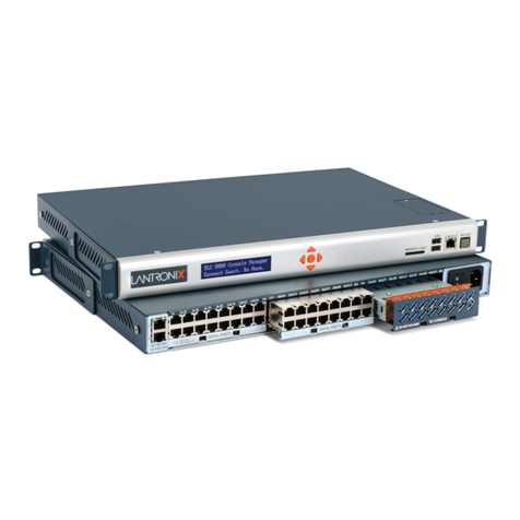
Lantronix SLC 8000 Series User manual
Lantronix
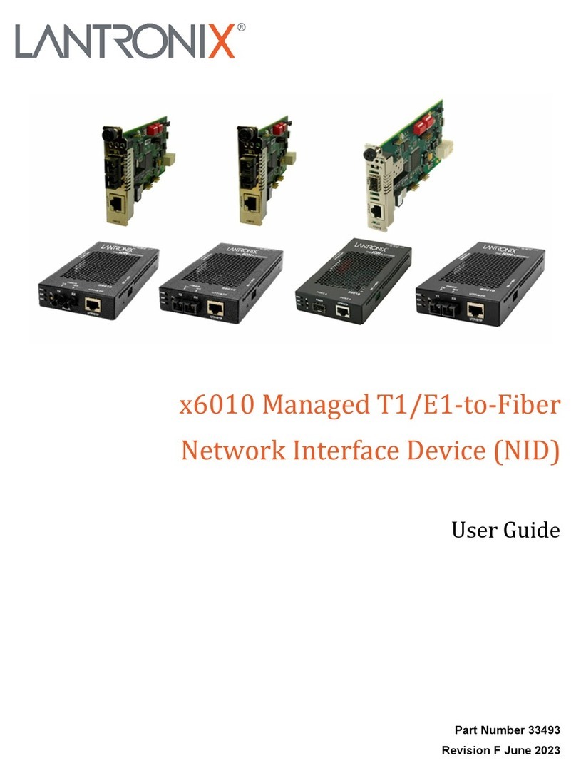
Lantronix x6010 User manual
Lantronix
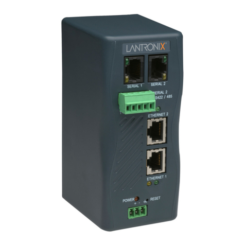
Lantronix XPress DR+ User manual
Lantronix
Lantronix SecureLinx User manual
Lantronix
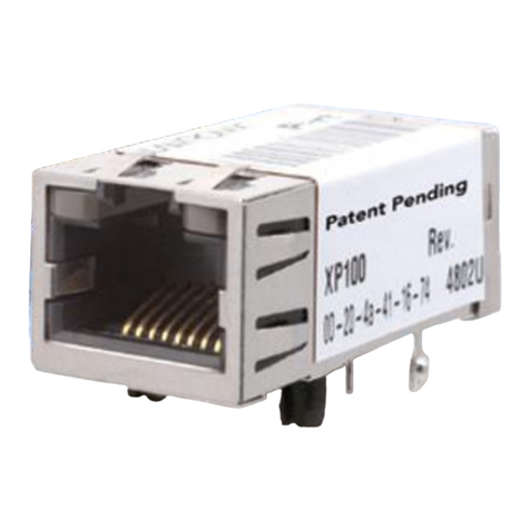
Lantronix XPort User manual
Lantronix
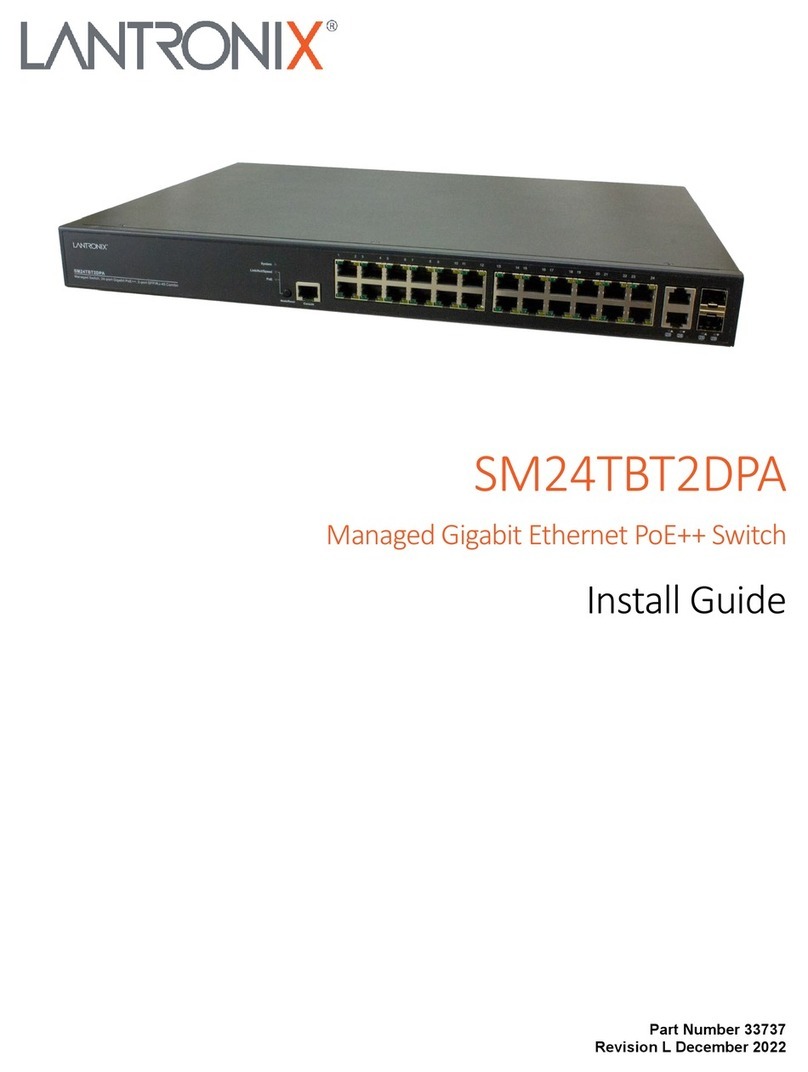
Lantronix SM24TBT2DPA User manual

Lantronix
Lantronix XPort AR User manual

Lantronix
Lantronix XPORT PROTM 900-560 User manual
Lantronix
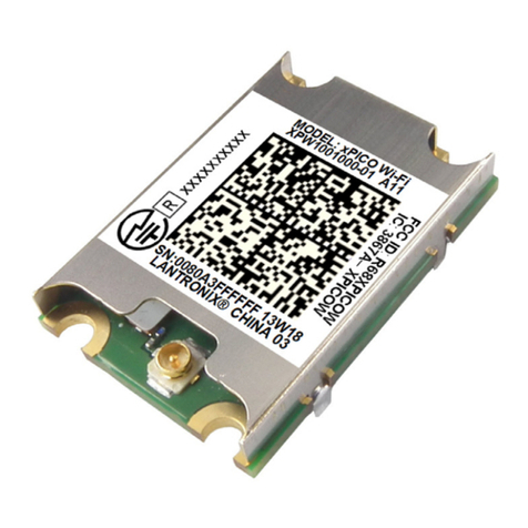
Lantronix xPico WiFi User manual

Lantronix
Lantronix ManageLinx User manual

Lantronix
Lantronix XPress DR+ User manual
Lantronix
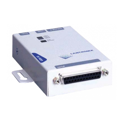
Lantronix Device Server UDS 10 Installation instructions
Lantronix
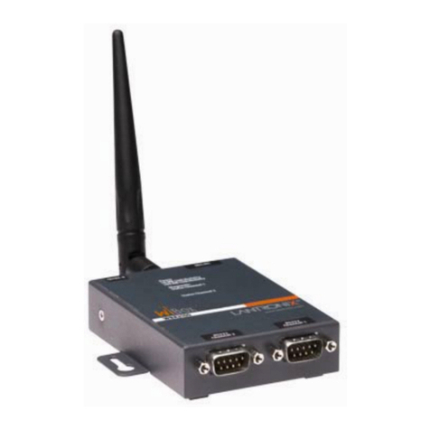
Lantronix WiBox 2100E User manual

Lantronix
Lantronix SLC 8000 User manual
Lantronix
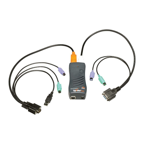
Lantronix Spider User manual

Lantronix
Lantronix SecureLinx User manual
Popular Network Hardware manuals by other brands

Matrix Switch Corporation
Matrix Switch Corporation MSC-HD161DEL product manual

B&B Electronics
B&B Electronics ZXT9-IO-222R2 product manual

Yudor
Yudor YDS-16 user manual

D-Link
D-Link ShareCenter DNS-320L datasheet

Samsung
Samsung ES1642dc Hardware user manual

Honeywell Home
Honeywell Home LTEM-PV Installation and setup guide
