manuals.online logo
Brands
  1. Home
  2. •
  3. Brands
  4. •
  5. LANZINI
  6. •
  7. Lighting Equipment
  8. •
  9. LANZINI TORRE FARO R2 DOUBLE User manual

LANZINI TORRE FARO R2 DOUBLE User manual

P06131010 www.lanzini.it
EN
INSTRUCTIONS
1 m
INSTALLATION, USE AND MAINTENANCE
- Warning! Security of the fitting is guaranteed only with the appropriate use of the
following instructions: therefore it is necessary to preserve them.
- Warning! Before connecting to the main network, during assembly or
replacement of the product, make sure to disconnect the tension.
- Warning! The product has to be repaired only by professional technicians or by the
manufacturer.
- During product installation respect carefully the plant rules.
- The fitting should be used only if complete with its protection screen; This is a 5 mm
thick tempered glass.
- For any replacement contact the manufacturing company.
- The fitting must be installed by a professional electrician.
- The fitting cannot be modified or tampered with in any way, any modification may
compromise security by making it dangerous. The manufacturer declines any
responsibility for the modified products.
- Class I fitting must be connected to the ground circuit of the electrical plant.
- Keep at least 1 m between the fitting and the illuminated surface.
- Fitting suitable for outdoor applications. Protection degree IP66.
- Fitting suitable for direct mounting on normally inflammable surfaces.
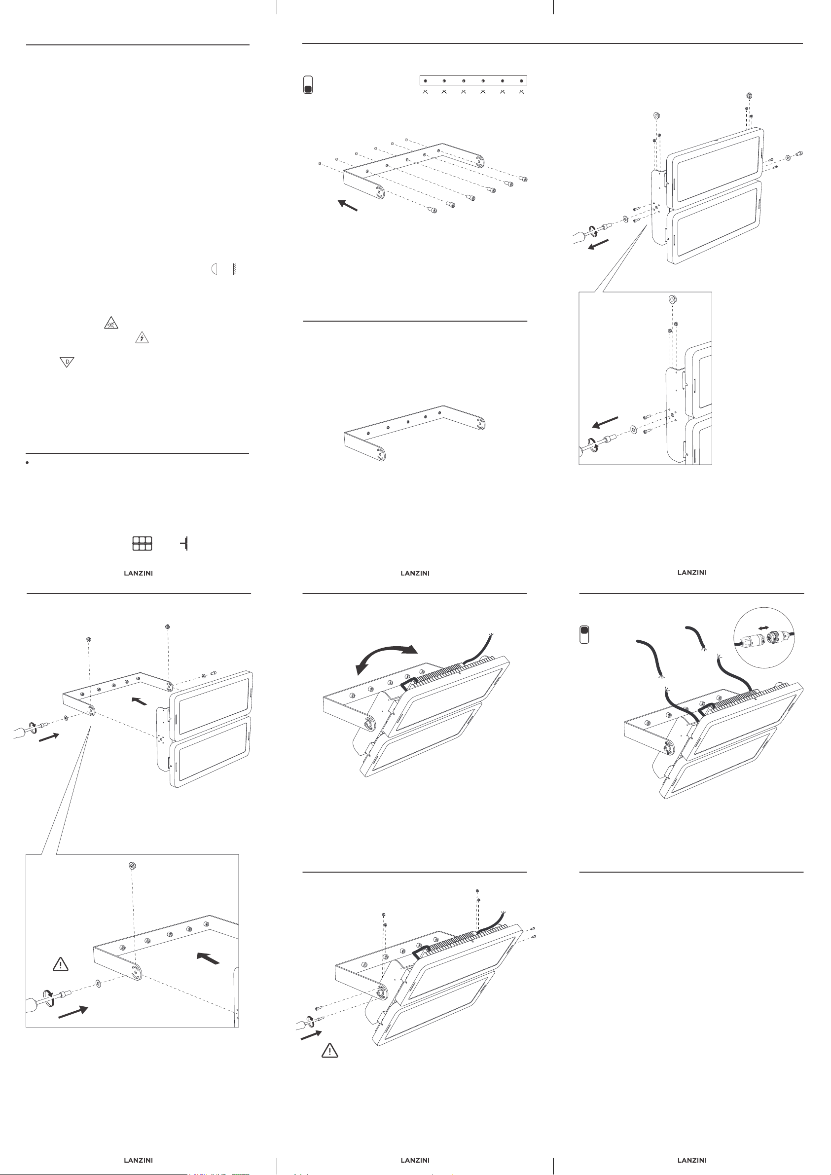
- Follow the illustrated procedure for a correct installation.
- Do not stare at light source.
- Warning! Risk of electric shock
- For use in environments where an accumulation of non-conductive dust on the
luminaire
- Power cable dimensions: from Ø 5 to Ø 10 mm
Recommended cables: H07RN-F 3G 1,5 (10 mm)
H05RN-F 3G 1,0 (8,1 mm)
FTG10OHM1 3G 1,0 (9,4 mm)
Operating temperature: -40° +45°C Insulation class: I
EP s.p.a. Via del Commercio 1 - 25039 - Travagliato (BS) - ITALY
FR
INSTRUCTIONS
INSTALLATION, USE AND MAINTENANCE
- Attention! La sécurité du projecteur est garantie uniquement avec l'utilisation
appropriée des instructions suivantes: vous devez donc les conserver.
-Attention! Avant de faire des connexions réseau, pendant l'assemblage ou le
remplacement du produit, assurez-vous que la tension a été supprimée.
- Attention! L'appareil ne peut être réparé que par du personnel spécialisé ou par le
fabricant.
- Pendant l'installation du système, respecter scrupuleusement la réglementation
actuelle de l'usine.
- L'appareil doit être utilisé uniquement s'il est complet avec son écran de
protection; ce sont des verres trempés de 5 mm d'épaisseur.
- Pour tout remplacement, contactez le fabricant.
- L'appareil doit être installé par un électricien professionnel.
- L'appareil ne peut être modifié ou altéré de quelque manière que ce soit une
modification peut compromettre la sécurité en le rendant dangereux.
- Class I fitting must be connected to the ground circuit of the electrical plant.
- Maintenez au moins 1 m entre l'appareil et la surface éclairée.
- Appareil adapte pour une utilisation en extérieur. Degré de protection IP66.
- Appareil adapte au montage direct sur des surfaces normalement inflammables.
- Ne regarde pas la source de lumière.
- Attention!Risque de chol électrique
- Pour une utilisation dans des environnements où une accumulation de poussière
non conductrice peut être attendue
- Taille du câble d'alimentation: deØ 5 à Ø 10 mm
Câbles recommandés: H07RN-F 3G 1,5 (10 mm)
H05RN-F 3G 1,0 (8,1 mm)
FTG10OHM1 3G 1,0 (9,4 mm)
Température de functionnement: -40° +45°C Classe de protection: I
R2 DOUBLE
TORRE FARO
MODEL
Power supply: 220-240 V 
Power Weight Surface exposed to the wind
Dimensions: 548×470×355 mm
200 W x 2 23 Kg 0,26 m² 0,06 m²
230 W x 2 23 Kg 0,26 m² 0,06 m²
250 W x 2 23 Kg 0,26 m² 0,06 m²
300 W x 2 23 Kg 0,26 m² 0,06 m²
200 W x 2 23 Kg 0,26 m² 0,06 m²
230 W x 2 23 Kg 0,26 m² 0,06 m²
250 W x 2 23 Kg 0,26 m² 0,06 m²
300 W x 2 23 Kg 0,26 m² 0,06 m²
EXTERNAL DRIVE
Voltage: 220-240 V 
Puissance Poids Surface exposée au vent
Dimensions: 548×470×355 mm
DRIVER EXTÉRIEUR
IP66 OUTDOOR
IT-Questo prodotto contiene una sorgente luminosa di efficienza energetica classe
EN-This product contains a light source of energy efficiency class
FR-Ce produit contient une source lumineuse de classe d'efficacité énergétiques
1 m
D

fig. B
fig. E
fig. F
fig. D
fig. C
fig. G
IT
1 m
ISTRUZIONI
DI INSTALLAZIONE, USO E MANUTENZIONE
- Attenzione! La sicurezza del proiettore è garantita solo con l’uso appropriato delle
seguenti istruzioni: pertanto è necessario conservarle.
- Attenzione! Prima di eseguire le connessioni di rete, durante il montaggio o
sostituzione del prodotto, assicurarsi di aver tolto la tensione.
- Attenzione! L’apparecchio è riparabile solo da personale esperto o dall’azienda
produttrice.
- Durante l’installazione del sistema rispettare scrupolosamente le norme
impiantistiche vigenti.
- L’apparecchio deve essere utilizzato solo se completo del suo schermo di
protezione; trattasi di vetro temprato spessore 5 mm)
- Per qualsiasi sostituzione contattare l’azienda produttrice.
- L’apparecchio deve essere installato da un elettricista professionista.
- L’apparecchio non può essere in alcun modo modificato o manomesso, ogni
modifica ne può compromettere la sicurezza rendendo lo stesso pericoloso.
L’azienda produttrice declina ogni responsabilità per i prodotti modificati.
- Gli apparecchi in classe I devono essere collegati al circuito di terra dell’impianto
elettrico.
- Mantenere almeno 1 m tra l’apparecchio e la superficie illuminata.
- Apparecchio idoneo al funzionamento in esterni. Grado di protezione IP66.
- Apparecchio idoneo al montaggio diretto su superfici normalmente infiammabili.
- Seguire la procedura illustrata per una corretta installazione.
- Non fissare la fonte di luce.
- Attenzione! Rischio di scossa elettrica
- Per l’uso in ambienti in cui può essere previsto un accumulo di polvere non
conduttrice
- Dimensioni cavo d’alimentazione: da Ø 5 a Ø 10 mm
Cavi consigliati: H07RN-F 3G 1,5 (10 mm)
H05RN-F 3G 1,0 (8,1 mm)
FTG10OHM1 3G 1,0 (9,4 mm)
fig. A
OFF
Installare la flangia di fissaggio a parete mediante le n° 6 viti.
Install the wall mounting flange using the 6 screws.
Installez la bride de montage mural à l'aide des 6 vis.
Controllare se la staffa è stata installata nel modo corretto.
Install the wall mounting flange using the 6 screws.
Vérifiez si le support a été installé correctement.
Svitare le n° 2 viti centrali dal prodotto e le viti di bloccaggio facendo attenzione al
posizionamento delle rondelle e dei dadi che saranno da riposizionare nello stesso
ordine nella fase di montaggio.
Unscrew the 2 central screws and the locking screws from the product paying
attention to the positioning of the washers and nuts that must be repositioned in the
same order during the assembly phase.
Dévisser les 2 vis centrales du produit et les vis de verrouillage en faisant attention
au positionnement des rondelles et écrous qui seront repositionnés dans le même
ordre lors de la phase d'assemblage.
6 Nm
Posizionare il faro all’interno della flangia, mantenendo entrambe le rondelle esterne
rispetto alla flangia nell’ordine: vite, rondella piana, rondella filettata, flangia e dado
interno.
Position the floodlight inside the flange, keeping both the washers external in respect to the
flange in the following order: screw, flat washer, threaded washer, flange and inner nut.
Positionnez le projecteur à l'intérieur de la bride, en gardant les deux rondelles extérieures
par rapport à la bride dans l'ordre: vis, rondelle plate, rondelle filetée, bride et écrou
intérieur.
Regolare l’inclinazione del faro come desiderato.
Adjust the inclination of the floodlight as desired.
Réglez l'inclinaison du projecteur comme désiré.
Serrare le n° 4 viti con i relativi dadi per bloccare e assicurare il faro in posizione.
Tighten the 4 screws with the corresponding nuts to lock and secure the floodlight in
place.
Serrez les 4 vis avec les écrous correspondants pour verrouiller et fixer le projecteur en
place.
3 Nm
ON
Collegare i 2 cavi di alimentazione utilizzando 2 connettori IP 3 poli (optional
LKITA00000000003) e riallacciare la tensione di alimentazione.
Connect the 2 power supply cables using 2 IP connectors 3 poles (optional
LKITA00000000003) and reconnect the supply voltage.
Connectez les 2 câbles d'alimentation à l'aide de 2 connecteurs IP 3 pôles
(LKITA00000000003 en option) et reconnectez la tension d'alimentation.
Tensione di alimentazione: 220-240 V 
Potenza Peso Superfice esposta al vento
Dimensioni: 548×470×355 mm
DRIVER ESTERNO
Temperatura di funzionamento: -40° +45°C Classe di isolamento: I
200 W x 2 23 Kg 0,26 m² 0,06 m²
230 W x 2 23 Kg 0,26 m² 0,06 m²
250 W x 2 23 Kg 0,26 m² 0,06 m²
300 W x 2 23 Kg 0,26 m² 0,06 m²

Other LANZINI Lighting Equipment manuals

LANZINI Gm User manual

LANZINI

LANZINI Gm User manual

LANZINI Evo M User manual

LANZINI

LANZINI Evo M User manual

LANZINI Pitagora User manual

LANZINI

LANZINI Pitagora User manual

LANZINI R2 DOUBLE TORRE FARO EXTRA User manual

LANZINI

LANZINI R2 DOUBLE TORRE FARO EXTRA User manual

LANZINI Gm User manual

LANZINI

LANZINI Gm User manual

LANZINI EVO XL TORREFARO User manual

LANZINI

LANZINI EVO XL TORREFARO User manual

Popular Lighting Equipment manuals by other brands

EuroLite LED KLS-200 user manual

EuroLite

EuroLite LED KLS-200 user manual

NANOLUX CMH-315NC operating manual

NANOLUX

NANOLUX CMH-315NC operating manual

Ironman4x4 ILANTERN004 owner's guide

Ironman4x4

Ironman4x4 ILANTERN004 owner's guide

Ignition Gawan 200 user manual

Ignition

Ignition Gawan 200 user manual

mbj SRL-12 operating manual

mbj

mbj SRL-12 operating manual

Zodiac CYCLONIC Series manual

Zodiac

Zodiac CYCLONIC Series manual

E2S D2xB1XH1 instruction manual

E2S

E2S D2xB1XH1 instruction manual

Endless Pools FastLane Planning guide

Endless Pools

Endless Pools FastLane Planning guide

Lumio INNOVAPLAS AQUARIUS DECK 5000 manual

Lumio

Lumio INNOVAPLAS AQUARIUS DECK 5000 manual

VIO HALCYON STRIP INSTALLATION MANUALS AND SAFETY INFORMATION

VIO

VIO HALCYON STRIP INSTALLATION MANUALS AND SAFETY INFORMATION

Trilux 7131 Series Disassembly instructions

Trilux

Trilux 7131 Series Disassembly instructions

JB Systems Smooth Scan-3 MK2 Laser Operation manual

JB Systems

JB Systems Smooth Scan-3 MK2 Laser Operation manual

ETC Aero Wave Station installation guide

ETC

ETC Aero Wave Station installation guide

iGuzzini PALCO IN-OUT EH87 instruction sheet

iGuzzini

iGuzzini PALCO IN-OUT EH87 instruction sheet

Lencarta UltraPro 300 instructions

Lencarta

Lencarta UltraPro 300 instructions

Pixapro EzyLite Softbox 850W Manual instruction

Pixapro

Pixapro EzyLite Softbox 850W Manual instruction

Castaldi Lighting D22 Installation and maintenance sheet

Castaldi Lighting

Castaldi Lighting D22 Installation and maintenance sheet

ML Accessories T8LED Series Installation & maintenance manual

ML Accessories

ML Accessories T8LED Series Installation & maintenance manual

manuals.online logo
manuals.online logoBrands
  • About & Mission
  • Contact us
  • Privacy Policy
  • Terms and Conditions

Copyright 2025 Manuals.Online. All Rights Reserved.