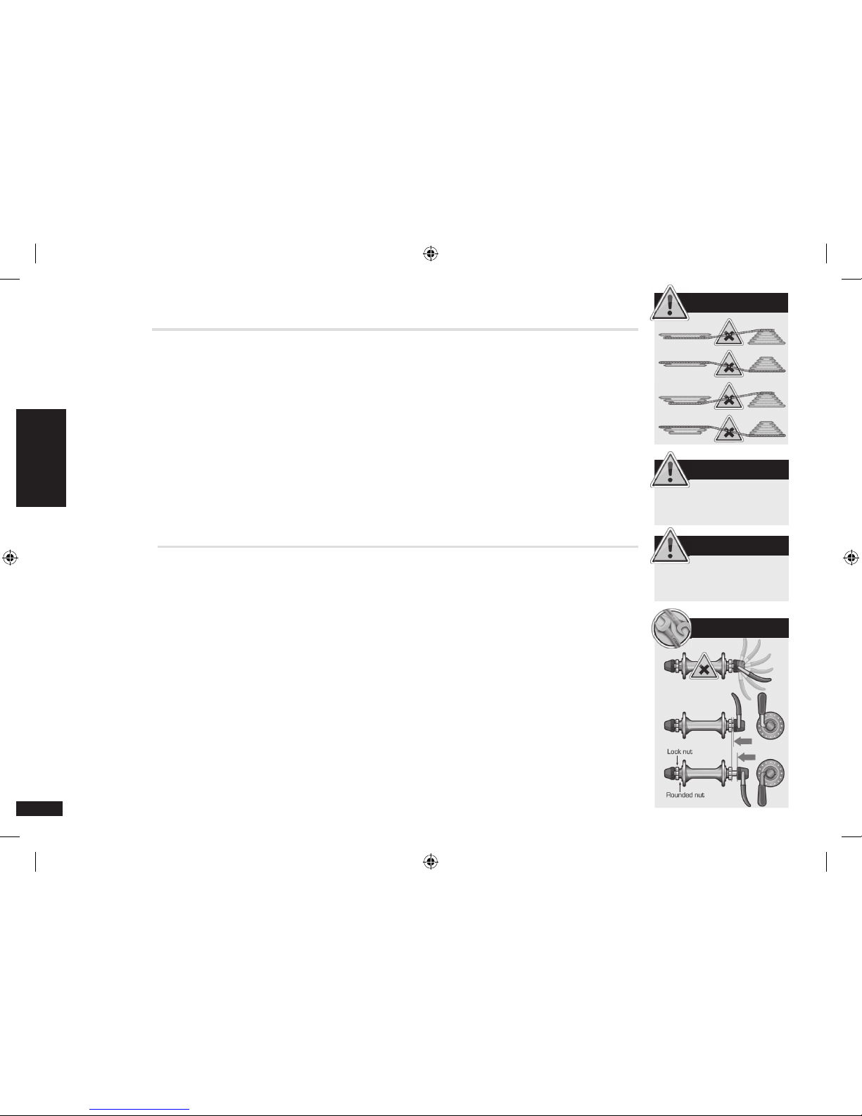
Lapierre EN14764 User manual

CONTENTS - 1
You have just acquired a Lapierre bike and we
would like to take this opportunity to thank
you for your purchase. Lapierre, based in Dijon,
France, since 1946, is pleased to provide you
with innovative solutions for enjoyable riding.
This manual is designed to help you fully
understand your Lapierre bike for an optimal
performance.
I - WELCOME
1 - ABOUT OUR BIKES
2 - DEFINITIONS AND RESTRICTIONS
3 - SAFETY AND USAGE
II - SETTING
1 - RIDING
1.1 SADDLE HEIGHT
1.2 SADDLE POSITION
1.3 STEM AND HANDLEBARS
1.4 HEADSET
2 - DRIVETRAIN
2.1 REAR DERAILLEUR
2.2 FRONT DERAILLEUR
2.3 BRAKES
2.4 WHEELS
3 - RECOMMENDATIONS
3.1 TORQUES SPECIFICATIONS
3.2 SUSPENSION FORKS
III - SPECIFIC MODELS
1 - CARBON MODELS
2 - RAID FX
3 - X-CONTROL (FPS2)
4 - X-FLOW ( PENDBOX)
5 - XR
6 - ZESTY/SPICY/FROGGY (OST/OST+)
7 - THRU AXLE ADJUSTMENT
8 - DH (PENDBOX)
9 - INTEGRATED SEATPOST TIGHTENING SYSTEM RAPT 2.1•2.2•DH
10 - ADS (ADJUSTABLE DROPOUT SYSTEM) RAPT 2.1 • 2.2
IV - MAINTENANCE
1 - MAINTENANCE SCHEDULE
2 - CLEANING YOUR BIKE
3 - WORN PARTS
V- GENERAL WARRANTY CONDITIONS
2
3
5
6
6
6
7
8
9
9
9
10
10
11
11
11
12
12
13
14
15
16
17
18
19
19
20
21
21
22
CONTENTS
ENGLISH
PAGES_INTER2013.indd 1 23/11/2012 08:25:09

2 - WELCOME
WARNING
FOR YOUR SAFETY, ALWAYS
WEAR THE NECESSARY
PROTECTIVE GEAR.
MAKE SURE YOU HAVE ON
APPROPRIATE CLOTHING AND
THAT YOU ARE VISIBLE TO
AUTOMOBILES.
WEARING A HELMET IS
STRONGLY RECOMMENDED.
IF YOU FALL, MAKE SURE YOU
CAREFULLY INSPECT YOUR
BIKE BEFORE RIDING AGAIN.
IF YOU DETECT A PROBLEM,
DO NOT USE YOUR BIKE UNTIL
IT HAS BEEN FIXED.
CHECK YOUR BIKE BEFORE
EVERY RIDE.
WARNING
PLEASE READ THIS MANUAL
CAREFULLY BEFORE USING
YOUR BIKE. FOR MAINTENANCE
AND SETTINGS FOR
COMPONENT PARTS, PLEASE
REFER TO THE SUPPLIERS’
MANUALS DELIVERED WITH
YOUR BIKE.
1 - ABOUT OUR BIKES
Lapierre’s R&D headquarters are also located in Dijon, at the main production site. Our engineers are
on hand to take your needs as a cyclist into consideration when developing new concepts and ideas.
All of the different aspects, from geometries and technologies to materials and components, are
closely studied to offer you unparalleled comfort and performance.
The members of the R&D department also work closely with the riders from Team Lapierre
International (MTB) and the FDJ BIGMAT (professional road team) in order to benefit from their
experiences at the highest levels of competition.
Each one of our models is developed with a particular style of riding in mind, and we pay close
attention to even the tiniest detail to offer you a top quality product. All of our bikes are individually
assembled by a Lapierre specialist, whose signature you’ll find on the Quality Check accompanying
your purchase.
Lapierre bikes conform to the security standards listed below, as described in the new European
norms:
- EN14764: “Bicycles used on public highway”
- EN14765: “Bicycles for young children”
- EN14766: “Mountain bicycles”
- EN14781: “Road bicycles”
Lapierre bikes are developed for top performance in specific riding conditions, and they can be
divided into different categories according to the terrain for which they were created.
Not respecting the intended use of the bike can pose potential risks to the rider.
When you purchase a Lapierre bike, you are buying the highest quality product that we can offer you.
Thank you for your trust, and we look forward to accompanying you on many rides.
I - WELCOME
ENGLISH
PAGES_INTER2013.indd 2 23/11/2012 08:25:09

WELCOME - 3
I - WELCOME
2 - DEFINITIONS
FRAME
1- Top tube
2- Down tube
3- Seat tube
4- Head tube
5- Chain stays
6- Seat stays
7- Bottom bracket
8- Fork
9- Rear shock absorber (Only on full-suspension MTB)
DRIVETRAIN
10- Front / Rear derailleur
11- Cranks
12- Chainrings
13- Chain
14- Sprocket (individual cogs)
15- Pedals (depending on the type of bike)
16- Derailleur hanger
WHEELS
17- Front / Rear hub
18- Spokes
19- Front / Rear rim
20- Tires
21- Valve
22- Quick release
23- Front / Rear brakes (V-Brake or disc brake
depending on the type of bike)
COMPONENT PARTS
24- Handlebar
25- Stem
26- Brake levers
27- Shifters
28- Grips
29- Cables
30- Outer cable
31- Saddle
32- Saddle clamp
33- Seat Post
34- Seat Post Clamp
35- Headset
36- Linkage
ENGLISH
16
14
21
17
18
23
10
6
19
20
10
29
13
15
5
12
7
24
25
26
28
27
4
35
11
33
3
2
36
1
32
31
28
34
21
17
18
22
8
23
9
30
19
20
PAGES_INTER2013.indd 3 23/11/2012 08:25:09

4 - WELCOME
CONDITION 4
ALL TYPES OF RIDING.
CONDITION 4
CONDITION 3
INCLUDES RIDING
CONDITIONS 2 PLUS ALL
TYPES OF PATHS. TIRES MAY
MOMENTARILY LEAVE THE
GROUND. NO JUMPS.
CONDITION 3
CONDITION 2
INCLUDES RIDING
CONDITIONS 1 PLUS GRAVEL
OR UNEVEN PATHS, TIRES
STAY ON THE GROUND WHILE
RIDING.
CONDITION 2
CONDITION 1
PAVED SURFACE, TIRES STAY
ON THE PAVEMENT WHILE
RIDING.
Road: Drop handlebars or Aerobars, calliper brakes, 700c wheels with 20-25c tires.
Riding condition 1
Road cruiser: Similar to road bike but with flat handlebars. Riding condition 1
City: Drop handlebars, 26’’, 28’’ wheels, equipped with bag holders and a permanent
light. Riding condition 1
Trekking: Flat handlebars, 700 wheels with 32-35c tires. Riding condition 2
Cross-country MTB: Flat or Riser handlebars, 26’’, 29’’ wheels with large tires, V-Brake or
disc brakes. Front suspension only or front suspension and moderate rear suspension.
Riding condition 3
Free ride, Enduro, DH, Dirt MTB: Large tires, riser bars, long travel suspension. For a
more aggressive riding style. All of these models have reinforced frames.
Riding condition 4
Using restriction :
Using your bike in riding conditions other than those described to the right may cause your bike or its
component parts to deteriorate prematurely. Lapierre bikes are designed for people weighing up to 100kg
(220 lbs). Exceeding this weight limit could cancel the terms of the guarantee.
I - WELCOME
ENGLISH
PAGES_INTER2013.indd 4 23/11/2012 08:25:10

WELCOME - 5
3 - SAFETY AND USAGE
When you acquire your Lapierre bike, it has already been assembled and carefully inspected by one of our authorized dealers. After an initial
testing period (4-5 rides), we recommend a visit to your authorized Lapierre dealer for any final adjustments to your bike. They will have
the specific tools as well as the information and skills necessary to perform the more complicated adjustments. If, however, you prefer to
perform these various adjustments yourself, you will find helpful advice in this manual.
As with all sports, cycling can involve a number of potentially fatal risks. By taking part in this activity, you are assuming these risks. It is
therefore important to know and apply the rules of responsible riding and to properly maintain your bicycle, for your safety and the safety
of others. Wearing the proper equipment, such as a helmet, protective eyewear, and gloves, is also strongly recommended.
• Always double check your bike before riding it (tighten the handlebars and stem, check the saddle, wheels, and brakes, etc.). It is
strongly recommended to establish and respect a periodic maintenance schedule, which will be determined by the frequency and length of
your rides, your style of riding, as well as the terrain on which you most often ride. Your Lapierre authorized dealer can help you determine
your specific needs.
• When you are riding on the road, make sure that you are always visible to other vehicles by using reflective products (clothing,
reflectors, etc.) and the proper lighting if necessary. Respect the rules of the road in all circumstances.
• Never overestimate your abilities, especially in more aggressive styles of riding. Proper training and skill development can reduce
many risks.
• When you are riding on public roads, always respect the code of conduct and the local bicycle riding laws.
For an optimal performance, certain settings will need to be adjusted on your bike before your first ride. This will assure a safe and
comfortable ride.
I - WELCOME
ENGLISH
PAGES_INTER2013.indd 5 23/11/2012 08:25:10

6 - SETTINGS
SET-UP
WARNING
FOR YOUR SAFETY, NEVER
RIDE YOUR BIKE WITH THE
SEATPOST RAISED ABOVE THE
MINIMUM INSERTION MARK.
1 RIDING POSITION
1.1 SADDLE HEIGHT
Every human body is unique, which means that the ratio between your torso, arm length and leg
length can
vary between people even of the same height. It is important to adjust your saddle to your
needs.
If the saddle is too high, your hips will rock from side to side in order to pedal, which can cause back pain.
If the saddle is too low, pressure is unevenly distributed along your leg and directly at your knee causing
unnecessary pain.
In order to find the correct saddle height, use the following steps. With the cranks parallel to the seat tube,
take off your shoe and place your heel on the lower pedal. Your leg should be straight, without having to
stretch it. This will give the ideal height for riding with shoes and pedalling with the ball of your foot at the
pedal axel.
When you raise the seat post, do not raise it higher than the “INSERT MINI” or “STOP” indications that are in
general engraved at the bottom of the seat post. If this indication is visible while you ride, you can deform
the tubes of your frame or even break it, possibly resulting in serious injury. This will also cancel the terms
of the warranty.
The saddle height can be adjusted with:
- A seat post binder bolt
- An Allen bolt (always work with the bolt on the right hand side)
- Quick release system (in this case, position the lever at a 90˚ angle to the top tube to tighten or
loosen the opposed nut, then close the lever to block the system)
For XR model:
After adjusting the height of your saddle, make sure the seatpost does not interfere with the shock. Operate
the shock along its travel (compression) to ensure it does not touch the seatpost. If there is a collision
between the shock and seatpost: cut seatpost. Also verify that the insertion depth of the seatpost in the
frame is at least 100mm.
1.2 SADDLE POSITION
You may suffer some initial discomfort before your body becomes accustomed to sitting on the saddle.
However, the position of the saddle may also cause some irritation.
To avoid this kind of problem, in general a level saddle position is best. Of course, the saddle can be slightly
tilted depending on the body shape of the rider. You can also adjust the fore and aft position of saddle for
II - SETTINGS
ENGLISH
PAGES_INTER2013.indd 6 23/11/2012 08:25:10

SETTINGS - 7
WARNING
FOR YOUR SAFETY, RESPECT
THE TORQUE SPECIFICATIONS
OF THE DIFFERENT
COMPONENTS.
CHECK YOUR BIKE BEFORE
AND AFTER EVERY RIDE
FOR PLAY OR VIBRATIONS,
WHICH WILL HELP IDENTIFY
IF A PART IS NOT TIGHTENED
CORRECTLY OR NEEDS
REPLACING.
TEST 1
comfortable pedalling and the correct back position. When you do find the correct position, the saddle
must be securely tightened so that it can no longer move while riding.
1.3 STEM AND HANDLEBARS
To adjust the height of the stem:
1 – First loosen the stem expander bolt two or three turns, then tap the top of the stem expander bolt to
loosen the stem quill.
2 – Then you can freely adjust the height of the stem, but be careful not to exceed the minimum insertion
mark. When you retighten the stem, be sure to respect the torque specifications and to align the stem with
the front wheel.
If you have a threadless headset, we recommend that you consult your Lapierre authorized dealer who can
flip the stem or remove spacers.
After making adjustments to the stem, check that the stem is tightened by trying to turn the handlebars left
and right while you hold the front wheel between your legs.
For your safety, adjust your handlebars so that you can easily access the brake levers and the shifters.
For mountain bikes: The shifters should be positioned in the prolongation of your forearms when you are
in riding position on the bike.
For road bikes: In general, the lower part of the handlebars should be horizontal.
WARNING: The stem has a minimum insertion mark (“STOP” or “INSERT MINI”). If this mark is visible, the
stem may break, causing potential injury, and the terms of the warranty will be cancelled. For threadless
headsets, always make sure the bolts are correctly tightened.
1.4 HEADSET
The headset is composed of two bearings and races placed at each end of the head tube. Lapierre bikes
use one of two types of headsets: classic (when the front fork, which has screw threads, is secured by a
locknut), or threadless (when the front fork is clamped by the handlebar stem itself and the play can be
adjusted by tightening the top cap).
During intense rides, the headset is put under a large amount of pressure, and afterwards you may notice
some play, which could make it difficult to steer. Riding with the headset not properly adjusted could cause
damage to your bike.
Here are two simple tests to perform before each ride:
TEST 1 – While applying the front brake, try to move the bike forwards and backwards. You will notice right
away if there is movement of the steer tube in the headset.
II - SETTINGS
ENGLISH
PAGES_INTER2013.indd 7 23/11/2012 08:25:10

8 - SETTINGS
SET-UP
SET-UP
TEST 2
TEST 2 – You can also hold the handlebars and top tube loosely and gently bounce the front wheel on a
concrete surface (the tire must be inflated). You will hear a hollow vibration if there is any play (ignore the
sounds of vibrating cables, etc.).
You can also discover play by slightly lifting the front wheel off the ground and turning the handlebars from
left to right. If there is play, you will notice that it doesn’t turn smoothly.
If you do notice that there is play:
A – For a classic headset:
1 – Loosen the locknut.
2 – Tighten the top race while tightly holding the fork so it does not turn.
3 – Tighten until the play has disappeared.
4 – Check to see if the headset turns correctly now.
5 – While holding the top race in place, tighten the locknut.
6 – Check again that the headset can turn smoothly.
When adjusting your headset, you must use headset wrenches. Do not use ordinary open-ended wrenches
as this may result in damage to the locknut and top race.
B – For threadless headsets:
1 – Adjustment of threadless headsets only requires an Allen wrench.
2 – Loosen the bolts in the stem (A).
3 – Tighten the bolt in the top cap until play has been eliminated (B).
4 – Re-tighten bolts in the stem (A).
2 - DRIVETRAIN
2.1 REAR DERAILLEUR
This is one of the most important component parts of your bicycle. It must be properly adjusted in order to
offer optimal performance and to prolong its lifespan. If you have additional questions that are not answered
in the manual, please ask your authorized Lapierre dealer for more information.
To minimize resistance and wear, the chainrings, chain and cogs should all be as aligned as possible.
Normally, the procedures described in this manual should have been completed before you receive your
bike. However, if at some point you do need to make adjustments, please follow the steps below :
II - SETTINGS
ENGLISH
PAGES_INTER2013.indd 8 23/11/2012 08:25:11

SETTINGS - 9
SET-UP
SET-UP
SET-UP
1 – Loosen the cable anchor bolt so that the derailleur is free to move.
2 – Adjust the inner and outer limits, as in the drawing.
3 – Tighten the cable by pulling on it and secure it using the cable anchor bolt. If necessary, you can further
adjust with the barrel adjuster located on the derailleur.
WARNING: If you cannot achieve smooth and quiet gear shifting using these steps, please consult your
Lapierre authorized dealer, who can check the different elements as well as the derailleur hanger.
2.2 FRONT DERAILLEUR
As with the rear derailleur, the front derailleur has also been adjusted before you acquire your bike. If you
need to make further adjustments, please follow the steps below:
1 – Position
The derailleur is attached to the bike by tightening the seat tube clamp bolt. By loosening this bolt, you can
move the derailleur vertically on the seat tube.
In order for the front derailleur to be in the optimal position, the outer plate should be 1mm to 3mm above
and parallel to the large chainring.
Once you have adjusted the position of the front derailleur, you can retighten the screw. Please respect the
torque specifications (p. 11). As with the rear derailleur, it is possible to adjust the outer (A) and inner (B)
limits of the front derailleur with the adjustment screws.
2 – Adjustment of the travel of the front derailleur
Set the rear derailleur, chain and front derailleur in small chainring/large cog position.
With the adjustment screws, adjust the inner plate of the derailleur so that it is between 0.5mm and 1mm
from the chain.
Pull the cable tight, and secure it correctly. The chain should not be touching the inner plate of the derailleur.
IMPORTANT! For smooth riding and shifting, avoid “crossing” the chain with extreme pairings, such as
small chainring/small cog or large chainring/large cog, as illustrated.
II - SETTINGS
ENGLISH
PAGES_INTER2013.indd 9 23/11/2012 08:25:12

10 - SETTINGS
WARNING
IN RAINY CONDITIONS,
BRAKING DISTANCES ARE
LONGER.
SET-UP
WARNING
ALWAYS CHECK THE PROPER
TIGHTENING OF YOUR
WHEELS BEFORE EACH RIDE.
WARNING
2.3 BRAKES
There are many different types of brakes:
- Caliper brakes
- Cantilever brakes
- V-Brakes
- Hydraulic brakes
- Hydraulic disc brakes
On all Lapierre bikes, the left brake lever corresponds to the front brake, and the right lever corresponds to
the rear brake. ( Except for United Kingdom, Japan, Australia and New Zeland)
Caliper brakes can be adjusted with the barrel adjuster, by turning the lever counter-clockwise. For cantilever
brakes, turn the barrel adjuster on the brake lever to adjust. You should leave 2mm between the brake pad
and the rim for caliper and cantilever brakes. You can adjust V-brakes in the same manner, but only leave
1mm between the brake pad and the rim. Adjustments for hydraulic disc brakes are done automatically. To
prolong the life of your brake pads, avoid contaminating them with any type of greasy substance. If you
have additional questions, please refer to the user’s manual from the brake manufacturer or consult your
Lapierre authorized dealer.
2.4 WHEELS
The tire industry has actively participated in the development of the different styles of riding, and tire
manufacturers now offer tires that were created to accommodate the style of riding for which the bike they
equip was made. It is important to understand the tires characteristics in order to take full advantage of
them.
Maintaining your tires requires:
- Rims that are properly maintained.
- The occasional application of a small amount of talcum powder on the inside of the tire.
- The correct air pressure (indicated on the side of the tire). This will vary based on your style of
riding. You do not need to inflate the tire to the maximum air pressure; instead, you can adjust based on the
comfort/performance ratio you wish to achieve.
- Always remove any foreign objects that get stuck in the tire.
Your tires should avoid:
- Contact with gas, oil, or other greasy substances.
- Prolonged exposure to direct sunlight.
- High temperatures.
Certain models of tires are designed to rotate in a specific direction. Always respect the correct direction if
this is the case, which will be indicated on the side of the tire.
II - SETTINGS
ENGLISH
PAGES_INTER2013.indd 10 23/11/2012 08:25:12

SETTINGS - 11
3 RECOMMENDATIONS
3.1 - TORQUE SPECIFICATIONS
- Classic stem = 20 Nm
- Handlebars on a classic stem = 25 Nm
- Threadless headset = 10 Nm on the pivot and 5 Nm on the handlebars
- Brake cables = 6-8 Nm
- Brake pads = 6-8 Nm
- Brake levers = 6-8 Nm
- Rear derailleur = 8-10 Nm
- Front derailleur = 5-6 Nm
- Shifters = 5 Nm
- Wheelnuts = 20 Nm
- Saddle clamp = 15 Nm
3.2 - SUSPENSION FORKS
Your suspension fork requires specific, precise maintenance that may vary depending on the fork. It is
imperative that you read the manufacturer’s notice that is delivered with your bike. Due to the impact and
the shocks that suspension forks absorb, it is important to clean the stanchions and inspect the joints after
each use. Please refer to the manufacturer’s notice for information regarding how often you should change
or add oil. Only a specialist who has the proper tools should perform these operations.
III - SPECIFIC MODELS
1 - CARBON MODELS
Our carbon frames are the result of long hours of research and development, and owning one requires
certain maintenance procedures that will prolong the life of your bike and assure optimal performance.
- Pay close attention to your bike, listening for any strange noises and visually inspecting the frame and
parts on a regular basis.
- Perform regular tune-ups:
• Periodically visit your authorized Lapierre dealer so he can inspect your bike.
• In case of any serious accidents, have your bike examined by an authorized Lapierre dealer before riding it again.
• Avoid using grease on your seat tube as certain ones can be harmful to the resin and deteriorate it.
• During winter rides, it is absolutely necessary to wash your bike after each ride in order to avoid damaging
the frame from the salt.
II - SETTINGS
ENGLISH
PAGES_INTER2013.indd 11 23/11/2012 08:25:12

12 - SPECIFIC MODELS
WARNING
WHEN APPLICABLE, AVOID
RIDING WITH THE REAR
SHOCK AND FORK ALWAYS
LOCKED OUT.
USE THE LOCK OUT FUNCTION
ONLY WHEN NECESSARY,
SUCH AS DURING LONG
CLIMBS OR WHEN RIDING ON
SMOOTH TERRAIN.
IF THE SUSPENSION IS
LOCKED OUT DURING
DESCENTS, YOU COULD
CAUSE INJURY TO YOURSELF
OR YOUR BIKE.
WARNING
NEVER EXCEED THE MAXIMUM
PRESSURE INDICATED
ON YOUR REAR SHOCK
ABSORBER.
WHEN IN DOUBT, REFER
TO THE MANUFACTURER’S
OWNER’S MANUAL FOR YOUR
REAR SHOCK OR FORK.
IF YOU STILL HAVE
QUESTIONS, DON’T
HESITATE TO CONTACT YOUR
AUTHORIZED LAPIERRE
DEALER.
2 - RAID FX
For the best performance, here are some adjustment and setting tips:
1 - Correctly adjust your riding position.
2 - Choose a tire pressure that is appropriate for weather and terrain conditions.
Refer to the pressure guidelines indicated on the tires. If you wish to increase comfort, decrease the pressure.
For better performance and more efficiency, increase the pressure. This can also reduce the risks of a flat.
We consider that an average of 2,5 bars is a good pressure setting for a person weighing around 75kg.
3.- Adjust the sag of the rear shock absorber. (Sag is where the travels sits when the rider is on the bike.)
To make sure the suspension will properly work, the sag and rebound speed must be set up according to
your weight and riding.
The average set up of the sag should be between 20 and 30% for the rear shock absorber, that is to say
between 10 and 15mm for a Raid FX bike. You can use as an indicator the o-ring on the shaft to do so. Sit
on the bike with your equipment (hydration bag, etc.) with your feet on the pedals and in riding position
(having someone hold the bike for you and leaning against the wall with your elbows will help), bounce
slightly and make sure the o-ring is against the air sleeve.
Then get off your bike slowly so as not to compress the suspension.
Measure the distance between the o-ring and the shock absorber; this distance is what we call sag and
should be between 10 and 15 mm on Raid FX bikes.
Depending on the kind of ride that you are seeking, you can adjust the air pressure in the rear shock
absorber to vary the sag. If you are looking for reaction and precise steering, you should opt for a sag close
to 20%, that is to say 10mm. On the other hand, if you seek more comfort and stability in descents, 30%
(15mm) will be more suitable.
The rebound speed should be set up according to your type of riding. If the terrain is steep, it has to bounce
fast, if it is flat, it can be slowed down. However be careful and set it up within reasonable limits.
These set ups are important. Do not hesitate to ask advice from your dealer.
In order to set up the suspension, the shock absorber has a red lever that must be tightened to slow down,
and vice versa. Make sure you never exceed maximal pressures indicated on the shock absorber.
III - SPECIFIC MODELS
ENGLISH
PAGES_INTER2013.indd 12 23/11/2012 08:25:12

SPECIFIC MODELS - 13
SET-UP
3 - X-CONTROL (FPS2)
The FPS (Full Power Suspension) is based on an equilibrium point, and it is thus necessary to set the
pressure of the shock absorber properly to get the best results. To do so, all FPS2 models are equipped
with an indicator on the swing arm.
Steps to follow:
1 - Sit on the bike, with your feet on the pedals and in riding position. (Leaning with your elbow on the wall
helps).
2 - Once you are balanced, the indicator should point to the equilibrium point:
- If the indicator is pointed between « zero » and « min », you need to reduce the pressure.
- If the indicator is pointed above « max », you need to increase the pressure. A high-pressure pump is
recommended for this step.
Warning: Never exceed 200 psi or 14 bars, and do not allow any foreign objects to enter the shock while
you are adjusting.
To check your setting, you can slightly bounce while you are on the saddle and verify that the indicator
always returns to the equilibrium point. You can also ride on flat ground to check that the indicator stays at
the equilibrium point. If you do this, beware of oncoming traffic!
Useful advice
If you would like to increase the negative travel, you can slightly reduce the pressure in the shock absorber
for additional comfort, or if you ride on very rough terrain.
The indicator will then be positioned above « max ».(For the X-Control, never allow more than 1mm between
the indicator and « max »). You may feel slight pedal bob, but it should be minimal.
On the other hand, there is no real benefit to increasing the pressure higher than necessary.
4 - X-FLOW (PENDBOX)
Our new technology PendBox® (pendular bottom bracket) inspired by DH PendBox®, optimized for
marathon, has an indicator to help you set the SAG easily for maximum efficiency - just like FPS2. The
indicator is located on the left side of the bike at upper link level. The SAG should be between 9 and 11 mm
for the X-FLOW.
III - SPECIFIC MODELS
ENGLISH
PAGES_INTER2013.indd 13 23/11/2012 08:25:13

14 - SPECIFIC MODELS
TIPS
IT MAY BE HELPFUL TO HAVE A
SECOND PERSON CHECKING THE
POSITION OF THE INDICATOR
IN SIDE VIEW, BECAUSE OF
POSSIBLE ANGLE ERRORS WHILE
SITTING ON THE SADDLE.
WARNING
DO NOT EXCEED 200 PSI OR
14 BAR MAXIMUM AND BE
CAREFUL NOT TO GET THE
MECHANISM DIRTY WHILE
ADJUSTING.
Steps to follow:
1 - Sit on the bike, with your feet on the pedals and in riding position (leaning your elbow on the wall helps).
2 - Once you are in balance, the indicator should point to the equilibrium position (hatched area).
There are two possibilities:
- If the indicator is pointed between «zero» and «9mm», you need to reduce the pressure.
- If the indicator is pointed above «11mm», you need to increase the pressure. To do so, a high pressure pump
is recommended.
- a 9 mm SAG is recommended for «cross country» rides with a more upright seat angle and a harder
suspension.
- a 11 mm SAG is recommended for «marathon» rides. The angles will be flatter, so that your position will be
more orientated to the rear, and the suspension will be more responsive.
To check your setting, you can hop on the saddle and check the rest position or check while riding on flat
sections if the indicator on the level of the hatched area. Be aware of oncoming traffic!
5 - XR
This 29’’ wheel specific frame, adopts a new single-pivot system, guaranteeing significant weight savings
and maximum stiffness. The lack of pivot at the seat stay / chain stay junction is offset by the ‘‘flex’’ carbon
rear triangle. The Fox shock, specially developed for the XR, is manually adjustable in 3 positions: CTD
(climb, trail, descend) and provides a 100mm of travel.
How to adjust the shock absorber:
1 - Sit on the bike, feet on the pedals and hands on the handlebar (lean against a wall with your elbow to
simplify the operation), with your gear (knap sack, etc...)
2 - Ensure the O-ring is against the air chamber. Sit on the saddle to engage the SAG then bounce lightly and
carefully get off the bike. The O-ring should be between 8mm and 11mm away from the chamber of the rear shock.
6 - ZESTY/SPICY/FROGGY (OST/OST+)
Our new OST technology (Optimized Suspension Technology), which was derived from the FPS system but
improved for longer travel, also has an indicator that helps set up the sag. The indicator is located on the left
side, on the chainstay. The sag should be adjusted from 12 to 17 mm for Zesty, from 13 to 18 mm for Spicy,
and from 21 to 25 mm for Froggy.
The set up is the same for these 3 bikes:
III - SPECIFIC MODELS
ENGLISH
PAGES_INTER2013.indd 14 23/11/2012 08:25:13

SPECIFIC MODELS - 15
SET-UP
WARNING
LAPIERRE CANNOT BE HELD
RESPONSIBLE FOR DAMAGE
CAUSED BY NEGLIGENCE OR
IRRESPONSIBLE USE OF THE
BIKE.
1 - First make sure the indicator is right in front of « zero » when no one is seated on the bike. Do not
hesitate to adjust the position of the arrow if it is not properly aligned when no one is on the bike.
2 - Sit on the bike with your feet on the pedals and in riding position. (Leaning against a wall with your
elbow helps).
3 - Once you are balanced, the arrow should fall within the range that is indicated by hatchings on the
sticker. The right adjustment should be from 12 to 17 mm for Zesty, from 13 to 18 mm for Spicy and from 21
to 25 mm for Froggy.
If the indicator points out the hatched range while you are on the bike, you need to:
- Increase the air pressure inside the shock absorber with a high pressure pump or increase the preload of
the spring for spring shock absorber
- Decrease the air pressure or decrease the preload of the spring for spring shock absorbers.
More information concerning the ZESTY and SPICY bikes:
- A 12mm sag for the Zesty, and 13 mm for the Spicy are ideal for a cross country (XC) ride, since the saddle
angle is more upright and the suspension stiffer. This will allow you to “feel” the characteristics of the
terrain you are riding on.
- A 17 mm sag for the Zesty and 18 mm for the Spicy are recommended for an “all mountain” (FR) ride.
Angles are more pronounced, so that your position is less upright and the suspension softer
More information concerning FROGGY:
The sag should be adjusted from 21 to 25 mm according to your riding style and the type of terrain.
For the Froggy bikes that have a pressure set up system in the additionnal cylinder, please refer to the
user’s manual and do not exceed the pressure recommended by the manufacturer (from 8,5 to 13 bars
for Fox DHX shock absorbers). The higher the pressure, the better the control of the compression. A high
pressure is necessary if you want to do big jumps.
Please refer to the user’s manual provided by the shock manufacturer to know more about the maintenance
of your shock absorber and precise set ups.
Tips:
• Having someone check the position of the indicator for you will help you get the best setting, since there
may be an angle mistake when you are seated on the saddle.
• To check your setting, you can slightly bounce while you are on the saddle and check that the indicator
returns to the equilibrium point. Also, in order to have the most precise setting possible, do not hesitate to
adjust your suspension while fully equipped (with helmet, hydration bag, etc.).
III - SPECIFIC MODELS
ENGLISH
PAGES_INTER2013.indd 15 23/11/2012 08:25:14

16 - SPECIFIC MODELS
SET-UP
nut 1
blocking screw 2
SET-UP
III - SPECIFIC MODELS
7 - THRU-AXLE ADJUSTMENT
7.2 - REAR THRU AXLE ADJUSTMENT 12x135mm FROGGY / RAPT
1- Insert the rear hub into the seat stays
2- Insert the 12mm axle in the seatstay on the left side of the bike and slide completely through the hub to the
axle nut on the other seatstay.
3- Screw the 12mm axle nut in to a tightness of 15 - 20 Nm.
4- On DH model do not forget to tighten the screws on each dropout. 3-5 Nm
7.2 - REAR THRU AXLE ADJUSTMENT 12x142mm (ZESTY / SPICY / X-FLOW / XR / PRORACE 29)
1- Insert the rear hub into the seat stay shoulders made for this purpose.
2- Insert the 12QR axle into the non drive side chain stay and push it through the hub just into the nut that is
placed on the drive side of the chain stays.
3- Screw the axle into the nut in 5 or 6 turns and close the lever. When the lever is closed it must be as shown
in pict.1, parallel to the chain stays. If is not like this, use the nut 1 on the drive side of the seat stays to adjust
the position.
4- Lever position adjustment : unscrew the blocking screw 2 (see pict.2) of the nut, always on the non drive
side of the chain stays, using a 2mm allen/hex key. Adjust the position of the nut until the lever seats on the
normal position (see pict.1). Screw the blocking screw to block the nut on the new position.
8 - DH (PENDBOX)
8.1 - FOX REAR SHOCK ABSORBER SETTINGS
There are several set up options for this shock absorber. Please carefully read the FOX user’s manual.
First the preload of the spring must be set up. Usually a sag between 22 and 30 mm will give good results.
It may be necessary to adjust the spring rate if the settings cannot be properly adjusted with the original
one. The air pressure in the booster valve is related to the compression set up. The sag should be adjusted
between 8,5 and 13 bars. In order to have a more precise set up you can use the compression dial, and adjust
the bottom-out control with the blue dial, which reduces the air volume in the booster valve.
The rebound set up must be done with the red dial.
8.2 - CHANGING THE HEAD ANGLE
Steps to follow for DH 2011 and 2012
1 - Remove the eccentric LAPIERRE pressed cups.
2 - Turn the two cups in the frame 1/2 a turn to change the head angle, then insert the cups.
3 - The mark on the cups will show the current angle. HA: 63.5°+0.5° = 64° or 63.5°-0.5° = 63°
Warning : The two cups must be mounted with the two marks showing the same head angle!
ENGLISH
pict.1
pict.2
ENGLISH
PAGES_INTER2013.indd 16 23/11/2012 08:25:15

SPECIFIC MODELS - 17
SET-UP
SET-UP
SET-UP
fig 2
fig 1
Steps to follow for DH 2013
1 - Remove reducers supplied with your LAPIERRE DH. (Angle 0 °)
2 - Select the pair of cups of your choice (angle 0.5 ° - 1 ° or 1.5 °). Sold separately.
3 - Orient cups as in fig 2 to increase head tube angle or conversely to reduce it.
4 - Press the cups in the Head tube.
Warning: Both cups should be mounted in pairs, the two marks indicating the same angle !
9 - INTEGRATED SEAT POST TIGHTENING SYSTEM /RAPT 2.1/RAPT 2.2/DH PENDBOX
Completely integrated in the top tube, this tightening system is composed of two clamping pieces activated
by an allen/hex bolt. As the system expands into the seat tube the post is clamped in the desired position.
With this integrated system, weight is reduced and the seat clamp area is flush with the frame reducing
interference with the rider.
Steps to follow :
1 - Insert the seatpost in the frame.
2 - Insert the clamping pieces and the bolt as shown in the picture.
3 - Place the seat post on the desired position and tighten the bolt, torque 10-11 Nm for Rapt, 2-3 Nm for DH.
10 - ADS ( ADJUSTABLE DROPOUT SYSTEM) /RAPT 2.1/RAPT 2.2/DH PENDBOX
These dropouts are used as rear derailleur/mech hanger, as chain tensioner for the single speed configurations
and also to change the performance of the bike. As you change the length of the chain stays with the
dropouts you can adapt the performance of your bike to your needs.
Steps to follow :
1 - Completely screw in the two adjuster bolts.
2 - Unscrew the four tightening bolts
3 - Push the dropouts to the front.
4 - Unscrew the adjuster bolts to move the drop outs to their position and/or to the desired chain tension.
5 - Secure the dropouts with the four tightening bolts. Torque at 8-10 Nm.
III - SPECIFIC MODELS
ENGLISH
PAGES_INTER2013.indd 17 23/11/2012 08:25:16

18 - MAINTENANCE
WARNING
IN ORDER TO PROLONG
THE LIFE OF YOUR BIKE, IT
IS ESSENTIAL TO PERFORM
REGULAR TUNE-UPS.
IV- MAINTENANCE
1 - MAINTENANCE SCHEDULE
To prolong the life of your bike, you should keep and respect a maintenance schedule.
1 - Before and after each ride
Check the brakes.
Check the pressure in the tires and inspect for any tears or foreign objects.
Check if the wheels are securely attached.
Check if the stem and handlebars are securely attached.
Check the suspension forks to ensure proper functioning.
Always store your bike in a clean, dry place.
2 - Every month
Check for a loose stem, handlebars or seatpost.
Inspect the cassette and chain.
Inspect the cables, hoses, and shifters, and adjust if necessary.
Check the derailleurs and add grease if necessary.
Check the wear and tear of the brake pads/calipers, and replace if necessary.
Check the wheels for any damage, and check the tension in the spokes.
If your bike has V-Brakes, your rim will suffer wear and tear and must be inspected regularly.
Please refer to the supplier’s guidelines and check the braking surface regularly for wear indicators.
3 - Every six months (depending on how often you ride and the type of riding)
Closely inspect the frame for any tiny cracks.
Check for play in the crankset.
We recommend taking your bike to a Lapierre authorized dealer for an in-depth inspection and tune-up.
4 - Every year
Replace the stem and handlebars.
Check for any parts that may rub against each other and cause damage.
We recommend taking your bike to a Lapierre authorized dealer for a complete overhaul and tune-up.
IV - MAINTENANCE
ENGLISH
PAGES_INTER2013.indd 18 23/11/2012 08:25:16

MAINTENANCE - 19
2 - CLEANING YOUR BIKE
After your ride, wash your bike with soapy water (liquid dish soap is recommended for its ability to remove grease
without damaging the bike). Avoid using high-pressure washers if possible. If you have to use one, avoid directing
the stream directly at the joints and bearings (for full-suspension models).
Dry your bike with a soft cloth in order to avoid rust and corrosion. While carefully drying your entire bike, you will
also be able to inspect all the different parts and detect any potential problems.
Before storing your bike in a clean and dry place, lubricate the drivetrain parts with an appropriate product.
You can also take this time to check the brakes, see if the wheels are damaged and check for any movement.
3 - WORN PARTS
Always keep an eye on component parts that receive a lot of wear and tear (especially the brakes) in order to avoid
any risks. If you have any doubts, you can check the manual from the component manufacturer or check with your
Lapierre authorized dealer. It’s better to prevent than to repair, so never wait until the last minute!
List of consumable parts:
- Braking components (pads, rims)
- Tires, inner tubes, rim strips
- Cables and casing
- Transmission parts (chain, chainwheels, cassette, bottom bracket)
- Shock struts and bushings
- Full suspended frames pivot bearings.
IV - MAINTENANCE
ENGLISH
PAGES_INTER2013.indd 19 23/11/2012 08:25:16

20 - WARRANTIES
WARNING
IF YOU HAVE A PROBLEM
WITH YOUR BIKE, TAKE IT TO
YOUR AUTHORIZED LAPIERRE
DEALER (WITH A PROOF OF
PURCHASE).
THE DEALER WILL PERFORM
AN INITIAL DIAGNOSIS, AND
THEN ONLY HE CAN SEND THE
BIKE BACK TO OUR FACTORY
FOR A WARRANTY CLAIM.
LAPIERRE’S WARRANTY
DEPARTMENT HAS FINAL SAY
IN ALL WARRANTY CLAIMS.
V - WARRANTIES
V- WARRANTIES
The warranty is valid starting from the original date of purchase of the bicycle and is applicable only for
bikes used under normal conditions.
Our warranty conditions are as follows:
Hardtail frames: 5 years (except for our Dirt bike: 2 years), full-suspension frames: 5 years
(except for DH and Froggy bikes: 2 years).
Our warranty is not applicable if the bike is used in competition or in the case of misuse, lack of maintenance,
accidents, normal wear and tear, or other abnormal treatment.
The Lapierre components have a 2 year warranty. Components from other brands are not warranted by
Lapierre but directly by the brands concerned. Paintings and stickers are guaranteed for one year.
For all warranty claims, the user must have a proof of purchase indicating the date of purchase from a
Lapierre authorized dealer.
The dealer will perform an initial analysis of the problem. All warranty claims must be authorized by the
Lapierre warranty claims department. The user must present the completed warranty booklet as well as the
invoice statement.
All warranty claims will be considered only following an expert review of the bicycle by Lapierre.
The dealer is responsible for paying any travel or shipment costs related to a warranty claim. All bikes or
frames returned without due postage will be refused. Labor cost for the replacement of a frame or a triangle
are at the expense of Lapierre, only if the claim is made less than 3 years after the date of purchase of the
bike.
Should the bicycle or any of its parts be determined to be covered by this warranty, it will be repaired or
replaced with a new, identical or corresponding part. Lapierre cannot guarantee the availability of all frames
and colors.
In case of any compatibility problems with other parts due to a replacement frame not being identical to the
original one, Lapierre will deliver, free of charge, compatible replacement parts, if the claim is made within 3
years of the original date of purchase of the bike. After these 3 years, the cost of these parts is at the owner’s
expense should he accept the corresponding price quote.
ENGLISH
PAGES_INTER2013.indd 20 23/11/2012 08:25:16
This manual suits for next models
3
Table of contents
Other Lapierre Bicycle manuals
Popular Bicycle manuals by other brands

Golden Motor
Golden Motor Electrical Bicycles Series user guide

Gio Electric
Gio Electric Peak owner's manual

Diamondback
Diamondback Single-Speed Bicycle owner's manual

DAHON
DAHON 16 INCH - 2009 manual

Cannondale
Cannondale SYNAPSE HI-MOD CARBON 2013 Owner's manual supplement

Klever
Klever Y Muse 25 user manual