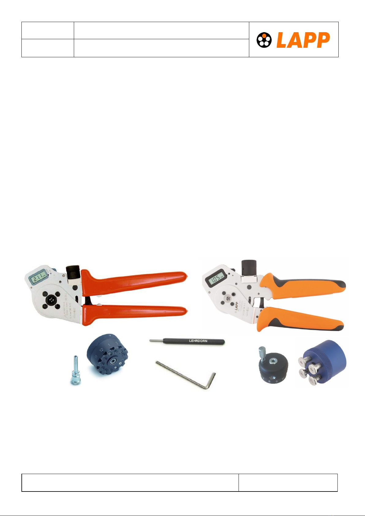
EPIC®CRIMPING TOOL DIGITAL
We reserve all rights according to DIN ISO 16016.
7. Testing calibration to 1.0 mm or 2.0 mm using the gauge
•Check the default setting of your crimper (1.0 mm or 2.0 mm crimp) before use.
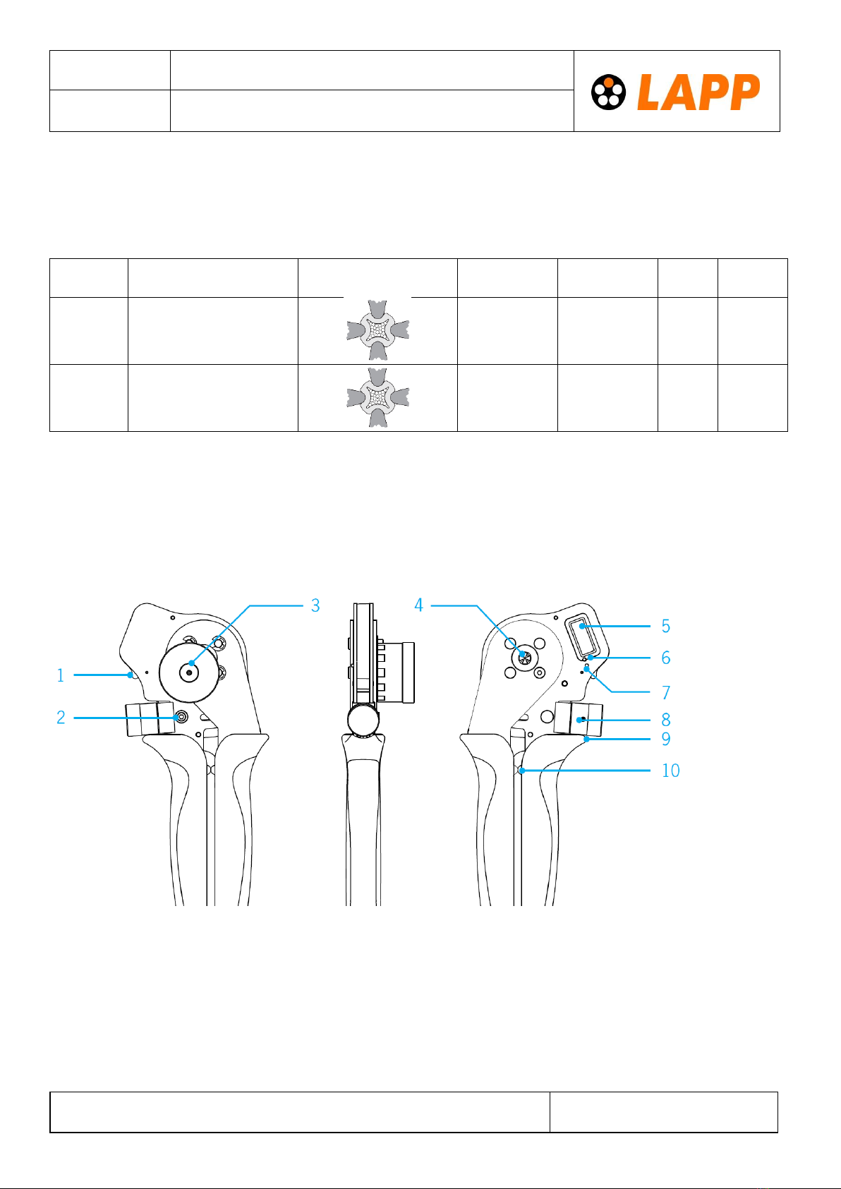
•Switch on your crimper by pressing the ON/OFF switch (7). Set to the default setting (1.0 mm or 2 mm)
using the adjustment wheel (8). Make sure that the gauge measurement is always taken from a larger
value, such as from 1.05 mm down to 1.0 mm or 2.05 mm down to 2.00 mm.
•Close the crimper and place the 1.0 mm or 2.0 mm gauge between the dies. Make sure:
oThat you can move the gauge between the dies without play. If there is no deviation in
measurement, you can use the crimper immediately.
oIf you can move the gauge between the dies with play, or you cannot insert the gauge into the
crimper, you have a deviation in measurement and will need to recalibrate the crimper.
8. Recalibrating the crimper (REC)
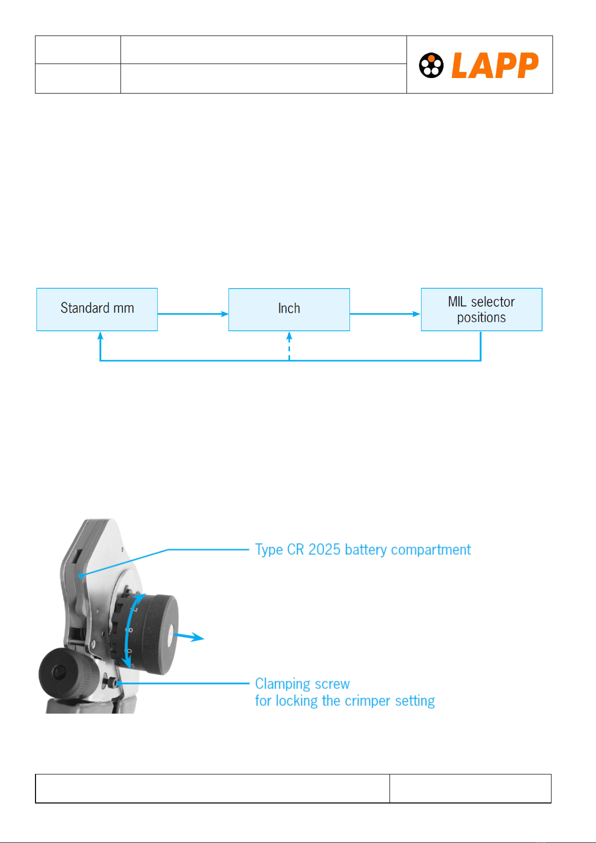
•Set the display to mm using the MODE button (6) (see 2. Operation).
•Set the crimper die using the adjustment wheel (8) until gauge supplied with the crimper touches the dies
and you can move it without play.
•Make sure that the gauge measurement to be set is always taken from a larger value, such as from 1.05 mm
down to 1.0 mm or from 2.05 mm down to 2.0 mm gauge.
•Keep the ON/OFF switch (7) pressed and press the MODE button (6) using the gauge. Keep the MODE
button (6) pressed for at least ive seconds.
•Release the MODE button (6) after ive seconds, and then release the ON/OFF switch (7).
•The digital display will automatically show a gauge value of 1.0 mm or 2.0 mm.
•Your crimper is recalibrated and ready for crimp parameter setting.
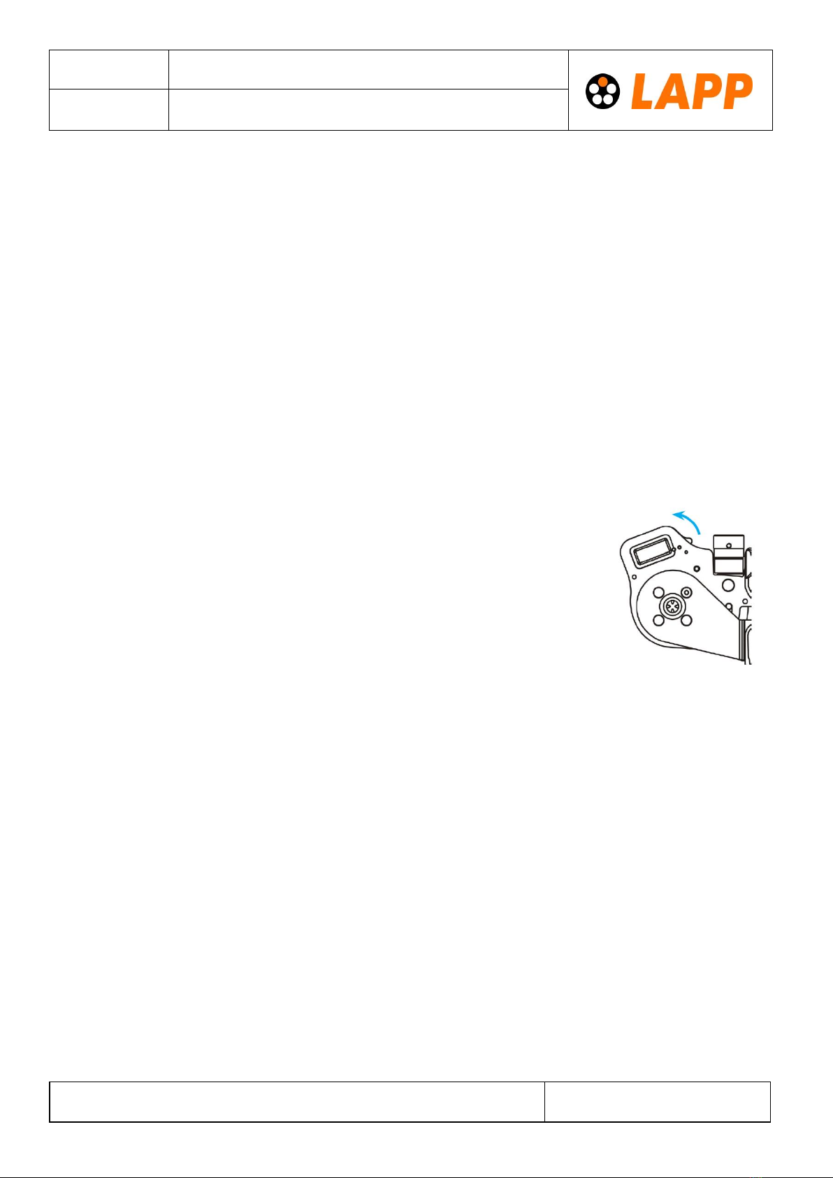
9. Calibrating your tool (CAL) after changing the battery
•Open the battery compartment (1) upwards.
•Remove the used battery.
•Turn the adjustment wheel down to the lower setting (minus sign turning direction) and leave it there.
•Insert the new battery. The display (5) will show CAL as a calibration request.
•Set the crimper to 1.0 mm or 2.0 mm using the gauge –turn the adjustment wheel (8) until you can move
the gauge between the dies without play as shown in 7.
•Keep the ON/OFF button (7) pressed, and press the MODE button (6) with the gauge.
•Make sure that the gauge measurement is always taken from a larger value, such as from 1.05 mm down to
1.0 mm or from 2.05 mm down to 2.0 mm. This means, that at the beginning of the adjustment the gauge
can be inserted with having some play.
•Keep the MODE button pressed for at least five seconds. Release the MODE button after five seconds, and
then release the ON/OFF switch.
•The digital display will automatically show a gauge value of 1.0 mm or 2.0 mm.
•Your crimper is calibrated and ready for crimp parameter setting.