manuals.online logo
Brands
  1. Home
  2. •
  3. Brands
  4. •
  5. Tyco Electronics
  6. •
  7. Crimping Tools
  8. •
  9. Tyco Electronics PRO-CRIMPER III User manual

Tyco Electronics PRO-CRIMPER III User manual

Instruction Sheet
PRO-CRIMPER* III Hand
Tool Assembly 58630-1 408-4453
LOC B
1
of 4
E
2008 Tyco Electronics Corporation, Harrisburg, PA
All International Rights Reserved
TE logo and Tyco Electronics are trademarks.
*Trademark. Other products, logos, and company names used are the property of their respective owners.
TOOLI G ASSISTA CE CE TER 1-800-722-1111
PRODUCT I FORMATIO 1-800-522-6752 This controlled document is subject to change.
For latest revision and Regional Customer Service,
visit our website at
www.tycoelectronics.com
27 AUG 08 Rev A
with Die Assembly 58630-2
PROPER SE G IDELINES
CumulativeTraumaDisorderscanresultfromtheprolongeduse ofmanuallypoweredhandtools.Handtoolsareintendedforoccasionaluseandlowvolume
applications. A wide selection of powered application equipment for extended-use, production operations is available.
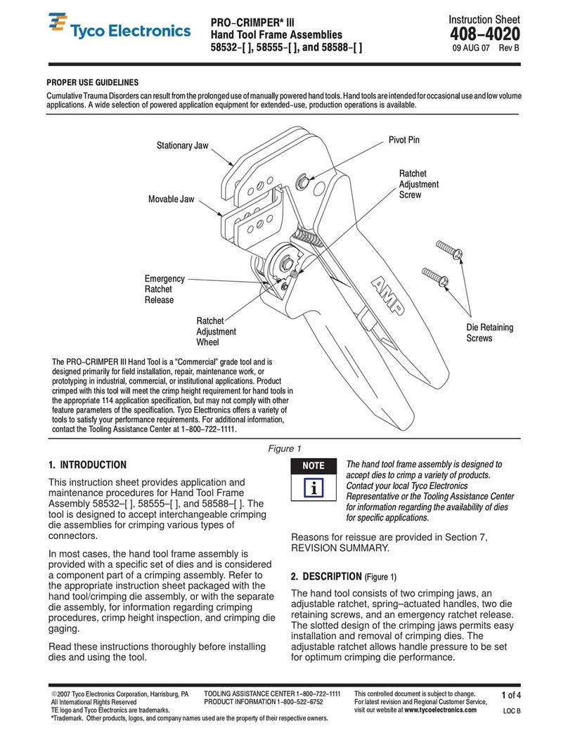
The PRO-CRIMPER III Hand Tool is a Commercial" grade tool and is
designed primarily for field installation, repair, maintenance work, or
prototyping in industrial, commercial, or institutional applications. Product
crimped with this tool will meet the crimp height requirement for hand tools in
the appropriate 114 application specification, but may not comply with other
feature parameters of the specification. Tyco Electronics offers a variety of
tools to satisfy your performance requirements. For additional information,
contact the Tooling Assistance Center at 1-800-722-1111.
Front of Tool
Die Assembly
Moving Jaw
Ratchet Adjustment
Wheel
Moving
Handle
Stationary
Handle
PRO-CRIMPER III Hand
Tool Frame 354940-1 (See
Instruction Sheet 408-9930)
Pivot Pin
Back of Tool
(Wire Side)
Stationary Jaw
DIE ASSEMBLY
PROD CT
WIRE
DIE ASSEMBLY
PART N MBER
PROD CT
FAMILY
}
SIZE
(AWG) INS LATION
DIA MAX STRIP
LENGTH
58630 2
Ultra-Fast FASTO * 12 8.13 7.92+0.41
58630
-
2
Straight Receptacle 10 [.320] [.312+.016]
}
Contact the Tooling Assistance Center at the number listed at the bottom of this page for specific receptacle part numbers.
Figure 1
1. INTROD CTION
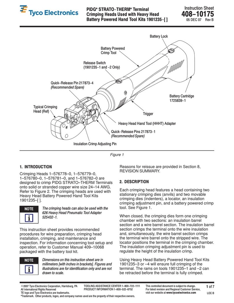
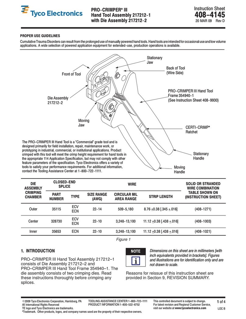
PRO–CRIMPER III Hand Tool Assembly 58630–1
consists of Die Assembly 58630–2 and
PRO–CRIMPER III Hand Tool Frame 354940–1. The
tool is used to crimp the receptacles onto the wire
sizes listed in Figure 1. Read these instructions
thoroughly before crimping any receptacles.
Dimensions on this sheet are in millimeters [with
inch equivalents provided in brackets]. Figures
and illustrations are for reference only and are
not drawn to scale.
2. DESCRIPTION
(Figures 1 and 2)
The tool features a tool frame with a stationary jaw
and handle, a moving jaw, a moving handle, and an
adjustable ratchet that ensures full crimping. The tool
frame holds a die assembly with two crimping
chambers.
The die assembly features an anvil die and a crimper
die. Die retaining pins and die retaining screws are
used to position and secure the dies in the tool
frame.
NOTE
i
408-4453
PRO-CRIMPER III H nd Tool Assembly 58630-1
Rev
A2
of 4 Tyco Electro ics Corporatio
Figure 2
Tool Frame
Die Retai i g
Screws
Crimper Die
Crimpi g Chamber
Wire Size
Marki gs
Die Retai i g Pi
(4 Places)
Chamfer
A vil Die Positio ed
for 12 AWG
Chamfer
A vil Die
Positio ed
for 10 AWG
3. INSTALLATION AND REMOVAL OF
DIE ASSEMBLY
(Figure 2)
1. Open the tool handles and remove the two die
retaining screws from the tool jaws.
2. Place the anvil die in the moving jaw of the tool
frame. The rear crimping chamber is used to crimp
the receptacle—make sure that the wire anvil is
positioned so that the applicable wire size marking
on the die is located at the inside of the frame.
The anvil die is reversible to accommodate wire
size 12 or 10 AWG.
3. Insert die retaining screw and two die retaining
pins through the jaw and into the die. Tighten the
screw just enough to hold the die in place. Do
not
tighten the screw completely at this time.
4. Place the crimper die in the stationary jaw of the
tool frame. Make sure that the chamfered edge of
the die faces outward.
5. Insert die retaining screw and two die retaining
pins through the jaw and into the die. Tighten the
screw just enough to hold the die in place. Do
not
tighten the screw completely at this time.
6. Carefully close the tool handles, making sure
that the anvil and crimper dies align properly.
Continue closing the tool handles until the tool
frame ratchet has engaged sufficiently to hold the
dies in place, then tighten both die retaining
screws.
7. To disassemble, open the tool handles, remove
the two die retaining screws and four die retaining
pins, and slide the dies out of the tool jaws.
4. CRIMPING PROCEDURE
Initially, the crimpin chambers and tool ratchet
should be inspected as specified in Section 5,
CRIMP HEIGHT INSPECTION, and Section 6,
CRIMP HEIGHT ADJUSTMENT, to verify
reliability before usin the tool.
Refer to Figure 1 and select wire of the specified size.
Strip the wire to the length indicated, taking care not
to nick or cut wire strands. Select an applicable
receptacle and identify the appropriate crimping
chamber according to the wire size markings on the
anvil die. Refer to Figure 3 and proceed as follows:
1. Squeeze tool handles together until the ratchet
releases and then allow the tool jaws to open fully.
2. Insert the receptacle (mating end first) into the
BACK of the tool in the
rear
crimping chamber so
that the flat side of the receptacle faces the anvil
die. Make sure that the wire barrel is centered in
the crimping chamber.
3. Hold the receptacle in position and squeeze the
tool handles together until ratchet engages
sufficiently to hold the receptacle in position. Do
NOT deform the wire barrel.
4. Insert the stripped wire into the wire barrel of the
receptacle.
5. Holding the wire in place, squeeze tool handles
together until ratchet releases. Allow tool handles
to open and remove crimped receptacle.
6. Inspect the crimped receptacle to ensure that
the crimp is centered on the wire barrel and the
wire is fully inserted. Check the receptacle crimp
height as described in Section 5. If necessary,
adjust the crimp height as described in Section 6.
NOTE
i
NOTE
i
408-4453
PRO-CRIMPER III Hand Tool Assembly 58630-1
3
of 4Rev
A
Tyco Electronics Corporation
Figure 3
Back of Tool
Crimping
Chamber Strip Length
Anvil Die
Crimper Die
Wire
5. CRIMP HEIGHT INSPECTION
This inspection requires the use of a plug gage
conforming to the dimensions provided in Figure 4.
Tyco Electronics does not manufacture or market
these gages. To gage the crimping chambers,
proceed as follows:
1. Remove traces of oil or dirt from crimping
chambers and plug gages.
GO Dim.
Suggested Plug Gage Design
NO-GO Dim.
25.4 [1.00
Min Typ
CRIMPING GAGE ELEMENT DIMENSIONS (mm [in. )
CRIMPING
CHAMBER GO NO-GO
12 2.3622-2.3698
[.0930-.0933 2.4613-2.4638
[.0969-.0970
10 2.4892-2.4968
[.0980-.0983 2.5883-2.5908
[.1019-.1020
ÉÉ
ÉÉ
ÉÉ
ÉÉ
ÉÉ
ÉÉ
ÉÉ
ÉÉ
ÉÉ
ÉÉ
ÉÉ
ÉÉ
Crimping
Chamber
GO
Element NO-GO
Element
Figure 4
NOTE:
The die anvil must be rotated 180
°
to gage
the opposite nest.
2. Close the tool handles until it is evident that the
dies have bottomed; hold the tool in this position.
Do NOT force the dies beyond initial contact.
3. Carefully insert GO element straight into the
corresponding crimping chamber; do not force it.
The GO element must pass completely through the
crimping chamber. See Figure 4.
4. In the same manner, try to insert the NO–GO
element into the same crimping chamber. The
NO–GO element may start entry, but must not
pass completely through the crimping chamber.
If the crimping chambers conform to the gage
inspection, they are considered dimensionally correct,
and should be lubricated with a THIN coat of any
good SAE 20 motor oil. If not, the tool must be
adjusted according to Section 6, CRIMP HEIGHT
ADJUSTMENT.
For additional information concerning the use of plug
gages, refer to Instruction Sheet 408–7424.
6. CRIMP HEIGHT ADJUSTMENT
(Figure 5)
1. Remove the lockscrew from the ratchet
adjustment wheel.
2. With a screwdriver, adjust the ratchet wheel
from the front of the tool.
3. Observe the ratchet adjustment wheel. If a
tighter crimp is required, rotate the adjustment
wheel
counterclockwise
to a higher–numbered
setting. If a looser crimp is required, rotate the
adjustment wheel
clockwise
to a lower–numbered
setting.
4. Re–assemble the lockscrew.
408-4453
PRO-CRIMPER III Hand Tool Assem ly 58630-1
Rev
A4
of 4 Tyco Electronics Corporation
5. Make a sample crimp and measure the crimp
height. If the dimension is acceptable, the
adjustment setting is correct. If the dimension is
unacceptable, continue to adjust the ratchet, and
again measure a sample crimp.
Screwdriver
Ratchet
Adjustment
Wheel
Lockscrew
Figure 5
7. MAINTENANCE AND INSPECTION
7.1. Maintenance
Ensure that the tool and dies are clean by wiping
them with a clean, soft cloth. Remove any debris with
a clean, soft brush. Do not use objects that could
damage the tool. When not in use, keep handles
closed to prevent objects from becoming lodged in
the crimping dies, and store in a clean, dry area.
7.2. Visual Inspection
The crimping dies should be inspected on a regular
basis to ensure that they have not become worn or
damaged. Inspect the crimping sections for flattened,
chipped, worn, or broken areas. If damage or
abnormal wear is evident, the tool must be replaced.
See Section 8, REPLACEMENT.
8. REPLACEMENT
Customer–replaceable parts are shown in Figure 1.
Available separately, PRO–CRIMPER III Repair Kit
679221–1 includes a replacement nut and a variety of
pins, rings, screws, and springs. If the dies are
damaged or worn excessively, they must be replaced.
Order the repair kit and replaceable parts through
your Tyco Electronics Representative, or call
1–800–526–5142, or send a facsimile of your
purchase order to 717–986–7605, or write to:
CUSTOMER SERVICE (38–35)
TYCO ELECTRONICS CORPORATION
PO BOX 3608
HARRISBURG, PA 17105–3608
9. REVISION SUMMARY
S
Updated document to corporate requirements
S
Changed die artwork in Figures 1, 2, and 3
S
Added callouts to Figure 2
S
Added NOTE to Figure 4

This manual suits for next models

2

Other Tyco Electronics Crimping Tools manuals
Tyco Electronics PRO-CRIMPER III User manual
Tyco Electronics

Tyco Electronics PRO-CRIMPER III User manual

Tyco Electronics PRO-CRIMPER III 58603-1 User manual

Tyco Electronics

Tyco Electronics PRO-CRIMPER III 58603-1 User manual

Tyco Electronics 58605-1 User manual

Tyco Electronics

Tyco Electronics 58605-1 User manual

Tyco Electronics 2-1579004-9 User manual

Tyco Electronics

Tyco Electronics 2-1579004-9 User manual

Tyco Electronics PRO-CRIMPER III User manual

Tyco Electronics

Tyco Electronics PRO-CRIMPER III User manual

Tyco Electronics 58649-1 User manual

Tyco Electronics

Tyco Electronics 58649-1 User manual
Tyco Electronics ERGOCRIMP 2-1579021-9 User manual

Tyco Electronics

Tyco Electronics ERGOCRIMP 2-1579021-9 User manual

Tyco Electronics 1-1579001-2 User manual

Tyco Electronics

Tyco Electronics 1-1579001-2 User manual

Tyco Electronics PRO CRIMPER III User manual

Tyco Electronics

Tyco Electronics PRO CRIMPER III User manual

Tyco Electronics ROTA-CRIMP 68321-1 User manual

Tyco Electronics

Tyco Electronics ROTA-CRIMP 68321-1 User manual

Tyco Electronics 696675-1 User manual

Tyco Electronics

Tyco Electronics 696675-1 User manual

Tyco Electronics PRO-CRIMPER III User manual
Tyco Electronics

Tyco Electronics PRO-CRIMPER III User manual

Tyco Electronics 2063811-1 User manual

Tyco Electronics

Tyco Electronics 2063811-1 User manual

Tyco Electronics STRATO-THERM 1-46673-0 User manual

Tyco Electronics

Tyco Electronics STRATO-THERM 1-46673-0 User manual

Tyco Electronics AMP CERTI-CRIMP II User manual

Tyco Electronics

Tyco Electronics AMP CERTI-CRIMP II User manual

Tyco Electronics 69067 User manual

Tyco Electronics

Tyco Electronics 69067 User manual
Tyco Electronics 408-10050 User manual

Tyco Electronics

Tyco Electronics 408-10050 User manual

Tyco Electronics SIMEL Autocoup CC040 Cof. + charg. User manual

Tyco Electronics

Tyco Electronics SIMEL Autocoup CC040 Cof. + charg. User manual

Tyco Electronics AMP 91907 User manual

Tyco Electronics

Tyco Electronics AMP 91907 User manual

Tyco Electronics PIDG Series User manual

Tyco Electronics

Tyco Electronics PIDG Series User manual

Tyco Electronics PRO-CRIMPER III User manual

Tyco Electronics

Tyco Electronics PRO-CRIMPER III User manual

Tyco Electronics 1804834-1 User manual

Tyco Electronics

Tyco Electronics 1804834-1 User manual

Tyco Electronics PRO-CRIMPER III User manual

Tyco Electronics

Tyco Electronics PRO-CRIMPER III User manual
Tyco Electronics 58593-1 User manual

Tyco Electronics

Tyco Electronics 58593-1 User manual

Popular Crimping Tools manuals by other brands

RIDGID RP 330-B operating instructions

RIDGID

RIDGID RP 330-B operating instructions

Emerson Klauke EK 135FTCFB manual

Emerson

Emerson Klauke EK 135FTCFB manual

Schleuniger UniCrimp 208 operating manual

Schleuniger

Schleuniger UniCrimp 208 operating manual

Hilti NCR 060C-A22 Original operating instructions

Hilti

Hilti NCR 060C-A22 Original operating instructions

Sawyer 260 manual

Sawyer

Sawyer 260 manual

Deutsch HDT-48-00 instructions

Deutsch

Deutsch HDT-48-00 instructions

Hilti NURON NCR 60 D-22 Original operating instructions

Hilti

Hilti NURON NCR 60 D-22 Original operating instructions

BARTON TOOLS HHYD-400 D instruction manual

BARTON TOOLS

BARTON TOOLS HHYD-400 D instruction manual

DMC AFM8 instructions

DMC

DMC AFM8 instructions

molex 207129 Series Specification sheet
molex

molex 207129 Series Specification sheet

molex 207129 Series specification

molex

molex 207129 Series specification

Greenlee GATOR EK622PLX Operation manual

Greenlee

Greenlee GATOR EK622PLX Operation manual

BEX MultiBEX mx4 instruction manual

BEX

BEX MultiBEX mx4 instruction manual

molex 63823-7570 Specification sheet

molex

molex 63823-7570 Specification sheet

TE Connectivity 2063490-1 instruction sheet

TE Connectivity

TE Connectivity 2063490-1 instruction sheet

Staubli CT-CP Assembly instructions

Staubli

Staubli CT-CP Assembly instructions

Herth+Buss ELPARTS CrimPro HV Operating	 instruction

Herth+Buss

Herth+Buss ELPARTS CrimPro HV Operating instruction

TE Connectivity PRO-CRIMPER III instruction sheet

TE Connectivity

TE Connectivity PRO-CRIMPER III instruction sheet

manuals.online logo
manuals.online logoBrands
  • About & Mission
  • Contact us
  • Privacy Policy
  • Terms and Conditions

Copyright 2025 Manuals.Online. All Rights Reserved.