Lasermet IS-MDC-12 User manual

IS-MDC-12 Instruction Manual
CEB00249-53-000 Issue 3 19 January 2021
LASERMET IS-MDC-12
INSTRUCTION MANUAL
CODED DUAL CHANNEL MAGNETIC
DOOR CONTACT

IS-MDC-12 Instruction Manual
CEB00249-53-000 Page 2 of 12 Issue 3 19 January 2021
LASERMET IS-MDC-12
Instruction Manual
Contents
1 Declaration of Conformity .............................................................................................................. 3
2 Safety Warnings .............................................................................................................................. 4
3 Concept ........................................................................................................................................... 5
4 Summary of Evaluation of Compliance to EN ISO 13849-1:2015 ................................................... 5
5 Installation ...................................................................................................................................... 6
5.1 Testing Using a Multimeter ..................................................................................................... 8
5.2 Electrical Connections ............................................................................................................. 8
5.3 Final Testing ............................................................................................................................ 9
6 Specifications ................................................................................................................................ 10
7 Warranty ....................................................................................................................................... 11
8 Contact Details .............................................................................................................................. 12

IS-MDC-12 Instruction Manual
CEB00249-53-000 Page 3 of 12 Issue 3 19 January 2021
1 Declaration of Conformity
LASERMET LIMITED
CODED MAGNETIC DOOR CONTACT
Part no. IS-MDC-12
DECLARATION OF CONFORMITY
This is to certify that the Coded Magnetic Door Contact designated by Lasermet Part
Number IS-MDC-12 has been tested in accordance with the following directives and
standards and found to comply.
Lasermet certifies that this product complies with the basic requirements for health
and safety as provided by the following directives and standards:
Directives: Machinery Directive 2006/42/EC
Relevant parts of Low Voltage Directive 2014/35/EU
Standards: EN ISO 13849-1:2015
Safety of Machinery – Safety-related parts of Control Systems
EN ISO 60947-5-3:2013
Low Voltage Switchgear and Control
BS EN ISO 14119:2013
Safety of Machinery – Interlocking Devices associated with Guards
Supplier:
Lasermet Limited
Lasermet House
137 Hankinson Road
Bournemouth
BH9 1HR
Dorset
United Kingdom
Country of Origin: England
Date: 10 June 2019

IS-MDC-12 Instruction Manual
CEB00249-53-000 Page 4 of 12 Issue 3 19 January 2021
2 Safety Warnings
This device is intended to be used as part of a safety system which may be used to protect personnel
and equipment from possible injury, damage, or loss.
As such it must be installed and wired according to these instructions and tested by suitably qualified
persons. No attempt may be made to tamper with the parts, open them, or use them outside of the
parameters contained herein.
The units are only designed to be fixed to surfaces using their inbuilt fixing holes. They must not
come into contact with each other or any other moving part when in use. The parts should never be
subject to impact or mechanical strain.
Safety switches should never be defeated or bypassed. It is imperative that all steps are taken to
ensure that any spare actuators are made unavailable, such that they cannot be used to defeat the
switch or reduce the protection offered by the system in any way.

IS-MDC-12 Instruction Manual
CEB00249-53-000 Page 5 of 12 Issue 3 19 January 2021
3 Concept
The Lasermet IS-MDC-12 is a dual channel coded magnetic door safety contact. It is ideal for use in
conjunction with Lasermet’s ICS range of laser interlock controllers as part of a safety interlock
system.
It is used to detect when a door or other moveable cover forming part of a protective enclosure is
open. The IS-MDC-12 features three contacts, two of which are closed and one of which is open
when the door is closed. All three contacts change over when the door is open.
The IS-MDC-12 can achieve Performance Level ‘e’ as specified in EN ISO 13849-1:2015 when
correctly wired to a suitable interlock controller such as Lasermet’s ICS-6.
4 Summary of Evaluation of Compliance to EN ISO 13849-1:2015
To achieve a complete system performance level ‘e’ the system must be wired as described in this
manual using suitably rated door sensors and measures taken to minimise the effects of common
cause failures in the sensors and wiring which may be connected to the unit.
Achieved Characteristics:
Architecture Category 4
Performance Level (PL) PL = e 1
PFH [1/h] 3.68 x 10⁻⁸
MTTFd 100 years
Mission Time 20 years
Application Demand Base:
In service operation 365 days/year
Functional demand on the interlock switch 8 per day
1 The level of performance assessed is based on the typical application demand resulting from the B10d values of the
internal components based on a maximum usage rate of 2920 operations per year.

IS-MDC-12 Instruction Manual
CEB00249-53-000 Page 6 of 12 Issue 3 19 January 2021
5 Installation
The Door Contact is intended for indoor benign environments. It is not suitable for use in locations
exposed to rain or moisture, in areas of high humidity or corrosion. It is not certified for use in areas
where an explosion hazard exists.
The Door Contact may be fitted to most door and frame materials including wood,
uPVC, steel, aluminium etc.
The Door Contact comprises two parts shown below

IS-MDC-12 Instruction Manual
CEB00249-53-000 Page 7 of 12 Issue 3 19 January 2021
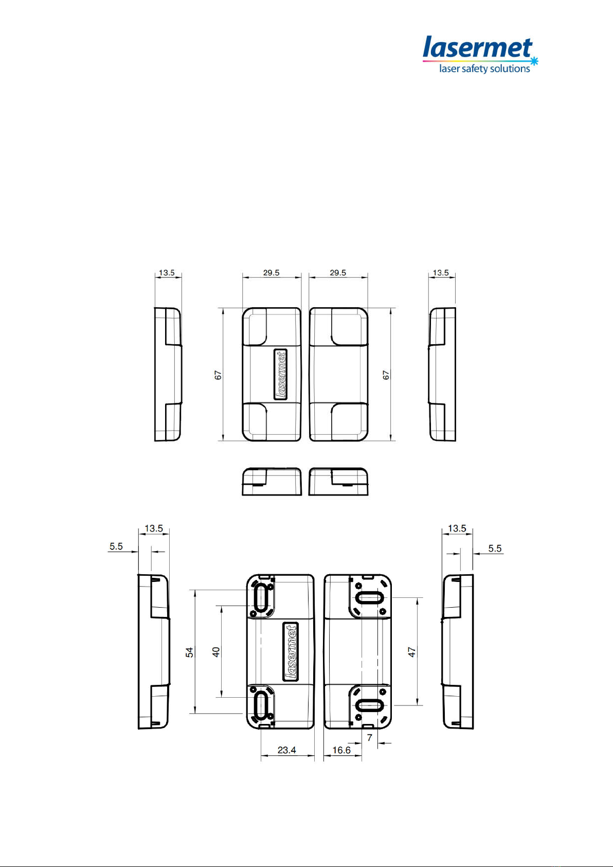
The part with the Lasermet badge and the cable
attached (known as the switch) is normally affixed to
the door frame, and the other part (known as the
actuator) is attached to the door. The fixing hole
positions are shown above and the usual mounting
arrangement on a door on the left.
It is usual to site the units close to the opening side of
the door so that even a slight opening is detected. It
is also usually preferable to position the units in the
most inaccessible position to discourage tampering.
By default, the lead of the switch unit exits at the
back. It is visually preferable if a hole can be drilled
into the architrave such that the lead can be hidden
out of sight. The lead may then be buried in the wall
or taken into mini trunking adjacent to the architrave.
If this is not possible the side of the switch body
adjacent to the lead may be carefully broken out to
allow the lead to run along the surface. Take care not
to damage the lead when making the breakout.
On some doors the door surround (architrave)
projects forward of the door face. The IS-MDC-12 will
work with the switch unit up to 8mm or more in front
of the actuator unit, as shown in the figure. This may
reduce or eliminate the need for cutting into the
architrave.
Some experimentation using temporary means of
attachment may be useful to determine the optimum
position, see the section, ‘Testing with a Multimeter’.
Fit the two parts to the door using the screws
provided, but do not tighten the screws fully or fit the
screw caps until the system has been completely
tested. The two long flat sides of the units should
face and be aligned with each other. The gap
between the units should be in the range 1mm –
5mm.
The screw holes in the two parts are slotted to allow
for adjustment and alignment. If the lead has been fed into a hole behind the switch part, the hole
may need to be adjusted to allow for any repositioning of the switch. It is suggested that the screw
covers are not fitted until the switch has been tested, as they may get accidentally broken if
subsequently removed.

IS-MDC-12 Instruction Manual
CEB00249-53-000 Page 8 of 12 Issue 3 19 January 2021
5.1 Testing Using a Multimeter
The contact can be tested for correct operation using a multimeter before it is wired to the interlock
panel. To do this set the meter to the continuity buzzer mode and check that it bleeps when the
probes are touched together.
Next attach one probe to the red wire of the door contact and the other to the blue wire. When the
door is closed the buzzer should sound. Repeat for the black and white wires.
Lastly check the green and yellow wires. With these wires the buzzer should only sound when the
door is open. Check that all three pairs of contacts work correctly under all conditions of door
movement. For example, with the door held shut by its catch or lock, check that the contacts work
as above without interruption when the door is pushed against the jamb and pulled against its lock.
5.2 Electrical Connections
Lead Core Colours
In this manual a ‘normally closed’ contact is one which is made when the door is closed, and a
‘normally open’ contact is made when the door is open.
Red-Blue Normally Closed Contact 1
White-Black Normally Closed Contact 2
Yellow-Green Normally Open Contact
Contact Rating
All three contacts in the switch are isolated from each other and rated at 50V 300mA resistive load.
On no account must mains/line voltage be applied to this product.
The load current should never exceed 300mA and the switch has internal overcurrent protection
which will disable it permanently should this current be exceeded. If this happens the switch should
be replaced. The switch should never be opened. This will invalidate the warranty and there are no
serviceable parts inside.
All Lasermet ICS panels comply with this requirement.
Wiring to a Lasermet ICS Interlock Control Panel
ICS-6
Select an unused Interlock connector J1-J4.
Connect the red wire to an A terminal.
Connect the white wire to a B terminal.
Connect the black wire to the other B terminal.
Connect the blue wire to the other A terminal.
The green and yellow wires are not used on the ICS-6.

IS-MDC-12 Instruction Manual
CEB00249-53-000 Page 9 of 12 Issue 3 19 January 2021
Extending the Lead
The lead fitted to the door switch is usually not long enough to reach the control panel and will need
to be extended using low voltage stranded multicore cable. Unless the cable run is exceptionally
long, cable with 7/0.2mm cores are suitable. Six core cable is required unless connecting to an ICS-6,
where only four cores are necessary. Lasermet can supply suitable cable to match that fitted to the
switch.
5.3 Final Testing
Once the panel is fully wired the system may be tested according to the ICS instruction manual or
specific instruction procedures.
The final position of the switch should be adjusted so that the system is disabled before the door or
cover is sufficiently opened to present a hazard to those outside.
Once the final position of the switch and actuator have been set, they may be secured by fully
tightening the screws. The screw caps should then be fitted to cover them. Note that all four caps
are different, and care should be taken to fit the right ones in the right places.

IS-MDC-12 Instruction Manual
CEB00249-53-000 Page 10 of 12 Issue 3 19 January 2021
6 Specifications
Contacts 2NC / 1NO
Rating 300mA Resistive Load 50V
Channels 2, dual channel
Magnet Coupling Coded
Maximum Range 10mm typical
Safety Performance Up to BS EN 13849-1:2008 PL ‘e’
Operating Environment -5° to +45°C, 0 – 95% RH
Environmental Protection IP50
Switch Size 67 X 29.5 X 13.5mm
Actuator Size 67 X 29.5 X 13.5mm
Lead Length 1m approx.
Combined weight 85g approx.
Safety Performance
This product is certified to Performance Level ‘e’ (PLe) to EN ISO 13849-1:2015.
When connected to an interlock control system as shown in this manual, the IS-MDC-12 has the
following characteristics. This can also be achieved by correctly connecting to another suitable safety
control system which has dual channel monitoring of the shutdown device.
Mean time to dangerous failure (MTTFd) 100 years
Probability of dangerous failure per hour (PFH) 3.68 x 10⁻⁸
It is important to note that the Performance Level established for the IS-MDC-12 are those that may
be achieved by the system when the board is properly integrated into a safety related part of a
control system.

IS-MDC-12 Instruction Manual
CEB00249-53-000 Page 11 of 12 Issue 3 19 January 2021
7 Warranty
Lasermet provide a 12-month warranty for defects in materials and manufacture, from the date of
installation or delivery. Installations completed by Lasermet are covered against defects in
workmanship for 12 months.
Damage or defects caused by other factors are not covered. For example, industrial contamination,
incorrect cleaning, storm damage. Consequential loss is not covered under warranty. Compensation
for indirect or direct loss or damage is expressly excluded. Rectification of the defects or a
replacement does not initiate a new warranty period.
For all deliveries, payments and other legal transactions, English law takes precedence for any
litigation.

IS-MDC-12 Instruction Manual
CEB00249-53-000 Page 12 of 12 Issue 3 19 January 2021
8 Contact Details
Lasermet provide a full range of laser interlock equipment including interlock switches, illuminated
warning signs, laser shutters, entry keypads with built-in fail-safe override timer, door locks, external
power supplies etc. which can be interconnected to provide a complete system. We also supply
equipment and consultancy covering all aspects of laser safety. Full support, design, and installation
is available from Lasermet, please contact us for any queries.
For sales and technical support:
Lasermet Ltd.
Lasermet House,
137 Hankinson Road,
Bournemouth
BH9 1HR
United Kingdom.
Tel: +44 (0) 1202 770740
Fax: +44 (0) 1202 770730
Website: www.lasermet.com
Lasermet Inc.
10N Martingale Road, Suite 400,
Schaumburg, Illinois 60173
United States.
Tel: 847 466 1475
Website: www.lasermet.com
Table of contents
Other Lasermet Safety Equipment manuals