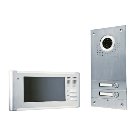
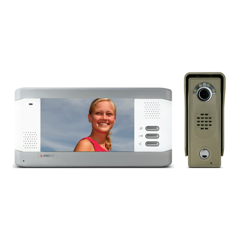
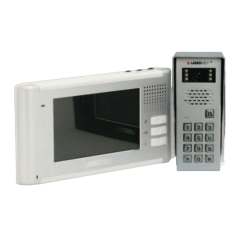
Laskomex Bastion Draco User instructions

Video door phone set
Assembly and operating manual

- 1 -
CONTENTS
1. Operating conditions 2
2. Purpose and characteristics of video door phone 2
3. Elements of Bastion video door phone 2
- MVC-6501 monitor 2
- BVC-6501 external panel 3
- ZS-15 feeder 4
- Electro-catch 4
- Electro-catch feeder 4
4. Before the assembly 5
- Specify the places where elements are to be mounted 5
- Electric installation of video door phone 5
- Block / connection diagrams 6
5. Assembly and connecting elements of video door phone 8
- Assembly and connection MVC-6501 monitor 8
- Assembly and connection the external panel BVC-6501 9
- Feeder assembly 9
- Assembly of electro-catch 9
6. Operating video door phone 9
7. Maintance 10
8. Technical data 10

- 2 -
1. OPERATING CONDITIONS
- Before installing and using the video door phone, read the assembly and operating
manual.
- Electrical installation should be made in accordance with PN-IEC 60364-1 standard
by an authorized person.
- Electrical installation should be made in such a way as to prevent exposure to direct
lightning discharge.
- Video door phone elements should be used as intended. Using video door phone
elements for other purposes, including with equipment other than specified in the
manual or connecting them in other manner than prescribed by the manufacturer may
lead to their damage, fire or electric shock.
- Do not cover the openings in the monitor housings.
- Do not insert any metal items in the openings in the monitor housing and the feeder
as it may lead to electric shock or fire.
- The external panel should be installed in a place with low noise level.
- The external panel is powered with video door phone voltage. +Vcc and GND clamps
on the external panel should not be connected to an external feeder.
- Video door phone elements should be connected to an electrical installation when
the feeder is disconnected from the power network.
2. PURPOSE AND CHARACTERISTICS OF VIDEO DOOR PHONE
- Video door phone is designed for single family houses, companies, institutions and
service providers.
- Two monitors may be connected to the external panel.
- Monitor featured with TFT colour display is used in the video door phone. It is
a hands free duplex monitor (two-way voice communication without manual control
of call direction).
- The external panel is wall-mounted.
- The panel is equipped with a colour camera and a LED display facilitating viewing
visitors faces at night.
For affirmation of safety put on the mains terminal
covering (plastic element attached to the feeder)
after connect the feeder to the mains.
Covering installation method is shown on
drawing. All the connection make with
the power supply turn off.
!
NOTE!

3. ELEMENTS OF BASTION VIDEO DOOR PHONE
MVC-6501 monitor
7'' hands free screen equipped with TFT colour display. It is possible to set screen
brightness, contrast and volume of the monitor. Function buttons allow for door release,
answering calls and launching viewing.
- 3 -
Figure 1. MVC-6501 videomonitor
BVC-6501 external panel
Vandal-proof panel with a colour camera, camera illuminator, loudspeaker, microphone
and release button. The panel is wall-mounted. The panel is equipped with a transmitter
releasing electro-catch after the button on the monitor is used.
Figure 2. MVC-6501 external panel
Camera
Illuminator
Loudspeaker
Button
Microphone
red
+Vcc black
GND white
audio violet
video yellow
electrocatch brown
electrocatch
Transfer conversation
Electric door strike/
end of conversation
Conversation/ screening
LED (Power supply)
Screen
Microphone
Volume ContrastBrightness
Loudspeaker
LED (conversation)

- 4 -
ZS-15 feeder
DCV feeder, 15V DC/800 mA to mount on DIN rail used to power the monitor and
the external panel.
The set is additional featured with:
- Assembly rail
- Assembly screws
- Pins necessary to connect the set
Additional elements not included in the basic set:
Electro-catch (not include in the set)
Electro-catch of 12V AC/1A max. should be used in the video door phone. While
selecting the electro-catch, take into account the mechanical build and type (left or
right) of the door or gate to be blocked. Electro-catch of Openers&Closers company
may be used (technical details at: www.laskomex.com.pl).
Feeder to electro-catch (option - not included in the basic set)
ACV feeder: 12V AC/800 mA to mount on a DIN rail.
Figure 3. ZS-15 DCV feeder
AC
230 V
DC
15V/800mA

- 5 -
4. BEFORE THE ASSEMBLY
Specify the places where video door phone elements are to be mounted.
- Mount the monitor in a place not exposed to strong light (e.g. close to the lamp,
window etc.) as it may obstruct viewing image on the screen.
- Do not mount the monitor in place where it could be exposed to humidity e.g. in
bathrooms.
- Do not mount the monitor near the sources of strong electromagnetic interference
(wiring, TV sets etc.)
- Do not mount the monitor in heating sources - stoves, radiators etc.
- The external panel should be mounted in such a place that the camera lens is not
directed to light source (sun, strong lamp post) because it will significantly obstruct
or prevent viewing the visitors' faces.
- The image on the screen depends on the height the panel is mounted at. The
recommended height is ca. 150 cm Such height allows for viewing the image of the
face of an adult of normal height standing ca. 50 cm from the panel. The assembly
height should be determined on a trial basis.
- Do not mount the external panel at the distance exceeding 60 m from monitor (with
the appropriate cable sections).
- Mount the feeder inside, in a place not exposed to humidity. Feeder should be mounted
on a DIN rail in the electric installation box.
- The above recommendations relate to both the monitor feeder and door strike feeder.
The door strike feeder may be mounted near the external panel (e.g. in the installation
box of fence pillar).
Electric installation of video door phone.
Elements of video door phone may be connected with any cable with section meeting
the requirements specified in Table 1.
At the distances between the monitor and the external panel exceeding 30 m,
a 75 coaxial cable should be used to transmit video signal. The coaxial cable should
be connected as presented in Figure 7.
The maximum distance between the external panel and the monitor should not exceed
60 m.
Table 1. Cable section according to the distance between door phone elements
+Vcc,GND,audio
video
0,4mm2
<15m <30m
0,75mm2
Coaxial cable
<60m
1mm21.5mm22.5mm2
maximum 4m,
Distance
Connection
external panel - monitor
DCV feeder - external monitor
DCV feeder - monitor
DCV feeder - 230V
monitor - monitor
1mm2
0,75mm2
0,75mm2
0,4mm2
0,75mm2

Figure 5. Block diagram of connecting elements of Draco video door phone
- 6 -
BVC-6501
ZS-15
12V AC/1A feeder
Electro-catch
MVC-6501
230V
230V
2
2
2
2
2
4
Figure 4. Connection of Draco video door phone - single line diagram
MVC-6501
ZS-15
2
230V 2
4
Optional - connecting second monitor
MVC-6501
+ -~ ~
BVC-6501
12V AC/1A feeder
ZS-15
J103J100
Electro-catch
Wiring in external panel
+ -
230V AC 15V DC/0.8A
~ ~
230V AC
12V AC/1A
~ ~
+Vcc Gnd audio video
red
black
violet
white
+Vcc Gnd audio video
red
black
violet
white
brown
yellow

- 7 -
Figure 7. Block diagram of connecting elements of Draco video door phone in use
with coaxial cable
+ -~ ~
BVC-6501
12V AC/1A feeder
ZS-15
J103J100
Electro-catch
Wiring in external panel
J102
+ -~ ~
J100
J102
ZS-15
Figure 6. Block diagram of connecting elements of Draco video door phone with
additional monitor
MVC-6501
MVC-6501
+ -
230V AC 15V DC/0.8A
~ ~
230V AC
12V AC/1A
~ ~
+Vcc Gnd audio video
red
black
violet
white
+Vcc Gnd audio video
red
black
violet
white
+Vcc Gnd audio video
red
black
violet
white
+Vcc Gnd audio video
red
black
violet
white
-
230V AC 15V DC/0.8A
+
Electro-catch
BVC-6501
12V AC/1A feeder
ZS-15
J103J100
Wiring in external panel
MVC-6501
+ -
230V AC 15V DC/0.8A
~ ~
230V AC
12V AC/1A
~ ~
+Vcc Gnd audio video
red
black
violet
white
+Vcc Gnd audio video
red
black
violet
white
+ -~ ~
brown
yellow
brown
yellow

- 8 -
5. ASSEMBLY AND CONNECTING ELEMENTS OF VIDEO DOOR
PHONE
Assembly and connecting MVC-6501 monitor
To facilitate the assembly, mount a standard cable box in the wall where the monitor
is to be mounted and insert the wiring of the video door phone. After the assembly,
the monitor should wholly cover the cable box. This will facilitate connecting and
mounting the monitor.
- The monitor is mounted on a metal grip screwed to the wall. To mount the grip, put
it at the wall where it is planned to be mounted and mark places for dowels.
- Drill openings in the marked places and mount the grip to the wall using the dowels.
- Connect the plugs (included in the set) for J100 and J103 sockets to the wiring in
accordance with the diagram, soldering them to the wiring. Secure the soldered places
and isolated wiring cables against short circuit using shrink wrap or insulation.
Connect the plugs to the sockets.
- Mount the monitor at the assembly jig.
Connecting an additional monitor
- In order to connect two MVC-6501 monitors to one external panel, power supply
(J100 socket) should be disconnected in the additional monitor and the two monitors
should be connected using J102 sockets. J103 socket in the second monitor is not
used. See Figures 4 and 6.
Figure 8. Connectors in MVC-6501 monitor
Pin to J100 socket
(power supply)
Pin to J103 socket
Pin to J102 socket
(optional)
J100
J102 J103
red
+Vcc
black
Gnd
red
+Vcc
black
Gnd
white
audio
violet
video
red
+Vcc
black
Gnd
white
audio
violet
video

- 9 -
Feeder assembly
The feeder is designed for mounting on a DIN rail. The feeder may be mounted in the
installation box with a DIN rail or on a metal grip previously screwed to the wall with
dowels (included in the set). Connect the wires in accordance with the diagram.
Assembly of electro-catch
Electro-catch is controlled by a transmitter located in the external panel. The electro-
catch requires an additional ACV feeder. Mount the electro-catch in the gate or the
door as prescribed by the manufacturer. Then, in accordance with the diagram (Figures
5,6,7) connect the wires (yellow and brown) in the external panel, feeder wires and
electro-catch.
Figure 9. Assembly of external panel
6. OPERATING VIDEO DOOR PHONE
- By pushing the release button in the gate phone, the doorbell signal in the monitor
will be activated and the monitor will switch on, displaying image from the camera.
If an additional monitor is mounted the doorbell signal and the image from the camera
will appear on two monitors.
- Push button (conversation - see Figure 1) to launch voice communication. In the
case of two monitors mounted, once the voice communication is launched on one
screen, the other monitor switches off.
- The conversation may last up to ca. 100s. After this time, the conversation is
automatically ended.
Assembly and connecting the external panel.
- Twist off the screw mounting the panel and the housing
- Put the housing in the assembly place, mark places and drill openings for dowels.
The camera lens should be located at the height of ca. 150 cm (see Figure 9a).
- Put the wire through the round opening in the housing and mount the housing to the
wall (Figure 9c).
- Connect the wires in accordance with the diagram. A cable with colour wires (see
Figures 2 and 5) is located in the gate phone. Connect those wires with the wiring
of the video door phone using a soldering iron, protecting the joint with shrink wrap
or insulation.
- Put the panel to the housing and screw the assembly screws (Figure 9d).
a) b c) d
150 cm
- 10 -
7. MAINTENANCE
Video door phone elements should be cleaned with a damp duster. Alternatively, use
preparations for plastic elements cleaning.
ATTENTION!
Do not use preparations including solvents or abrasive materials to clean the video
door phone elements, as their use may lead to permanent damage of the housing
surface! Avoid letting the video door phone elements contact with water or detergents
during cleaning as it may lead to the damage of video door phone.
8. TECHNICAL DATA
MVC-6501 monitor
Screen size 7
Dimension 240x175x35
Supply voltage 15V DC/0.8A
Operation temperature 0°C...70°C
BVC-6501 external panel
Dimension 135x55x40
Operation temperature -20°C...70°C
ZS-15 feeder
Input voltage 230V AC
Output voltage 15V DC/ 800 mA max.
Dimension 87x87x60
Operation temperature 0°C...70°C
- It is possible to release the electro-catch at any time during the conversation by
pushing the button on the screen. The electro-catch operates for up to ca. 5 s. Its
operation period does not depend on the length of button pushing. The electro-catch
is activated once the button is released.
- To close the conversation push (conversation) button.
- Should the voice communication after launching fail to activate, the monitor will be
automatically switched off after ca. 1 minute.
- The image from the camera may be activated on the screen at any time. In order to
do so push (conversation) button.
- It is possible to set volume, contrast and brightness on the MVC-6501 monitor (see
Figure 1)
Operating video door phone with additional monitor
- Pushing the transfer conversation button during the voice communication will
transfer the conversation to the second monitor - the first monitor switches off, and
on the second monitor the doorbell sounds and the image from the camera is shown
(no audio mode).
- In order to receive the transferred conversation push (conversation) button.

This product was marked with a symbol of crossed dustbin
according to European Directive 2002/96/WE on used electric
and electronic equipment. Used equipment cannot be placed
with other wastes from households. Product user is obliged to
give it to the firm which collects used electronic or electric
equipment such as local collection points, shops, places appointed
by the producer or commune waste collection units.
INSTRUCTION ON ENVIRONMENT PROTECTION
List of collecting units of used Laskomex equipment is available on
www.laskomex.com.pl website or telephone No. 42 671 88 68.
Product packing should be removed according to environment protection regulations.
Remember!
Selective collection and recycling of used electronic and electric equipment
considerably contributes to the protection of human health and life as well as
protection of natural environment.
Return of packaging materials for the material recycling saves raw materials and
reduces generating of wastes.
ver 1.2 2008-09-02
Table of contents
Other Laskomex Intercom System manuals

Laskomex
Laskomex CD-2000 Installation manual

Laskomex
Laskomex Bastion Draco II User manual

Laskomex
Laskomex EC-2502 Owner's manual

Laskomex
Laskomex CD-2000 Installation manual

Laskomex
Laskomex CD-3100 Series Installation manual

Laskomex
Laskomex Bastion Apus User manual

Laskomex
Laskomex Bastion Orion II User manual

Laskomex
Laskomex Bastion libra User instructions

Laskomex
Laskomex Bastion Apus II User manual

Laskomex
Laskomex CP-2502 Series User manual