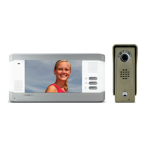
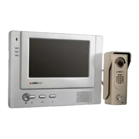
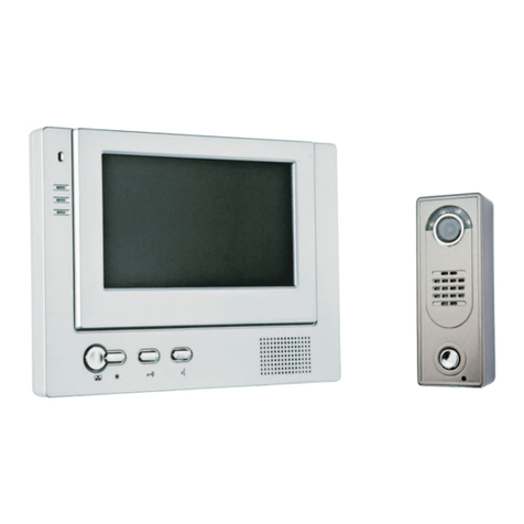
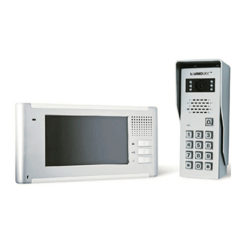
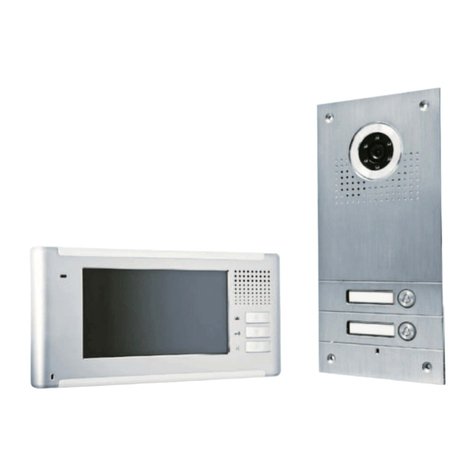
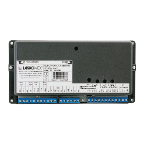
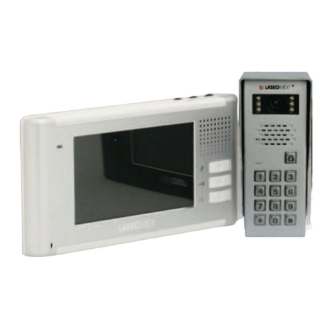
Laskomex CP-2502 Series User manual

INSTALLATION OF PANELS
CP-2502xxx
CD-2503xxx
CP-2510xxx
CP-2513xxx
CP-2511xxx
CP-2520xxx
CP-2523xxx
CP-2521xxx
CP-2530xxx
CP-2533xxx
DIGITAL ENTRY PHONE SYSTEM
CP-2530, CP-2533
CP-2520, CP-2523
CP-2510, CP-2513 CP-2502, CP-2503

Page 2
CP-2502
/
2503/2510
/
2511/2513
/
2520
/
2521/2523/2530/2533
LASKOMEX PPUH, ul. D¹browskiego 249, 93-231 £ód, tel. (42) 671 88 00, fax (42) 671 88 88, e-mail: [email protected], http://www.laskomex.com.pl
1. SAFETY AND USAGE CONDITIONS
- Prior to the installation please read the following instruction.
- Electric installation should be done in accordance with PN-IEC-60364-1 norm by the
authorized person. Installation should not be directly exposed to atmospheric electrostatic
discharge.
- It is forbidden to connect the panel to other installations, with exception of the application
recommended by the producer.
- Self maintenance is only permitted for qualified persons. Device maintenance by unauthorized
persons may result in the lost of warranty.
- It is forbidden to connect power supply from sources with different parameters than
recommended by the producer to panel clamps. The producer is not responsible for any
lost occurred due the usage of improper power supplies.
- Signals from the digital entry phone system should not be directly connected to RTV sets,
because of risk of devices and system damages.
- View distortions occurred when raining or just after rain are temporary, they are associated
with water gathering near camera lens and should not be perceived as symptom of device
damage.
- Outdoor panel should not be sealed (i.e silicon), cause it worsens ventilation and leads to
corrosion.
- Dirt on the keyboard (snow, mud) may cause faulty operation - in such case dirt should be
immediately removed.
- Do not clean the panel with gasoline, solvents or strong detergents as it may cause damage
of the device surface.
2. OUTDOOR PANEL ASSEMBLY
Panel installation can only be carried out when power supply is off !
If possible outer panel should be installed inside wind shields as it is better secured
against atmospheric factors.
Lens located in the camera panel must not be pointed directly to strong light source (the
sun, strongly lightened street lamp), cause it may seriously or completely limit observation
of speakers faces.
Panel should be installed on the proper altitude providing comfortable usage of the device
for all users. Suggested altitude is approx. 150 cm. Install the device lower in order to
enable usage for disabled and invalids.
When installing panels make certain to provide proper ventilation for each unit. For that
reason it is not recommended to seal the space between the frame and the panel with
silicon or foam etc.
When installing panel with the tenants list make certain to write down names before
riveting the device.
Mounting under the plaster.
In the wall cut out an opening of the dimensions that would enable to place the external
panel freely in it and the frame should completely cover the opening edges. Then 4 holes
o 10 mm should be drilled for strut pins. The tightening force (important when the cut out
opening is deeper than depth of cassette) should be matched to avoid bending of a frame.
Make electrical connections and fix panel with a keyboard by two M4 screws and two rivets
(included in the set).
Page 3
CP-2502
/
2503/2510
/
2511/2513
/
2520
/
2521/2523/2530/2533
LASKOMEX PPUH, ul. D¹browskiego 249, 93-231 £ód, tel. (42) 671 88 00, fax (42) 671 88 88, e-mail: [email protected], http://www.laskomex.com.pl
Mounting on the plaster.
Drill openings for mounting the panel casing (mounted on the plaster), place the frame (or
frames) in the casing mounted under the plaster and screw both elements by strut pins.
Connect the wires and fix the panel with keyboard by screws and rivets.
Panel with the tenants list assembly
Description should be done in any graphic program and printed on the paper seize 51x90mm
for CP-2502N panel and 65x60mm for CP-2530 panel. When printing mind the 4mm margin
on every paper edge.
Figure 1: Replacement of a sheet with a list of occupants:
a) in CP-2502N panel,
b) in CP-2530, CP-2533 panels
3. DIGITAL ENTRY PHONE SYSTEM CD-2502 ADJUSTMENT
The elements of entry phone system are preliminarily adjusted and, unless it is necessary,
the position of potentiometers should not be changed.
Figure 2: Position of the potentiometer P4 in the external panel - in CP-2502.
Loosen the mounting
screws and move the
frame towards the outside
edge of a panel
Slide the card with description
in the plate slot
a) b)
Move the frame as
shown on the
drawing and tighten
the screws.
Remove plexi glass
plates
Dents on the frame left
side should be put in the
openings in a casing panel.
The frame should be
pushed so that screws are
inserted in frame openings
Place a sheet of paper
with a description between
the plates and put them
back in a panel
remembering that thin
plate should be placed at
the casing back side
Remove the frame by
lifting it slightly and then
moving towards the
outside edge of a panel
K1
K2
K3
K4
K5
K6
M
J
S
K
D
P4
J
-+

Page 4
CP-2502
/
2503/2510
/
2511/2513
/
2520
/
2521/2523/2530/2533
LASKOMEX PPUH, ul. D¹browskiego 249, 93-231 £ód, tel. (42) 671 88 00, fax (42) 671 88 88, e-mail: [email protected], http://www.laskomex.com.pl
JP1
100 136124
K1
K2
K3
K4
K5
K6
M
J
G
K
D
P4
J
- +
K1
K2
K3
K4
K5
K6
M
J
G
K
D
J
Adjustment of gain the microphone track in the panel
If there is need, the sensitivity of the microphone track can be adjusted with potentiometer
P4 in the external panel or with potentiometer P2 (microphone) in the electronic cassette.
Only adjustment with potentiometer P2 in the electronic cassette is suggested. If results are
not satisfactory then adjustment with potentiometer P4 should be done (position of the
potentiometer hand wheel should be maximal).
Volume control in external panel
If there is need loudness of the speaker in the external panel can be adjusted with potentiometer
P1 in the electronic cassette adjusting strength of the signal coming from uniphones see
installation and usage manual of system CD-2502.
Jumpers settings.
Set properly jumper JP2 on the electronic panel plate (see figure 3).
Figure 3: External panel - setting the kind of used display and supplying camera
(only in video version) - in CP-2503.
Jumpers settings for video version panel:
Set properly jumper JP1 on the electronic panel plate (see figure 3).
Set properly jumper JP1 on the symmetrizator plate (NOTE: not applicable for CP-2530) -
see figure 4. Value of the chosen resistance should be adequate to wave impedance of the
used cable. Standard setting is 100 adequate for UTP cable (NOTE: for telephonic cables
ie. YTKSY o 0,5 mm set also 100 ).
Figure 4: External panel - setting output impedance in a panel in video version
- not applicable for CP-2530 and CP-25x3 panels.
Set properly jumper JP3 on the electronic panel plate (see figure 3).
JP3 camera and additional illumination on
JP3 camera and additional illumination off
JP1
JP2
JP3
JP1 continuous supplying camera - regardless of the jumper JP3
JP1 supplying camera while its illumination, according with EUc
parameter - provided switching jumpers JP3
JP2 3 segments display
JP2 4 segments display

Page 5
150 cm
CP-2502
/
2503/2510
/
2511/2513
/
2520
/
2521/2523/2530/2533
LASKOMEX PPUH, ul. D¹browskiego 249, 93-231 £ód, tel. (42) 671 88 00, fax (42) 671 88 88, e-mail: [email protected], http://www.laskomex.com.pl
Adjustment of camera position in the external panel in video version - not applicable
to CP-2502.
4. COMPLIANCE WITH PREVIOUS VERSIONS
Outer panels CP-2502xxx,CP-2503xxx, CP-2510xxx, CP-2511xxx, CP-2513xxx, CP-2520xxx,
CP-2521xxx, 2523xxx, CP-2530xxx i CP-2533xxx can replace older panels CP-2500xx.
Number of digits in the display should be considered and set properly jumper JP2 and JP3
- figure 3.
NOTE!
Correct work of RFID function in CP-25xxR panel ensure cooperation only with EC-2502R
electronic cassette.
5.TECHNICAL DATA
El. supply: (terminals K1-K3) only from the electronic cassette EC-2502x 12V/250mA
Ambient temperature: (-25 ÷ +55)oC
Protection degree: IP44
Description of terminals:
K1 supply of the panel
K2 digital data from/to panel
K3 digital mass
K4 loudspeaker
K5 analogue mass
K6 microphone
C1+ video signal out
C1- video signal out
X+ electronic keys reader-data
GX- electronic keys reader-mass
Figure 6: Recommended height of panel
mounting.
Figure 5: The way of adjustment of camera
position in the external panel
in video version - not applicable to CP-2502

CVP-1
Page 6
Distance
Clamps <15m
GZ,KZ 1mm2
EC-2502/H
EC-2502/U
4
4
12
H
U
any
Distance
Clamps <15m
AC1,AC2, 1mm2
AC3,AC4
any
2
Clamps Distance
CP EC <15m
Kx Kx 0,5mm
X,GX X,GS 0,5mm
C+,C- NC1,NC2 0,5mm
2
OPTION
(B+,B-)
0,5mm
<1m
4
4
2Distance
Clamps <15m
GS,PR 0,5mm
any
10
6(LM,L+,L-,
V+,G,CS)
2(C+,C-)
Distance
Clamps <15m
+15V, GND 1mm2
Distance U-E
Clamps <50m <150m
L+,L-, 0,5mm 2x0,5mm
C+,C- 0,5mm Distance
CVR-M
Clamps <30m
L+,L-,C+,C- 0,5mm
Distance CVR-M
Clamps <15m <30m
L+,L-,C+,C- 0,5mm
+15V,GND 0,5mm 2x0,5mm
Distance CVR-M
Clamps <30m
L+,L-,C+,C- 0,5mm
VC,GV/GC 0,5mm
6
6
4
4
M
M
any
YTKSY,UTP
YTKSY,UTP
YTKSY,UTP
2
Ethe furthest
monitor
-
0,5mm
YTKSY,UTP,LAN T11,
XzTKMSpw
2(K1,K3)
YTKSY,UTP,LAN T11, XzTKMXpw
Distance H-U
Clamps <50m <150m <250m
EC/H CVP-1
L+,L- LM,L- 0,5mm 2x0,5mm 3x0,5mm
NC1,NC2 C+,C- 0,5mm
YTKSY,UTP,LAN T11, XzTKMXpw
Clamps Distance
CP EC CVP <15m
Kx Kx - 0,5mm
X,GX X,GS - 0,5mm
C+,C- - NC1,NC2 0,5mm
YTKSY,UTP,LAN T11,XzTKMXpw
CP-2502
/
2503/2510
/
2511/2513
/
2520
/
2521/2523/2530/2533
LASKOMEX PPUH, ul. D¹browskiego 249, 93-231 £ód, tel. (42) 671 88 00, fax (42) 671 88 88, e-mail: [email protected], http://www.laskomex.com.pl
CP-25xx
Electro-catch
Staircase 1
to another
staircases
Accumulator
12V/6Ah
Dooropen
button
List of
occupants
CP-25xx
DISTRIBUTION
CABINET
CVR-2
15V DC /4A
MVC-6x50
13,5V DC
MVC-6x50
to another
CVR
CVR-1
MV-645x 15V DC
MON1
MON2
MON3
MON4
MON4
MON3
MON2
MON1
power supply
of electronic
cassette
power supply
of electronic
cassette
6. CONNECTIONS CHARTS AND ELEMENTS DIMENSIONS
Figure 6: Connections chart and cables selection for entry phone system CD 2502 in video version.

to another distributors ,
change-over switches,
uniphones or monitors
Page 7
LM
K6
K5
K4
K2
K3
K1
X
GS
X-
X+
C2-
C2+
V+
G
CS
!
Note!
Clamps GZ , GZA and VZ , VZA
are constantly connected inside
electronic cassette!
CP-2502
/
2503/2510
/
2511/2513
/
2520
/
2521/2523/2530/2533
LASKOMEX PPUH, ul. D¹browskiego 249, 93-231 £ód, tel. (42) 671 88 00, fax (42) 671 88 88, e-mail: [email protected], http://www.laskomex.com.pl
EC-2502/H
230 V AC
14,5 V AC
0,8 A
Wh
i
te
Brown
AC2
AC1
CP-xxxx
12 V AC
1 A
Brown
Brown
K6
K5
K4
K2
K3
K1
X
GX
GZ
VZ
KZ
GZA
VZA
VP
GP
AC4
AC3
C-
C+
EC-2502/U
230 V AC
14,5 V AC
0,8 A
Wh
i
te
Br
o
wn
AC2
AC1
CP-xxxx
12 V AC
1 A
AC4
AC3
Brown
Brown
L+
L-
K6
K5
K4
K2
K3
K1
X
GS
K6
K5
K4
K2
K3
K1
X
GX
GZ
VZ
KZ
GZA
VZA
VS
GS
NC1
NC2
C-
C+
CS
CVP-1
SUBORDINATE ENTRANCE
Electro-catch
Electro-catch
power supply
of electronic
cassette
MAIN ENTRANCE
power supply
of electronic
cassette
NC1
NC2
L+
L-
C1-
C1+
LM
L-LM
Figure 7: Connecting outer panel to system CD-2502 in video version multi-entry system
Note!
The figure show way to connect external
panel in RFID version (CP-25xxR).
Correct work of RFID function in
CP-25xxR panel ensure
cooperation only with EC-2502R
electronic cassette.
!
EC-2502R/H
CP-25xxR
K6
K5
K4
K2
K3
K1
X
K6
K5
K4
K2
K3
K1
X
Version with RFID
Full installation, usage
and programming
manual is available on
www.laskomex.com.pl

Page 8
CP-2502
/
2503/2510
/
2511/2513
/
2520
/
2521/2523/2530/2533
LASKOMEX PPUH, ul. D¹browskiego 249, 93-231 £ód, tel. (42) 671 88 00, fax (42) 671 88 88, e-mail: [email protected], http://www.laskomex.com.pl
5,5
130
100
42
100
80
100
214
10
130
48
364 56
65
38
31 48
9 otw. O 5.5
42
100
80
100
214
10
130
48
544 56
65
38
31
100 80
13 otw. O 5.5
DA-2V
DA-3V
10
100
634
210
80
130 130
42
48
48
48
48
10 otw. O 5.5
56
65
48
185
210
130 80
38
31
10
100
424
210
80
130 130
42
48
48
48
48
10 otw. O 5.5
56
65
38
31
185
42
100
214
10
130
48
48
5 otw. O 5.5
DA-1
185
56
65
38
31
DA-2H
DA-3H
Figure 9: Dimensions of over-plaster casing
in vertical position for CP-2502xx
and CP-2503xx panels
Figure 8: Dimensions of panels CP-2502xx
and CP-2503xx with the frame for sub-
plaster assembly
Figure 10: Dimensions of over-plaster casing
in horizontal position for CP-2502xx
and CP-2503xx panels

Page 9
81
210
64 190
34
160
64
68
180
NP2511
NP2512
2,5
CP-2502
/
2503/2510
/
2511/2513
/
2520
/
2521/2523/2530/2533
LASKOMEX PPUH, ul. D¹browskiego 249, 93-231 £ód, tel. (42) 671 88 00, fax (42) 671 88 88, e-mail: [email protected], http://www.laskomex.com.pl
DAX1-1
DAX1-2H
DAX1-2V
Figure 12: Dimensions of over-plaster
casing in vertical position for
CP-2510 and CP-2513 panels
Figure 13: Dimensions of over-plaster casing in
horizontal position for CP-2510 and
CP-2513 panels
Figure 11: Dimensions of panels
CP-2510 and CP-2513,
NP2512 and NP2511

Page 10
160
246
81
266 88
NP2521
NP2522
64 140
34
2,5
64
CP-2502
/
2503/2510
/
2511/2513
/
2520
/
2521/2523/2530/2533
LASKOMEX PPUH, ul. D¹browskiego 249, 93-231 £ód, tel. (42) 671 88 00, fax (42) 671 88 88, e-mail: [email protected], http://www.laskomex.com.pl
DAX2-1 DAX2-2H
DAX2-2V
Figure 14: Dimensions of panels
CP-2520, CP-2523,
NP2522 and NP2521
Figure 15: Dimensions of over-plaster
casing in vertical position for
CP-2520 and CP-2523 panels
Figure 16: Dimensions of over-plaster casing in horizontal
position for CP-2520 and CP-2523 panels

Page 11
DAX3-1
DAX3-2V
NP2531
37
2,5
CP-2502
/
2503/2510
/
2511/2513
/
2520
/
2521/2523/2530/2533
LASKOMEX PPUH, ul. D¹browskiego 249, 93-231 £ód, tel. (42) 671 88 00, fax (42) 671 88 88, e-mail: [email protected], http://www.laskomex.com.pl
Figure 18: Dimensions of over-plaster casing
in vertical position for CP-2530 and
CP-2533 panels
Figure 17: Dimensions of panels
CP-2530, CP-2533

List of collecting units of used Laskomex equipment is available on www.laskomex.com.pl
website or telephone No. +48 42 671 88 68.
Product packing should be removed according to environment protection regulations.
Remember!
Selective collection and recycling of used electronic and electric equipment
considerably contributes to the protection of human health and life as well as protection
of natural environment.
Return of packaging materials for the material recycling saves raw materials and
reduces generating of wastes.
This product was marked with a symbol of crossed dustbin according to
European Directive 2002/96/WE on used electric and electronic equipment.
Used equipment cannot be placed with other wastes from households.
Product user is obliged to give it to the firm which collects used electronic
or electric equipment such as local collection points, shops, places appointed
by the producer or commune waste collection units.
INSTRUCTION ON ENVIRONMENT PROTECTION
ul. D¹browskiego 249, 93-231 £ód, tel. (42) 671 88 00, fax 671 88 88
V1.6 (2013-01-04)
Figure 19: Manner of connecting panel with tenants list
with the aid of established elements
a) CP-251x and CP-252x panels, b) CP-253x panels
a) b)
This manual suits for next models
9
Other Laskomex Intercom System manuals

Laskomex
Laskomex CD-2000 Installation manual

Laskomex
Laskomex CD-3100 Series Installation manual

Laskomex
Laskomex EC-2502 Owner's manual

Laskomex
Laskomex Bastion Apus II User manual

Laskomex
Laskomex Bastion Draco II User manual

Laskomex
Laskomex Bastion Orion II User manual

Laskomex
Laskomex Bastion Draco User instructions

Laskomex
Laskomex Bastion Apus User manual

Laskomex
Laskomex Bastion libra User instructions

Laskomex
Laskomex CD-2000 Installation manual