Statement:
LAUNCH owns the complete intellectual property rights for the software used by this product. For
any reverse engineering or cracking actions against the software, LAUNCH will block the use of
this product and reserve the right to pursue their legal liabilities.
Vehicle Diagnostics
Start Diagnostics
2.Locate the vehicle's DLC (Data Link Connector) port
It is usually located on driver’s side, about 12
inches away from the center of dashboard.
For passenger cars, the DLC is typically a 16-pin connector where VCI dongle interfaces
with the vehicle's on-board computer.
For commercial vehicles, the DLC is always located in driver’s cab.
3.Connection (For Passenger Car Edition)
1). OBD II Vehicle Connection:
OBD II Vehicle Connection:
For vehicles equipped with OBD II diagnostic socket,
connect the SmartLink C to vehicle’s DLC directly via the diagnostic cable.
2). Non- For non-OBD II vehicles, a non-16pin connector is
required. Follow the below way to make connection:
For new users, please follow the operation chart shown below to get familiar with and start
using this tool.
*If you choose “Intelligent Diag” to diagnose a vehicle, this flowchart shall not apply.
Notes:
Before starting a diagnostic session, user needs to activate the VCI and download the
corresponding diagnostic software. For detailed operations, please refer to “Initial use”-
“Register &Update.”
All software is updated periodically. It is recommended to check regularly for updates and
install the latest software version for the best service, functions and experience.
OBD II extension cable
OBD II Extension Cable
SmartLink C
SmartLink C
OBDI Adaptor*
Non 16pin Adaptor Cable* -
Non 16pin Connector-
To Vehicle’s DLC
To Vehicle’s DLC
3.Connection (For Commercial Vehicle/Diesel & Gasoline Edition)
1). OBD II Vehicle Connection:
OBD II Vehicle Connection:
For vehicles equipped with OBD II diagnostic socket,
connect the SmartLink C to vehicle’s DLC directly via the diagnostic cable.
2). Non- For non-OBD II vehicles, a non-16pin adaptor cable
is required. Follow the below way to make connection:
Notes: For commercial vehicles, refer to the above connection method to proceed.
For passenger vehicles, replace the “Non-16pin Adaptor Cable” with “OBD I adaptor” +
“non-16pin connector (for passenger car)”. Other connections shall also apply.
*Note: If the power supply on vehicle diagnostic socket is insufficient or the power pin is
damaged, you can get power via either of the following ways:
A. Via Battery clamps cable (optional): Connect one end of the battery clamps cable to the power
jack of the OBD I adaptor box, and the other end to the vehicle’s battery.
B. Via Cigarette lighter cable (optional): Connect one end of the cigarette lighter cable to the
power jack of the OBD I adaptor box, and the other end to the cigarette lighter receptacle.
*Note: Pictures illustrated here are for reference purpose only. Due to continuing improvements,
actual product may differ slightly from the product described herein and this Quick Start Guide is
subject to change without notice. For more detailed operations, please refer to the User Manual.
1 2
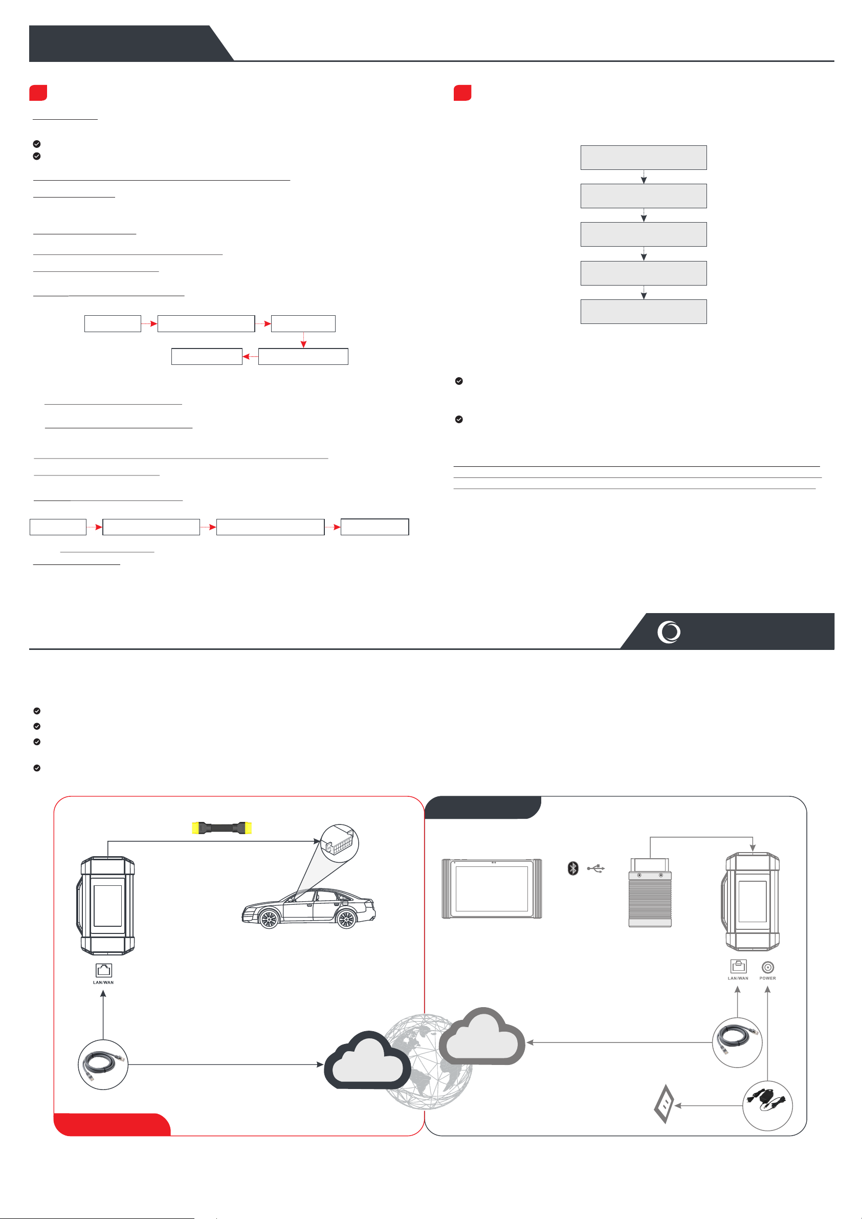
SmartLink Diag.
The SmartLink system is powerful remote diagnostics solution developed by LAUNCH. The system consists of SmartLink C dongle (for technicians seeking a trusted second opinion and
additional expertise on various vehicle issues), SmartLink Service Platform (for SmartLink C posting assistance request and SmartLink B accepting order) and SmartLink B dongle (for
service provider or master technician). Follow the steps below to perform a SmartLink session.
Post request -- Bind the SmartLink C and post a remote diagnostics request in the SmartLink module (*Only after the SmartLink C dongle is successfully bound can the request be posted).
Connection & setup -- Connect the vehicle’s DLC and crossover cable, and then set the SmartLink C as “Remote Diagnostics” mode.
Wait for partner’s assistance -- After the remote master technician accepts the order, he will provide professional technical service to you using the SmartLink B dongle (plus the
compatible diagnostic tool).
Start Diagnostics -- Turn on the ignition key and start the diagnosis. After the diagnostic session is completed, unplug the crossover cable, terminate the operation and rate the service.
Below illustrates how the SmartLink system works.
OBD II Extension Cable
Launch-specific/
Third-party Diagnostic Tool Launch-specific/
Third-party VCI
/
Vehicle's DLC
Crossover Cable
AC Outlet
Power Adaptor
(The communication
method varies with
VCI and diagnostic
tool )
Assistance Demander
Internet
Internet
SmartLink B dongle
(Master Technician)
SmartLink C dongle
(Technician)
Service Provider
* During the remote diagnosis, please do not disconnect the vehicle and the network (the network broadband of 100Mb and above is recommended). In addition, a SmartLink C dongle can only receive one
remote diagnosis operation at a time.
* When doing SmartLink diagnosis, the network delay will be displayed on the screen of the dongle. There are three states of network delay: green, yellow and red, which indicate that the network is normal, not
stable and the delay is serious respectively. It is recommended that the diagnosis operation be performed when the network delay is green. Otherwise, the communication with the vehicle may fail or the
incorrect system detection may occur.
1.
11-14 or 18-30
Preparation
Before diagnosing, please make sure the following conditions are met:
The ignition is turned on.
The vehicle battery voltage range is Volts Volts.
Preparation & Connection
Tap Local Diagnose
Select vehicle software
Select software version
Select vehicle system
Select diagnostic function
Crossover Cable


