LAUNCH TLT830WA INSTALLATION MANUAL
Notice
:
All the dimensions take the external boundary of
the floor plate as the datum.
Ensure that the overall errors shall be controlled
within 6mm(0.24″).
The line layout is very important. If not correct,
problems will happen during the final assembly
and operation.
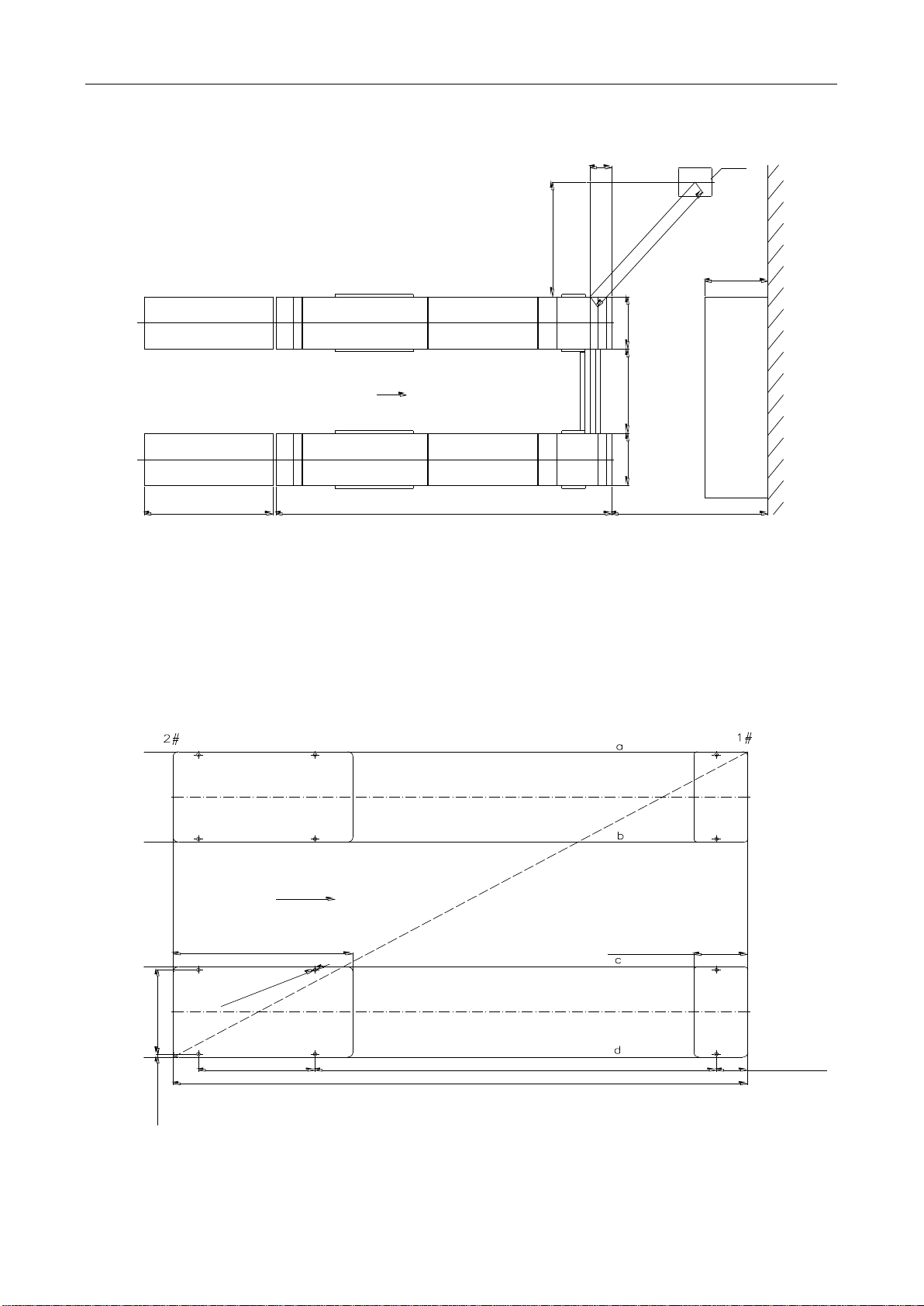
5.3 Installation on Ditch
The layout for ditch installation is similar as for ground
installation, but it is more difficult. The dimension of the ditch
channel can be seen in Fig. 8.
Notice
:
The thickness of the concrete slab is not less than
200mm. The basic intensity of the concrete slab
should reach above 3000PSI
(
2.1kgf/mm2
)
.
Lifting jack should be used to place the master
and slave units in to the ditches.
Fig.8
5.4Control Desk Installation
Select the installation site for the control desk
according to the layout.( Fig. 6)
Install the cover plate for the hoses and cables if the lift
is installed on the ground.
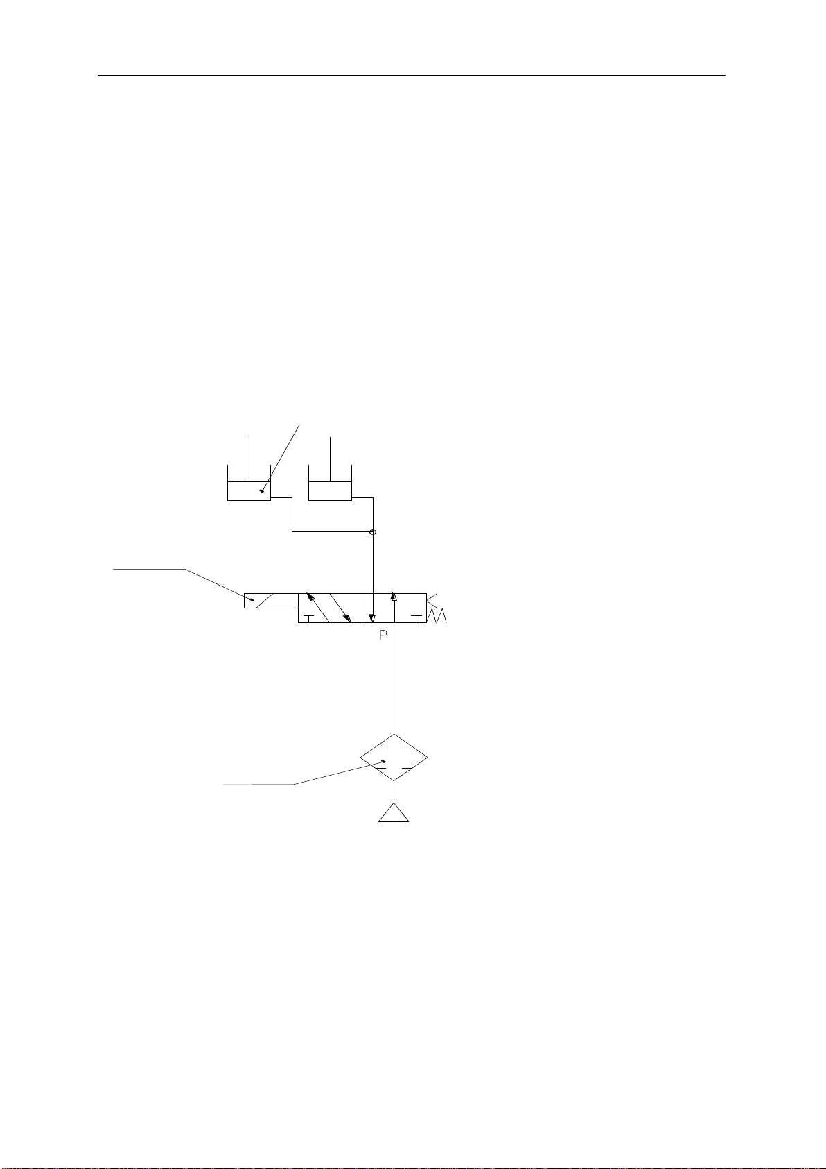
Fill the hydraulic oil to the oil tank with a proper quantity.
Do it carefully to prevent the dust or other pollution get
to the oil.
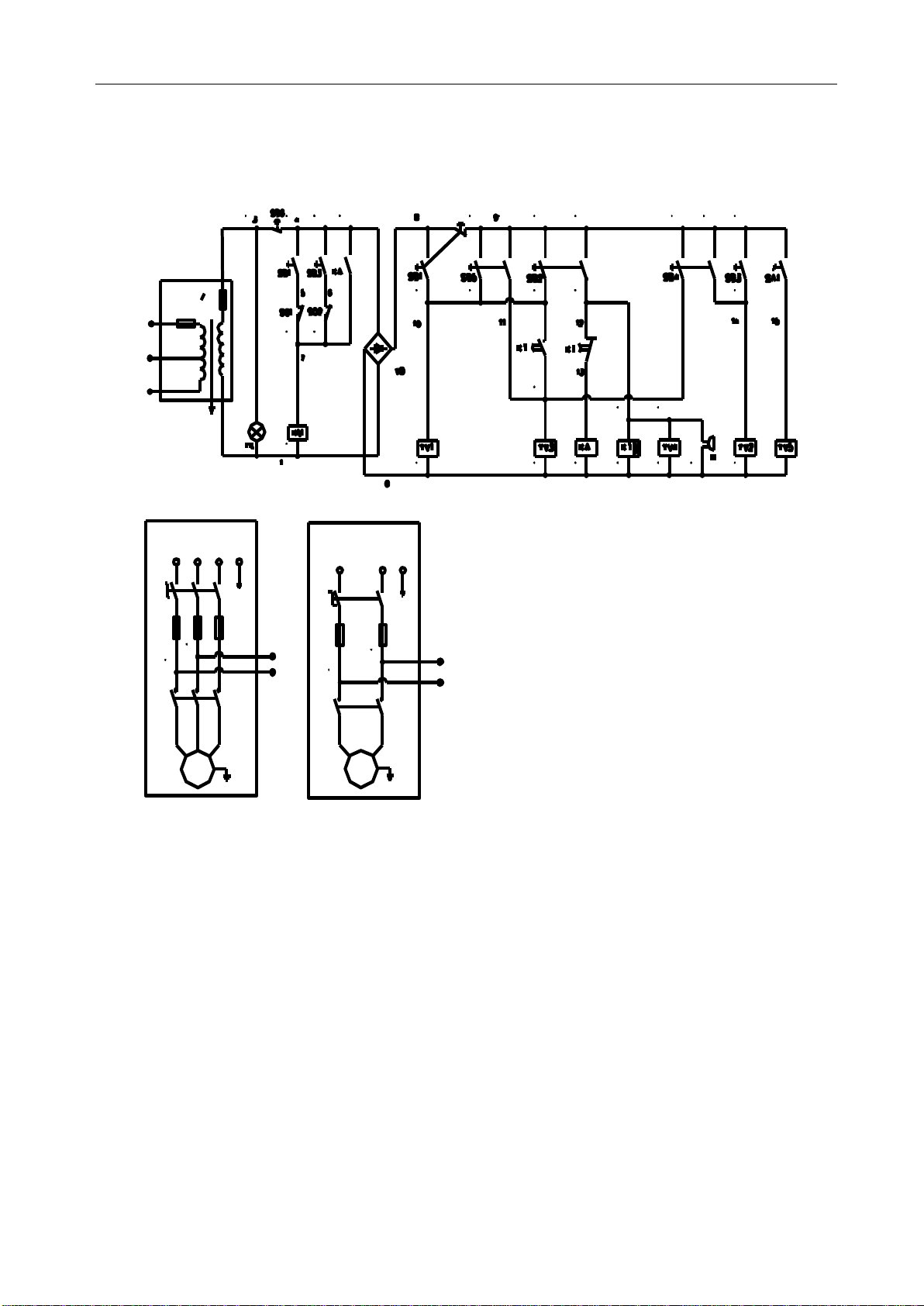
5.5 Power connection
Open the door at the back of control desk. Connect the
limit switch 1 cables on terminal 5, 7 and limit switch 2
on terminal 6, 7. Then connect power input cable to
terminal L1, L2, L3, PE (see Fig.9). The power indicator
on the operation panel should light on when the power
is on.
Fill hydraulic oil N32 or N46 into the oil tank (using oil
gauge to check the level). Pay special attention to
avoid dust and contaminants into the oil.
Note: High Voltage inside the control desk! Wiring
should be performed carefull
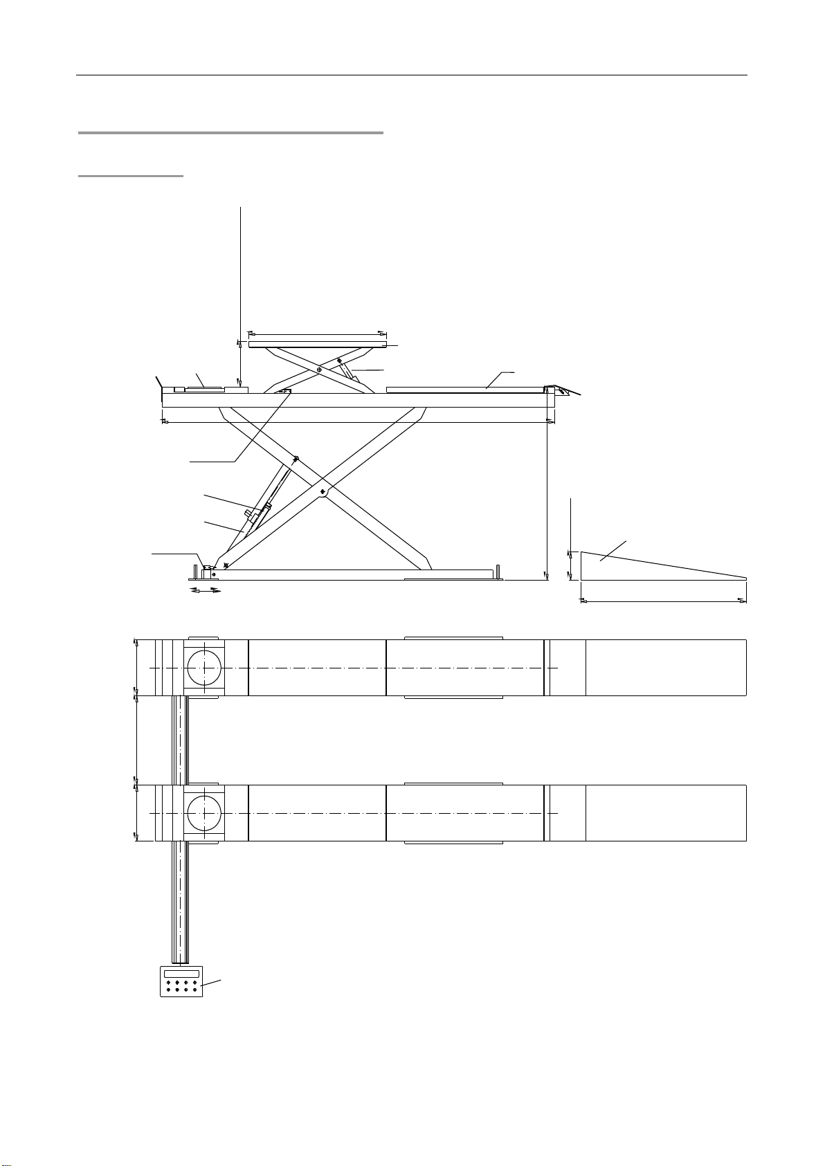
Slave Unit
Drive-On
Master Unit
min 2000mm(78.7″)
Floor
max 1800mm(70.9″)
min 1200mm(47.2″)
630mm(24.8″)800mm(31.5″)
800mm(31.5″)
Control Desk
630mm(24.8″)
Wheel Alignment
Pre-buried Pipe 100mm(3.9″)
4080mm(160.6″)
320mm(12.6″)
340mm(13.4″)
150mm(5.9″)
100mm(3.9″)