manuals.online logo
Brands
  1. Home
  2. •
  3. Brands
  4. •
  5. Lawler
  6. •
  7. Control Unit
  8. •
  9. Lawler 570 User manual

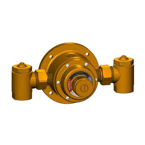
Lawler 570 User manual

ASSE 1070 Approved
ASSE 1069 Approved
R
IMPORTANT
A
B
C
Adjusting Dial
Cold Inlet
Hot Inlet
Tempered Outlet
DIMENSIONS
1 2/ "
A B C
5 7 143 5. "( . ) 4 8 121. "( ) 3 7 95. "( )
3/4" 4 8 121. "( ) 3 7 95. "( )
60
50
40
30
20
10
0
0 5 10 15 20
Flow Rate, Gal/Min
Flow Curve
Dirgram 2 Flow Characteristics-
Dirgram 1 Valve Dimensions-
5 7 143 5. "( . )
Failure to comply with all aspects ofthese instructions may resultin
unsafe performance.
All installations must comply with relevant state and local authority
requirements.
Flush the system thoroughly before fitting the valve:
It is CRITICAL that all debris is flushedfromthe pipework prior to
installing the valve.Not flushing the system properly is the most
commoncause of system difficulties.
Commission the valve:
Every valve is factory-set to a nominal temperature of 105°F. Every
must be adjusted on-site to ensure correctdelivery of the
desired mixed water temperature ,as installation conditions can vary
from site to site.
Check:
• Measure and note all site parameters (pressure , temperature, etc.)
and check against the specifications of the chosen valve. If the site
conditions are outside those specified for the valve then they must
be rectified prior to installing the valve.
• Valve MUST NOT be subjected to heat during installation as this
may damage the valve internals.
• Valve MUST NOT be fitted on steam-supplied systems, but to
water systems only.
• Valve MUST NOT be used on low pressure or instantaneous
heating systems.
• Valve MUST NOT be frozen. If the valve is installed in a situation
where freezing is a possibility, then suitable insulation must be
fitted to prevent damage to the valve.
• DO NOT use excess thread sealant (in liquid, tape or other form)
as this may cause the valve to fail.
Leave a copy of these instructions with the client for future reference.
Recommend to the client that the valve be checked annually to ensure
its continued function.
California Proposition 65 Warning
Warning: product contains chemicals known to the State of California
to cause cancer and birth defects or other reproductive harm.
(Installer: California law requires that this warning be given to
the consumer)
VALVE SPECIFICATIONS
Outlet temperature range: 95~115°F(35~46°)
Temperature, hot supply: 180°F max(82°)
Temperature, cold supply: 40~80°F(4~27°)
Temperature stability(nominal): ±5°F(±2.8°)- See Note 1.
Temperature differential: 1/2”- ±10°F(±5.5°)-See Note 2.
(between hot supply and outlet temperature) 3/4”- ±10°F(±5.5° )-See Note 2.
Hydrostatic pressure: 125psi max(1000kPa)
Permitted supply pressure variation: ±20%-See Note 3.
Flow rate @ 45psi pressure loss: 1/2”- 9gpm (66L/min)
3/4”- 11gpm
Flow rate,minimum: 0.5gpm(2L/min)
Flow rate,maximum: 1/2”- 10gpm @ 60psi pressure lost
3/4”- 12gpm @ 60psi pressure lost
Notes:
1. As testedin accordance with ASSE 1070.
2. This is the minimum difference required between the valve outlet
temperature and the hot supply temperature to ensure shut-off of outlet
flow in the event of cold supply failure, inaccordance with ASSE1070.
3.Maximum permittedvariation in either supply pressure inorder to
control the outlet temperature to with ±5°F .Excessive changes insupply
pressure may cause changes in outlet temperature, that exceed ±5°F.
Installation
Manual
MODEL 570
Thermostatic Mixing
Valve
CSA B 125.3 Approved
5330 East 25th Street
Indianapolis, Indiana 46218
Phone (317) 261-1212
Fax (317) 261-1208
www.temperedwater.com
MIXED
COLD
Showerinstallation
MIXED
COLDHOTHOT
Diagram 3 TypicalInstallations-
Diagram 4 ValveAdjustment-
TroubleshootingGuide
FAULT/SYMPTOM CAUSESOLUTION
1. Thedesiredmixed
watertemperature
cannotbeobtained or
valve is difficulttoset.
2. Mixtemperature
unstableorchanging
overtime.
3. Eitherfullhotorfull
coldwaterflowing
fromoutletfixture.
4. No flowfromthe
valveoutlet.
5. Fl ow ratereduced or
fluctuating.
6. Mixedwater
temperaturedoes
notchangewhen
temperatureadjuster
is altered.
7. Valve is noisy.
•Inlettemperaturesare
notwithinspecific
limits.
•Hotandcoldsupplies
arereversed.
•Fluctuatingsupply
pressures.
• Valve is incorrectlyset.
•Hotandcoldsupplies
arereversed .
•Hotorcoldwater
supplyfailure.
•Filterisblocked.
•Fluctuatingsupply
pressures.
•Filterisblocked.
•Hotandcoldsupplies
arereversed.
•Excessivewater
velocity.
• Valvesizedincorrectly.
•Ensureinlet
temperaturesare
withinthespecified
limitsforthevalve.
•Refitthevalvewith
Hot/Coldsupplies
fittedtothecorrect
connections.
•Installpressure
regulatingvalves on
bothhotandcold
supplies.
•Adjustmixtemperature
as required.
•Refitthevalvewith
Hot/Coldsuppliesfitted
to thecorrect
connections.
•Restoreinletsupplies
andcheckmix
temperature .
•Cleanfilter .
•Installpressure
regulatingvalves.
•Cleanfilter.
•Refitthevalvewith
Hot/Coldsuppliesfitted
to thecorrectconnections.
•Reducewatervelocity
(bestachieved by fitting a
pressureregulatingvalve).
•Checkvalvespecifications
andensuretheappropriate
valveisusedforreguired
flow.
Notes:
Fitting the Valve
• The mixed water outlet from the valve should be used to supply
outlets used primarily for personal hygiene purposes.
• It is recommended that the valve is installed as close as possible
to the point of use; however , it may be fitted anywhere on the hot
water supply pipe.
TEMPERATURE ADJUSTMENT
• Prior to setting the valve it is necessary for the hot water source to
be switched on and delivering hot water at the designated tempera-
ture .
• Test the mixed water temperature at the nearest outlet being
supplied by the valve. This should be opened to allow a flow rate of
1 to 1.5 gpm (4 to 6 Llmin).
• A thermometer must be used at the nearest outlet to the valve to
ensure the correct mixed water temperature is achieved.
• Allow the water to run for at least one minute to ensure the mixed
water temperature has settled.
• To adjust the mixed outlet temperature of the valve, remove the
cap to gain access to the adjusting spindle. The spindle should be
rotated-clockwise to reduce the temperature, counter-clockwise to
increase the temperature- until the desired set point is reached.
(Refer to diagram 4).
• Once the set temperature is achieved, the cap should be snapped
onto the valve to cover the spindle.
CHECKING / SERVICING THE VALVE
• We recommend that the valve is checked at least once per year to
ensure its continued function. For installations with poor or
unknown water quality, or other adverse supply conditions , it may
be necessary to check the valve at more frequent intervals.
• The temperature should be checked at the same outlet as was
used for commissioning in the first instance. If the temperature is
more than 3°F from the commissioning temperature, refer to fault
finding guide on the next page.
• There may be some variation in the temperature of the water from
the thermostatic mixing valve due to seasonal temperature
variations in the cold water supply.
• If the water supply is of poor quality, a filter or strainer should
be fitted to the system.
Installer, please provide the following information and leave these
instructions with the client.
Installed By:
Date:
Pressure At the Valve: PSI
Mix Temperature: F
Multiple Sensor Faucet Installation

Other Lawler Control Unit manuals

Lawler 802 Instruction Manual

Lawler

Lawler 802 Instruction Manual

Lawler NEPTUNE EMX 075 Instruction Manual

Lawler

Lawler NEPTUNE EMX 075 Instruction Manual

Lawler 61 Series Instruction Manual

Lawler

Lawler 61 Series Instruction Manual

Lawler 911E Instruction Manual

Lawler

Lawler 911E Instruction Manual

Lawler 911 E/F Series User manual

Lawler

Lawler 911 E/F Series User manual

Lawler 3000 Instruction Manual

Lawler

Lawler 3000 Instruction Manual

Lawler 410 Instruction Manual

Lawler

Lawler 410 Instruction Manual

Lawler 67 Series Instruction Manual

Lawler

Lawler 67 Series Instruction Manual

Lawler 4000 Series Instruction Manual

Lawler

Lawler 4000 Series Instruction Manual

Lawler 911 Instruction Manual

Lawler

Lawler 911 Instruction Manual

Lawler 310 Instruction Manual

Lawler

Lawler 310 Instruction Manual

Lawler 911E Instruction Manual

Lawler

Lawler 911E Instruction Manual

Lawler 803 Instruction Manual

Lawler

Lawler 803 Instruction Manual

Lawler 61 Series Instruction Manual

Lawler

Lawler 61 Series Instruction Manual

Popular Control Unit manuals by other brands

Texas Instruments DRV591 user guide

Texas Instruments

Texas Instruments DRV591 user guide

Valcom V-2000A Technical specifications

Valcom

Valcom V-2000A Technical specifications

bolid S2000-KPB instruction manual

bolid

bolid S2000-KPB instruction manual

ZIEHL-ABEGG UNIcon CPG AVC Series operating instructions

ZIEHL-ABEGG

ZIEHL-ABEGG UNIcon CPG AVC Series operating instructions

Boreal WIFI2-B Installation, operating and servicing instruction

Boreal

Boreal WIFI2-B Installation, operating and servicing instruction

YUGE LCC Series Hardware manual

YUGE

YUGE LCC Series Hardware manual

Doyson S 100 FM BT user manual

Doyson

Doyson S 100 FM BT user manual

Flowserve CPT 44 Installation, operation and maintenance instructions

Flowserve

Flowserve CPT 44 Installation, operation and maintenance instructions

Gira System 3000 user manual

Gira

Gira System 3000 user manual

Cinterion BGS3 Hardware interface description

Cinterion

Cinterion BGS3 Hardware interface description

Honeywell GSMVLP5 Installation and setup guide

Honeywell

Honeywell GSMVLP5 Installation and setup guide

American Standard R111 installation instructions

American Standard

American Standard R111 installation instructions

Daikin Myzone 3 Installation and configuration manual

Daikin

Daikin Myzone 3 Installation and configuration manual

Eaton ePDU G3HD quick start

Eaton

Eaton ePDU G3HD quick start

Locomarine 5 Series installation manual

Locomarine

Locomarine 5 Series installation manual

Niko HD-610P user manual

Niko

Niko HD-610P user manual

Beckhoff EK9500 Documentation

Beckhoff

Beckhoff EK9500 Documentation

heat-timer DiGi-SPAN Elite Series Installation and operation instructions

heat-timer

heat-timer DiGi-SPAN Elite Series Installation and operation instructions

manuals.online logo
manuals.online logoBrands
  • About & Mission
  • Contact us
  • Privacy Policy
  • Terms and Conditions

Copyright 2025 Manuals.Online. All Rights Reserved.