Lawler 4000 Series Instruction Manual

temperedwater.com
5330 East 25th St.
Indianapolis, IN 46218
Phone (317) 261-1212
Fax (317) 261-1208
INSTALLATION &
MAINTENANCE MANUAL
Design and specifications subject to change without notice.
Please refer to temperedwater.com to ensure most
current data sheet and other design solutions.
temperedwater.com/patents
M 4000 E
ASSE 1070 Approved
ASSE Lead Free Certied
Certied to CSA B125.3
NOTICE! No mixing valve will work satisfactorily if improperly installed. We suggest, therefore, that you read
these instructions carefully before installing and follow directions as outlined. Handle the mixing valve with care.
CAUTION: When maintaining and adjusting the
mixing valve, all xtures should be isolated from
use. Lawler Manufacturing Co., Inc. recommends
that you work safely at all times and in a manner
consistent with the OSHA Lock/Tagout standard,
29 CFR 1910.147 and other applicable standards.
This installation & maintenance manual covers all
congurations of the Model 4000.
Series 4000
Exposed Thermostatic
Mixing Valve
DIMENSIONS
Valve Number A B C
1/2” 1/2” 1/2” 8”
3/4” 3/4” 3/4” 9-1/2”
Dimensions are for reference purposes only. For rough-in dimensions
please refer to Lawler’s Revit/BIM models found at temperedwater.com.
82306_4205_SC6_DRW_NODIMS.pdf
A
B
C
CAPACITIES – GPM SERIES 4000
Pressure Drop PSI 5 10 20 30 45
Valve Size Capacity – GPM
1/2” 2-1/2 3-1/2 5-1/2 8 10
3/4” 5 8 10-1/2 15 20

Checking Mixing Valve
1. Check swing of handle. Move handle to maximum HOT
position counterclockwise. Short end should be pointed
to HOT. If not, pull handle off and re-set.
2. CHECKING COLD WATER SHUT-OFF. Shut off
hot supply keeping cold supply open. Now move
mixing valve handle 1/4 turn counterclockwise. A
full volume of cold water should pass through valve.
Now move mixing valve handle as far as it will go
counterclockwise. The volume of cold water should be
reduced to a very small ow.
Failure of this to occur would indicate:
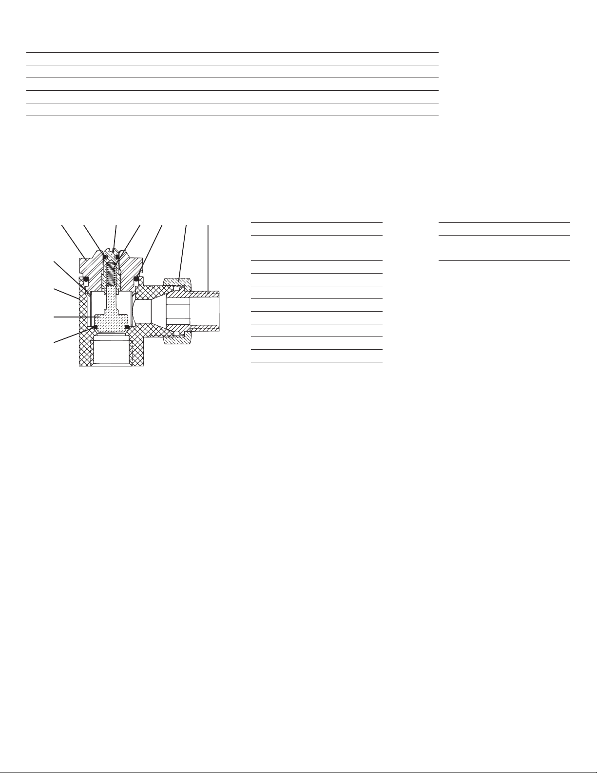
a. Piston #12 is stuck in one position. Unit has to be
cleaned.
b. Valve spring #15 has lost its strength and must be
replaced.
c. Cold water is in excess of 80°F.
3. CHECKING HOT WATER SHUT-OFF. Open both the
hot and cold supplies to mixing valve. Place handle at
hottest position (turned all the way counterclockwise).
Water should ow through valve at 115°F. If not,
adjust valve as explained under “TEMPERATURE
ADJUSTMENT.”
Now shut off the cold water supply to the mixing valve.
A properly operating mixer will shut off the hot water
almost instantly with hot water temperature supplying
the mixing valve at least 15 degrees higher than
maximum setting.
Failure to do so would indicate:
a. Dirt between the hot seat in liner and piston
prevents it from closing. Unit has to be cleaned.
b. The piston could be stuck so that it cannot move
because of scale or some other deposit in water.
Unit has to be cleaned.
c. The thermostat has lost its power and has to be
replaced with a new one.
d. On 3/4” valve only if hot pressure is over 50.p.s.i.,
valve may have a slight drip.
4. If a mixing valve will not shut off completely when
handle is turned all the way clockwise check:
a. Cold seat #9, may be worn or dirty - clean or
replace.
b. Seat of liner #16 could be eroded or cut - replace
piston & liner.
If the handle is hard to turn, remove spindle #4 and polish
with steel wool and lubricate with water insoluble grease or
Vaseline. Check O-Ring for imbedded foreign matter.
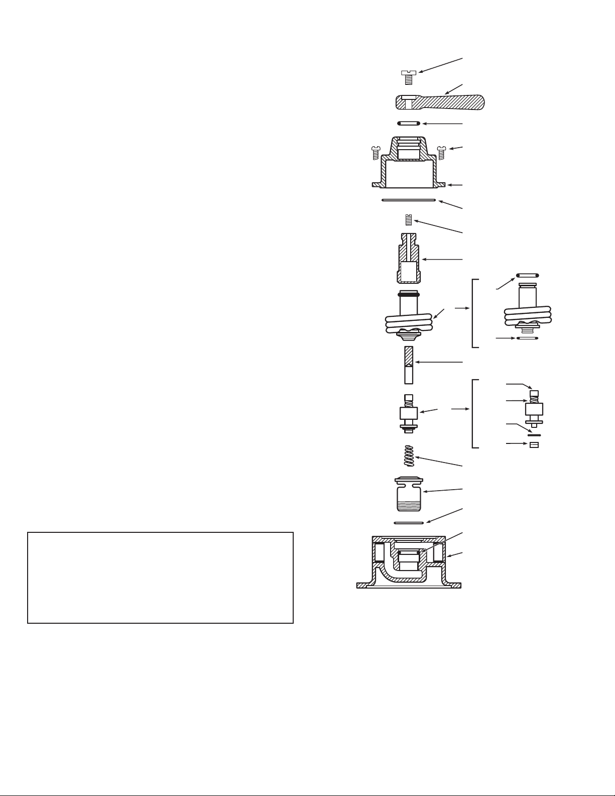
Inspection and Cleaning Valve
Shut off hot and cold water supply to mixing valve. Set
mixing valve handle on maximum hot position. Remove
body screws #22. Turn mixing valve handle toward cold
position until it forces cover off valve body. The thermostat
can now be examined.
Mixing valve
Valve is carefully assembled and tested at the factory
and set to deliver water at any temperature between full
cold and 115°F. Failure of the cold water supply will cause
the hot water seat to close. The label on the valve cover
is marked “HOT - COLD,” so that the handle can be set
accordingly.
When unit is not being used turn the handle toward COLD
position fully to shut off all ow.
Stop and Check Valves
At each inlet of the mixing valve is a screwdriver operated
union angle stop and check valve with built-in removable
sediment strainer. Both the cold and hot water angle stop
and check valves must be open at all times for proper
functioning of the valve.
The stop and check valves serve three purposes:
1. Their built-in removable strainers prevent dirt from
entering mixing valve.
2. They prevent the hot or cold water from by-passing
through the mixing valve.
3. They provide convenient means to shut the supplies to
the mixer for cleaning or repairs.
Stop and checks are required whenever downstream shut
off devices are used.
Temperature Adjustment
The temperature of the hot water supplying the mixing
valve should be at least 15 degrees higher than maximum
required valve setting. Valves are normally set at factory
for 115°F maximum outlet temperature with 140°F inlet. If
readjustment is required, proceed as follows:
1. Remove handle screw.
2. With narrow blade screwdriver, turn adjusting screw
#3 clockwise to reduce maximum outlet temperature
and counterclockwise to increase maximum outlet
temperature. This must be done with valve handle in the
hot position, turned counter-clockwise. Screw should
not be turned more than 1/2 turn at a time without
testing water temperature.
3. When temperature is correct, replace handle screw.
Adjusting screw #3 may not be turned counter-clockwise
more than 1-1/2 turns.
CAUTION: It is not recommended to set maximum
outlet temperature above the applicable plumbing code.
Piping Instructions
Before installing the mixer, blow out all pipe lines to be sure
that no dirt, such as pipe chips, wicking or lead, can enter
the mixing valve. Valve inlets are marked hot and cold.
Piping must go to proper inlets.
Maintenance
The Lawler thermostatic mixer should be checked
periodically for proper operation and cleaning. See
“INSPECTION AND CLEANING VALVE.” To test mixing
valve for proper setting and operation—proceed as follows:

Thermostatic Shower Valve Cut-away
Series 4000 cut away
1
2
5
22
6
21
3
4
8
20
12
15
16
17
18
19
11
10
14
13
7
9
Checking the Thermostat
If cold seat #9 on thermostat is worn or deeply indented,
remove it and replace with a new one. If there is a question
as to the thermostat being good, hold thermostat under
cold water faucet and insert an eraser capped pencil into
the center of thermostat. Make a reference mark where
pencil protrudes from the thermostat. Now place the entire
thermostat into hot water, approximately 125°F, for about
one minute. Remove thermostat from water, examine the
reference mark on pencil again. At this temperature, it
should extend out from former position about 1/8”. If it does
not, a new thermostat should be installed.
CAUTION: Extreme care should be exercised when
placing thermostat in and out of hot water.
Checking Piston and Liner
Remove piston assembly #12 from valve. Check the piston
assembly and liner #16 for cleanliness and excessive wear.
Check hot disc #10 for wear. Replace all worn parts.
Note: Liner #16 can be removed with a:
3/8” hex wrench for med & high ow 1/2” valves,
5/8” hex wrench for 3/4” valves.
Before reassembling the valve, thoroughly ush out with water.
Use only genuine factory parts for replacement of seat
washers; thickness will affect the operation of the mixing
valve.
When in Need of Information
When writing the factory or one of its representatives
in regard to a mixing valve, be sure to give the number
appearing on the name plate fastened to the dome.
Repair Kit
Valves can be completely rebuilt in a matter of minutes
without removal from the line by installing a repair kit.
WARNING: This product contains chemicals known
to the State of California to cause cancer and birth
defects or other reproductive harm.
(Installer: California law requires that this warning
be given to the consumer.)
For more information: www.oehha.org/prop65

GUARANTEE
We guarantee the Lawler Mixing Valve to be free from defects in workmanship and material, and for
a period of one year from date of purchase, will replace any parts found by us to be defective. We will
not be held responsible, however, for any labor incidental to, or for any damages caused by defective
material. Each mixing valve is thoroughly inspected and tested under actual conditions at our factory.
Item Description Contains 1/2” Part No. 3/4” Part No.
A Complete Repair Kit 8, 15, 20, 22, 2 (B, C) 79850-00 79851-00
B O-Ring & Gasket Kit 5, 7, 9, 10, 17, 18, 21 79959-00 79960-00
C Piston & Liner Assembly 12, 16, 17 72014-11 72014-15
D Cover & Spindle Assembly 3, 4, 5, 6, 21 72327-11 72392-12
F Thermostat Assembly 7, 8, 9, 21 71870-11 71036-10
Kits listed are for medium ow 1-5 GPM (1/2”) and 7-14 GPM (3/4”).
Repair Kits and Assemblies
Rebuilding Kit for Inlet Stop & Checks
NOTE:* Components are not included in repair kit.
Item Description
1 Adjustment Stem
2 O-ring
3 Spring
*4 Bonnet
*5 Body
6 Disc Holder
7 O-ring
8 Strainer
*9 Union Nut
*10 Union Tailpiece
11 Bonnet O-ring
Repair Kit for Two Stop & Checks
Valve Part No.
1/2” 79902-03
3/4” 79894-02
7
6
5
8
42 9103111
Other Lawler Control Unit manuals

Lawler
Lawler 911E Instruction Manual

Lawler
Lawler 67 Series Instruction Manual

Lawler
Lawler 61 Series Instruction Manual

Lawler
Lawler 410 Instruction Manual

Lawler
Lawler NEPTUNE EMX 075 Instruction Manual

Lawler
Lawler 3000 Instruction Manual

Lawler
Lawler 310 Instruction Manual

Lawler
Lawler 911 E/F Series User manual

Lawler
Lawler 803 Instruction Manual

Lawler
Lawler 911 Instruction Manual
Popular Control Unit manuals by other brands

Delta
Delta TECK COMMERCIAL R2570-MIXLFBOX Installation notes

Paradox
Paradox MG-RCV3 Reference and installation manual

SPX FLOW
SPX FLOW WR60 Series instruction manual

Blackbe;rry
Blackbe;rry RADAR-L installation guide

Black Box
Black Box T568B manual

Astral Pool
Astral Pool CONTROL BASIC PLUS installation manual