LEAB Clayton Power G3 Combi 1012-50 User manual

LEAB Automotive GmbH
Thorshammer 6
DE-24866 Busdorf
User Manual
Version: 2.0
Issue date: 12.02.2019
G3 Combi from
1012-50, 1024-30, 1312-80,
1512-80, 1524-40, 2012-100, 2324-50
Lightweight and compact sine wave inverter and battery charger
User Manual

User Manual About this Manual
Page 1 of 22
Table of Contents
1About this Manual ..................................................................................1
2General Safety.........................................................................................2
3Technical Specifications ..........................................................................3
4Package contents ....................................................................................6
5About the Combi.....................................................................................7
6Component Drawing and Description.....................................................9
7Mounting ..............................................................................................10
8Installation ............................................................................................10
9Normal Operation ................................................................................. 12
10 Functions............................................................................................... 12
11 Control Displays and Error Descriptions ...............................................17
12 Maintenance.........................................................................................18
13 Mount Neutrik Plug............................................................................... 18
14 Disposal.................................................................................................19
15 EU Declaration of Conformity ...............................................................19
1About this Manual
Read this manual carefully and keep it in a safe place. This manual is
intended for electrically trained persons and professionals in the
automotive electrical field.
Throughout the manual, you will be alerted to warnings and safety notices
about potential hazards associated with handling the device. The colours
and signal words indicate the severity of the hazard:

User Manual General Safety
Page 2 of 22
Signal word
Meaning
DANGER
Warns of imminent danger resulting in death or
serious injury.
WARNING
Warns of a potentially dangerous situation that can
result in death or serious injury.
CAUTION
Warns of a potentially dangerous situation that can
result in moderate or minor injuries.
NOTICE
Warns of a potentially dangerous situation that can
result in material and environmental damage.
In this manual you will find the following symbols:
Shows you useful tips and information about the device.
Indicates a mandatory requirement for the following
instruction.
Shows the result of an instruction.
2General Safety
This manual supports the safe handling of the device. Use the device solely
in accordance with its intended use:
The G3 Combi with a lightweight and compact design has switching power
supply technology and is suitable for mobile and stationary use. The
inverter integrated in the G3 Combi converts DC voltage into sinusoidal AC
voltage, which also supplies sensitive consumers. The G3 Combi is also
suitable for charging lead-acid batteries (wet, gel, AGM) and lithium
batteries.
The integrated mains priority circuit supplies consumers (AC) with an
external 230-V supply via the 230-V mains. In the event of a failure of the
230-V mains power supply (AC), the backup power supply enables an
almost uninterruptible switchover (from approx. 25 ms) to inverter
operation.

User Manual Technical Specifications
Page 3 of 22
Any modifications to the device or its components are prohibited and do
not conform to its intended use.
Observe the following safety instructions:
Device defect due to incorrect installation: Install the device in a dry
and cool location.
Danger from damaged, frozen or deformed batteries:
Before operation, make sure that the battery is undamaged and the
electrolyte is not frozen.
Only charge batteries in well-ventilated rooms and away from ignition
sources.
When handling open batteries, wear acid-proof clothing.
3Technical Specifications
12-V Devices
Model
1012-50
1312-80
1512-80
2012-100
Output power
Continuous power
1,000 W
1,300 W
1,500 W
2,000 W
Overload (1 s)
2,000 W
3,000 W
3,000 W
4,000 W
Overload (10 s)
1,500 W
1,800 W
2,000 W
2,800 W
Overload (15 min)
1,200 W
1,500 W
1,700 W
2,200 W
Degree of efficiency
>90%
Internal consumption
Normal idling speed
10 W
15 W
Idling with search mode
< 2 W
Standby mode
< 5 mA
Operating temperature
Max. operating
temperature
+50°C
Min. operating
temperature
-20°C
Switch-off temperature
+80°C
Output voltage (AC)
Nominal voltage
230 V
Voltage tolerance
-10% ... +5%
Frequency
50 Hz
Voltage waveform
Sine
Max. distortion (THD)
3%

User Manual Technical Specifications
Page 4 of 22
Model
1012-50
1312-80
1512-80
2012-100
Input voltage (DC)
Nominal voltage of the
battery
12 V
Max. input voltage
15 V
Switch-off voltage
(Response time 3 s)
10.5 V
Switch-off voltage
(Response time < 10 s)
9 V
Switch-on voltage (restart)
12.75 V
Mechanical specification
Protection class
IP21
Dimensions, housing
(LxWxH)
299 x 198.2 x
116 mm
376 x 198.2 x 116 mm
Dimensions, housing with
connections (LxWxH)
334 x 198.2 x
116 mm
412 x 198.2 x 116 mm
Weight
6 kg
7.5 kg
Battery
Battery type
Lead-acid (wet, gel AGM) and lithium
Charging characteristic
IU1U2
Temperature sensor (NTC)
optional
Charging current
(adjustable)
0-50 A
0-80 A
0-80 A
0-100 A
Current reduction at 50°C
0%
Current reduction at 60°C
15%
Current reduction at 80°C
50%
Charging voltage (default setting)
Main charging
14.4 V
Trickle charging
13.5 V
Supply voltage (AC)
Max. input voltage
265 V
Minimum voltage for main
charging
185 V
Minimum voltage for
trickle charging
110 V
Max. current peaks
100 A
Frequency
45 Hz … 65 Hz
Cos φ
0.9
Integrated input fuse
10 A

User Manual Technical Specifications
Page 5 of 22
24-V Devices
Model
1024-30
1524-40
2324-50
Output power
Continuous power
1,000 W
1,500 W
2,300 W
Overload (1 s)
2,000 W
3,000 W
3,000 W
Overload (10 s)
1,500 W
1,800 W
3,000 W
Overload (15 min)
1,200 W
1,700 W
2,500 W
Degree of efficiency
>90%
Internal consumption
Normal idling speed
10 W
15 W
Idling with search mode
< 2 W
Standby mode
< 5 mA
Operating temperature
Max. operating
temperature
+50°C
Min. operating
temperature
-20°C
Switch-off temperature
+80°C
Output voltage (AC)
Nominal voltage
230 V
Voltage tolerance
-10% ... +5%
Frequency
50 Hz
Voltage waveform
Sine
Max. distortion (THD)
3%
Input voltage (DC)
Nominal voltage of the
battery
24 V
Max. input voltage
30 V
Switch-off voltage
(Response time 3 s)
21 V
Switch-off voltage
(Response time < 10 s)
18 V
Switch-on voltage (restart)
25.5 V
Mechanical specification
Protection class
IP21
Dimensions, housing
(LxWxH)
299 x 198.2 x 116 mm
376 x 198.2 x
116 mm
Dimensions, housing with
connections (LxWxH)
334 x 198.2 x 116 mm
412 x 198.2 x
116 mm
Weight
6 kg
7.5 kg

User Manual Package Contents
Page 6 of 22
Model
1024-30
1524-40
2324-50
Battery
Battery type
Lead-acid (wet, gel AGM) and lithium
Charging characteristic
IU1U2
Temperature sensor (NTC)
optional
Max charging current
(adjustable)
0-30 A
0-40 A
0-50 A
Current reduction at 50°C
0%
Current reduction at 60°C
15%
Current reduction at 80°C
50%
Charging voltage (default setting)
Main charging
28.8 V
Trickle charging
27 V
Supply voltage (AC)
Max. input voltage
265 V
Minimum voltage for main
charging
185 V
Minimum voltage for
trickle charging
110 V
Max. current peaks
100 A
Frequency
45 Hz … 65 Hz
Cos φ
0.9
Integrated input fuse
10 A
4Package Contents
Package contents
G3 Combi
x1
AC output plug, Neutrik NAC3FCB model –grey
x1
Phoenix plug, MSTB 2.5 / 3-ST-5.08 –green
x1
AC input plug, Neutrik NAC3FCA model –blue
x1
Manual
x1
User Manual About the Combi
Page 7 of 22
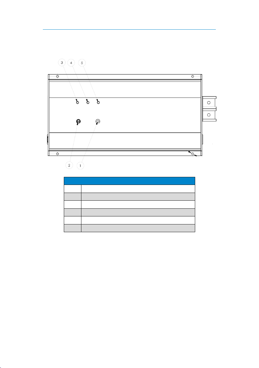
5About the Combi
Details
No.
Description
1
On/off button
2
Potentiometer charging current limitation in %
3
Charger LED –green
4
Inverter LED –blue
5
Battery LED –red

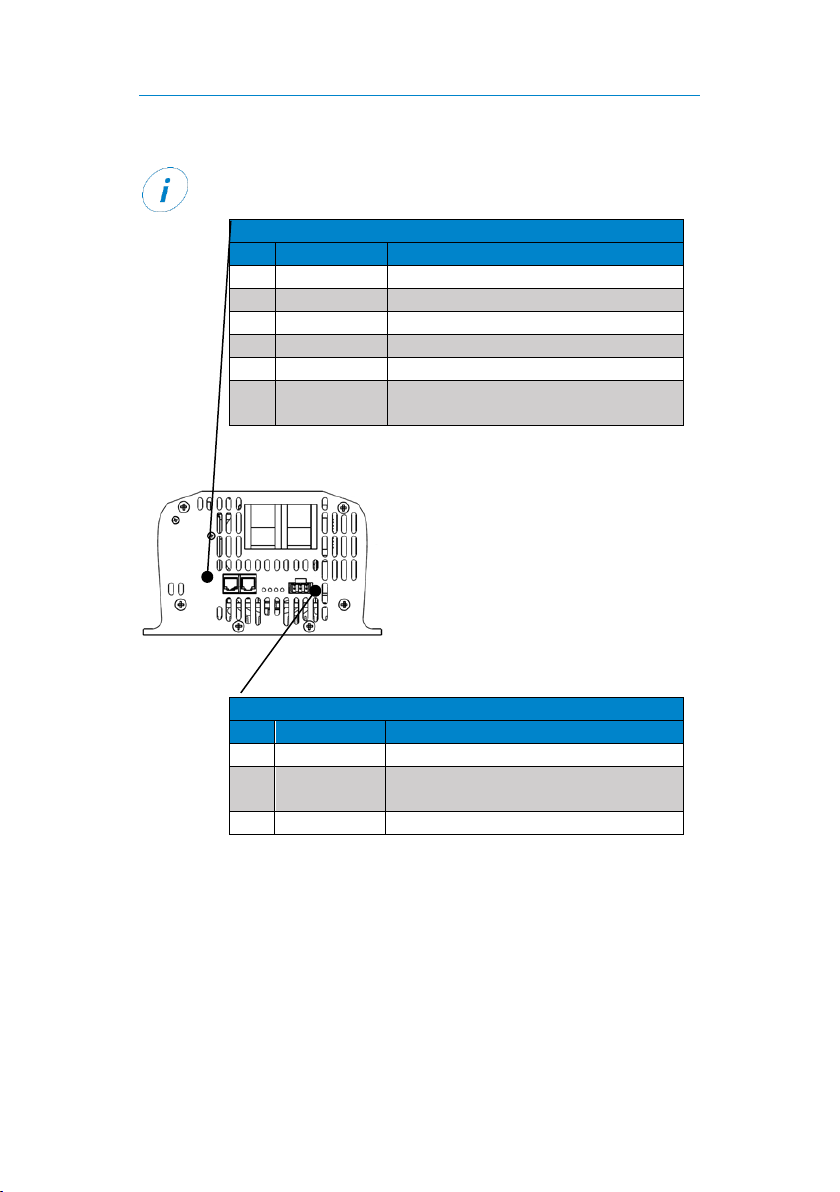
User Manual About the Combi
Page 8 of 22
Control displays
Pos.
Colour
Function
A
Green
Illuminates when
data connection
is “high”
B
Yellow
Illuminates when
data connection
is “low”
C
Orange
Illuminates when
remote switch
“on”
D
Not assigned
Details
No.
Description
6
AC input, Neutrik model –blue
7
Connection, positive terminal of the battery
8
Connection, negative terminal of the battery
9
Data connection, model RJ12 (6P6C)
10
Data connection, model RJ12 (6P6C)
11
Data connection, Phoenix model –green
12
Fuse, AC input
13
AC inverter output, Neutrik model –grey
Control displays
between the data
slots
User Manual Component Drawing and Description
Page 9 of 22
6Component Drawing and Description
The pins for single wire communication are connected in parallel.
Plug, RJ12
Pin
Signal
Description
1
-Temp X1
Temperature sensor (-)
2
Ground
Ground, consumer (fused)
3
+Temp X1
Temperature sensor (+)
4
Sync_In/Out
Not assigned
5
Data
Single wire communication (Clayton)
6
Remote
Connection for connecting an
external on/off switch.
Plug, Phoenix Combicon
Pin
Signal
Description
1
Data
Single wire communication (Clayton)
2
Remote
Connection for connecting an
external on/off switch.
3
Not assigned
User Manual Mounting
Page 10 of 22
7Mounting
To mount the device, perform the following steps:
NOTICE
Choose a cool, dry and well-ventilated mounting site. The device must
be protected from dust and moisture.
Do not mount the device directly next to or above batteries.
Mount the device on a flat surface.
Optimum cooling is achieved with vertical mounting.
1. Fasten the device with screws to the 4 lateral holes (5 mm Ø).
The device is mounted.
8Installation
Determining the Cable Cross-section of the Input Lead (DC)
The following table shows the required cable cross-sections in relation to
the respective cable length. Select the cross-sections so that the voltage
drop to the G3 Combi is no more than 250 mV.
To avoid voltage dips, select a higher cable cross-section for
consumers with high starting currents (e.g. motors, compressors).
Cable
Cross-
section
Device model
mm2
1012-
50
1312-
80
1512-
80
2012-
100
1024-
30
1524-
40
2324-
50
15
-
-
-
-
1.5 m
-
-
25
1.5 m
-
-
-
2.5 m
1.5 m
-
35
2 m
1.5 m
1.5 m
-
3 m
2.5 m
1.5 m
50
3 m
2 m
2 m
1.5 m
-
3 m
2 m
70
-
3 m
2.5 m
2 m
-
-
3 m

User Manual Installation
Page 11 of 22
Connecting the Battery (DC Cable)
To connect the battery, perform the following steps:
1. Connect one DC cable to the negative terminal of the device.
2. Connect one DC cable to the positive terminal of the device.
3. Connect the negative terminal of the device to the negative terminal
of the battery.
4. Secure the positive cable as close as
possible to the vehicle battery with a
suitable fuse (see table).
5. Connect the positive terminal of the
device with the positive terminal of the
battery.
The battery is connected.
Connecting the Remote Switch
To connect an external remote switch, perform the following steps:
1. Connect an external on/off switch to the positive terminal of the
battery (DC voltage min. 10 V, max. 30 V).
Notice: Secure the on/off switch with max. 1 A (with 0.75 mm2).
2. Connect the on/off switch to the remote pin of the device.
The remote switch is connected.
Connecting Consumers
To connect consumers, perform the following steps:
1. Insert the plug of the consumer into the Neutrik input (grey) of the
device.
A Neutrik plug is included. You will find information on how to
install the Neutrik plug on p. 18.
2. Be sure that sufficient personal and line safety devices are available
according to your application.
The consumer is connected.
Model
Fuse
1012
125 A, slow-blow
1024
80 A, slow-blow
1312
175 A, slow-blow
1512
175 A, slow-blow
1524
100 A, slow-blow
2012
250 A, slow-blow
2324
150 A, slow-blow

User Manual Normal Operation
Page 12 of 22
9Normal Operation
Switching On
The device is mounted and installed.
To switch on the device, perform the following steps:
1. Press the on/off button for 2 s.
Red and blue LEDs illuminate.
Red LED goes out.
Blue LED illuminates and indicates the start process.
Blue LED lights up continuously, AC voltage is activated.
The device is switched on.
Switching Off
To switch off the device, perform the following steps:
1. Press the on/off button for 0.5 s.
Blue LED goes out.
Device switches off.
The device is switched off.
10 Functions
Standby Mode
If the AC voltage is not required continuously, a standby mode can be
activated. In standby mode, the internal consumption is less than 2 W. In
standby mode, the device generates a short pulse every 2 seconds.
If the actual consumption is more than 10 W, the device
switches on.
If the consumer is switched off, the device switches to standby
mode after 1 minute.
The standby mode cannot be activated or deactivated via an
external remote switch.
The standby mode is not suitable for lithium batteries.

User Manual Functions
Page 13 of 22
Activating the Standby Mode
To activate the standby mode, perform the following steps:
The device is switched off.
1. Press the on/off button until the blue and red LEDs illuminate.
The standby mode is activated.
Deactivating the Standby Mode
To deactivate the standby mode, perform the following steps:
The device is switched off.
1. Press the on/off button until the blue and red LEDs flash.
The standby mode is deactivated.
Battery Charging
The battery is charged automatically as soon as a supply voltage
(185 V –265 V) is applied to the AC input.
The battery is also charged when the device is switched off.
The charging takes place with reduced charging current when
the supply voltage (AC) is between 110 V and 185 V.
Mains Priority Circuit
The mains priority circuit is activated automatically when a supply voltage
(AC) is applied to the AC input.
If a supply voltage is applied to the AC input, the consumers are supplied
with power by the 230-V mains and batteries are charged by the charger.

User Manual Functions
Page 14 of 22
Backup Power Supply
The backup power supply is only provided when the inverter
function is switched on.
As soon as the supply voltage is interrupted, the integrated inverter
supplies the consumers with power from the batteries with almost no delay
(from approx. 25 ms).
If a supply voltage is once again applied to the AC input again, the G3 Combi
automatically switches back and supplies the consumers. In addition, the
battery is recharged.
Charging Process
Battery charging takes place with a 3-stage IU1U2 characteristic curve for
gentle and optimum charging of the batteries.
The characteristic curves can be adapted by LEAB to the batteries
to be charged.
Charging with constant current (I-phase, green LED flashes fast)
In order to store as much energy as possible in the battery as quickly as
possible, it is charged at the maximum charging current, depending on the
battery charge status. In order not to damage the battery, heavily
discharged batteries are first charged with reduced current. After a certain
main charging voltage (depending on battery type) has been reached, the
G3 Combi switches to the next charging phase.
I U1 U2

User Manual Functions
Page 15 of 22
Charging with constant voltage (U1phase, green LED flashes slowly)
In this phase the battery is fully charged. The voltage is kept constant at a
value of 14.4 V (standard value). As the charge of the battery increases, the
current decreases continuously and approaches a lower limit which
depends on the type and size of the battery. As soon as the value falls
below this or a safety time is exceeded, the charger switches to phase 3.
Charge retention with reduced voltage (U2phase, green LED illuminates)
In this phase, the charging voltage is reduced to 13.5 V (standard value) in
order to maintain the battery charge and counteract self-discharge. In this
phase, additionally connected consumers are supplied via the charger
without placing strain on the battery.
Load Reduction
The charger integrated in the G3 Combi automatically limits the charging
current when the total load (charging and output power) exceeds the rated
power.
Charging Current Limit
The charging current limit is pre-set at the factory according to
customer wishes.
The maximum charging current can be set using the potentiometer on the
top of the device. The table shows the recommended charging current in
relation to the battery capacity.
Charging
current
Capacity
15 A
75 Ah …150 Ah
20 A
100 Ah …200 Ah
25 A
100 Ah …250 Ah
30 A
150 Ah …300 Ah
40 A
200 Ah …400 Ah
50 A
250 Ah …500 Ah
60 A
300 Ah …600 Ah
80 A
400 Ah …800 Ah
120 A
600 Ah …1200 Ah

User Manual Functions
Page 16 of 22
Temperature Compensation (NTC Sensor)
If an external temperature sensor (NTC) is connected, the charging voltage
adapts to the battery voltage in relation to the ambient temperature.
The figure shows the adjustment of the charging voltage in relation to the
operating temperature (in degrees Celsius). The upper line is the voltage
line for the main charging process. The lower line is the voltage line for the
trickle charge.
blue = final voltage red = trickle charge

User Manual Control Displays and Error Descriptions
Page 17 of 22
11 Control Displays and Error Descriptions
Blue LED
Description
Steady light
Inverter in operation
…..…..…..…..…..
Start mode –Load adjustment
....….......................
Output overloaded
....……...........
Operating temperature too high
(automatic cooling and restart)
....……..
Short-circuit at the inverter output
....
Short-circuit in the power supply
....
Overload in the power supply during the
start process
Green LED
Description
Steady light
Charging status: U2phase
Slow flashing
Charging status: U1phase
Fast flashing
Charging status: I phase
…..…..…..…..…..
Supply voltage (AC) too low (< 185 V)
No sine-wave voltage present
....….......................
Supply voltage (AC) too high (> 265 V)
Red LED
Description
Off
Battery voltage OK
Steady light
Battery voltage low
To prevent battery draining, the device
switches off as soon as the battery
voltage drops below 10.3 V.
..............
Battery voltage too high
Red and green LED
Description
....
Failure of the external temperature
sensor (NTC)
If no external NTC is connected, the
signal appears for 20 s after switching
on the supply voltage (AC).

User Manual Maintenance
Page 18 of 22
All LEDs
Description
Flickering
Remote and mains switch on the device
at the same time
....….......................
NTC error (internal temperature sensor)
....……...........
Overvoltage in the internal high-voltage
DC connection
....……..
Defect in half of the bridge circuit
....
Defect in the entire bridge circuit
12 Maintenance
Maintain the device at regular intervals.
Ensure that the cables on the battery and the G3 Combi are
secure.
To ensure the air supply, clean the ventilation grille of the device.
13 Mount Neutrik Plug
Use the following plug to connect the consumers:
AC output plug, Neutrik NAC3FCB model –grey
AC input plug, Neutrik NAC3FCA model –blue
Connections Cable preparation
Sleeve Insert Clamp sleeve Screw connection

User Manual Disposal
Page 19 of 22
Coding, type A (blue) Coding, type B (grey)
14 Disposal
Dispose of the device in accordance with the Waste Electrical and
Electronic Equipment Regulations (WEEE).
The device must not be disposed of with household waste. Take
it to a recycling point or send it to your point of sale.
15 EU Declaration of Conformity
The G3 Combi
in models 1012-50, 1024-30, 1312-80,
1512-80, 1524-40, 2012-100, 2324-50
complies with the requirements of the following directives:
2014/30/EC: EMC
2014/35/EC: NRL
2011/65/EC: RoHS
The current and complete document is available on request from
This manual suits for next models
6
Table of contents
Other LEAB Batteries Charger manuals

LEAB
LEAB TS 24/12-06 User manual

LEAB
LEAB Champ User manual

LEAB
LEAB CHAMP 12 V User manual

LEAB
LEAB CHAMP 12 V User manual

LEAB
LEAB Champ 1207 User manual

LEAB
LEAB CHAMP PRO 24 V User manual

LEAB
LEAB TS 12 User manual

LEAB
LEAB CPC 1260 User manual

LEAB
LEAB CDR 12/24 V User manual

LEAB
LEAB RBC 1280 User manual


Popular Batteries Charger manuals by other brands


DEFA
DEFA MultiCharger 1x20A user guide

Learning by Questions
Learning by Questions Tablet Charging Cabinet v1 PDU Operating and safety instructions

EDWANZ group
EDWANZ group Deutronic DBL-MPC4 Series manual

Siemens
Siemens 5TT3 201 Series operating instructions

Hilti
Hilti C7 Original operating inctructions

Luxor
Luxor LLTP32-B Assembly instructions


